Table of Contents
Advertisement
Quick Links
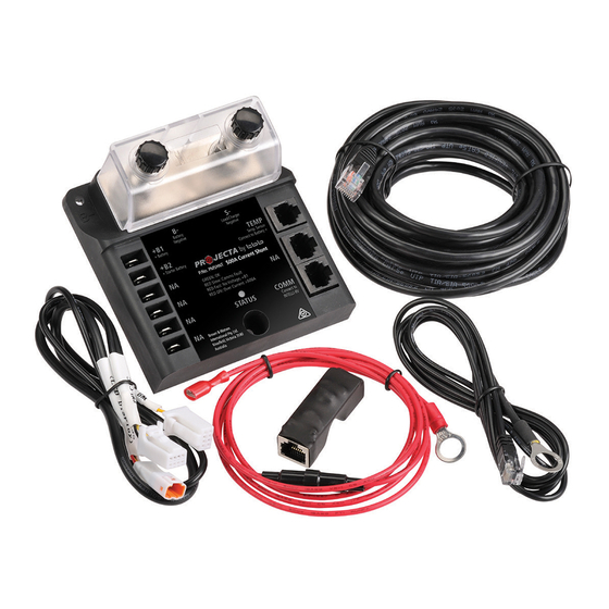
INTELLI-RV
500AMP SHUNT MODULE
P/No. PMSHUNT
INSTALLATION GUIDE
Please read this document very carefully to avoid battery monitor
malfunction or fire hazards.
The active shunt must be located in a dry environment.
MOUNTING THE MODULE
Do not use mounting screws with countersunk heads.
WARNING:
l The shunt must always be installed into the negative line.
l The battery negative terminal may only contain one cable, which is the one going
to the shunt. If there are other cables connected to this terminal as well, this may
WARNING
produce incorrect display readings.
l Always connect the battery negative terminal to the 'B-' stud of the shunt.
Connecting this terminal to the 'S-' stud will produce incorrect display readings.
Always disconnect the battery negative cable first before installation.
Always connect the battery negative cable last when the installation has been
completed.
More information https://www.caravansplus.com.au
Advertisement
Table of Contents

Related Manuals for Projecta INTELLI-RV


Summary of Contents for Projecta INTELLI-RV
- Page 1 INTELLI-RV 500AMP SHUNT MODULE P/No. PMSHUNT INSTALLATION GUIDE Please read this document very carefully to avoid battery monitor malfunction or fire hazards. The active shunt must be located in a dry environment. MOUNTING THE MODULE Do not use mounting screws with countersunk heads.
- Page 2 Keep these cables (to load) as short as possible! Battery negative (system ground) 12V, 24V or 48V + B2 Service battery + B1 Starter battery Note: Starter battery connection optional as the INTELLI-RV already measures the starter battery voltage. More information https://www.caravansplus.com.au...
- Page 3 SETUP VIA THE APP 3 Confirm to complete 1 Enter setting menu, 2 Select ”Active ”to Select “Shunt” option enable BM500 shunt setup. SET UP VIA LCD l Press the ‘Light’ button until the setting code is showing on the date time area which means the monitor is ready for configuration.
- Page 4 PM300 + PMSHUNT WIRING DIAGRAM 0.5m PMWS200 or PMLCD-BT PMWS400 PMLCDC Cells+DOD BM COM (4 Pin Wire): 4.5m PMLCDC-SY PMSWEX-2: 2m extension or PMSWEX-4: 4m extension PMSHEX-5: 5m extension PMTS: 4.5m PMTS: 0.5m PMTEX-2: 2m extension or PMTEX-4: 4m extension PV IN Vmp: 17-50V, 30A PV IN +...
- Page 5 PMWEX-4: 4m extension PMWS200: 4m PMWEX-4: 4m extension 0.5m PM335 PMWS200 or PMWS400 PMWS200: 4m PMWS200: 4m PMWS200: 4m PMBS: 0.5m PMBEX-2: 2m extension or PMWEX-4: 4m PMBEX-4: 4m extension PMWEX-4: 4m extension extension PMBS: 2.5m 0.5m PMWS200 or Service Battery + 0.5m PMWS400 PMWS200 or...
- Page 6 PM400 + PMSHUNT WIRING DIAGRAM 0.5m PMWS200 or PMLCD-BT PMWS400 PMLCDC Cells+DOD BM COM (4 Pin Wire): 4.5m PMLCDC-SY PMSWEX-2: 2m extension or PMSWEX-4: 4m extension PMSHEX-5: 5m extension PM4SW10C: 4.5m PM4Y: 0.5m PMTEX-2: 2m extension or PMTEX-4: 4m extension PMTEX-2: PM4SW10 PMTS: 4.5m...
- Page 7 PMWEX-4: 4m extension PMWS200: 4m PMWEX-4: 4m extension 0.5m PM435 PMWS200 or PMWS400 PMWS200: 4m PMWS200: 4m PMWS200: 4m PMBS: 0.5m PMBEX-2: 2m extension or PMWEX-4: 4m PMBEX-4: 4m extension PMWEX-4: 4m extension extension PMBS: 2.5m 0.5m PMWS200 or Service Battery + 0.5m PMWS400 PMWS200 or...
- Page 8 WARRANTY STATEMENT Applicable only to product sold in Australia Brown & Watson International Pty Ltd of 1500 Ferntree Gully Road, Knoxfield, Vic.,telephone (03) 9730 6000, fax (03) 9730 6050, warrants that all products described in its current catalogue (save and except for all bulbs and lenses whether made of glass or some other substance) will under normal use and service be free of failures in material and workmanship for a period of two (2) years (unless this period has been extended as indicated elsewhere) from the date of the original purchase by the consumer as marked on the invoice.
Need help?
Do you have a question about the INTELLI-RV and is the answer not in the manual?
Questions and answers