
Related Manuals for Projecta INTELLI-RV PM435-BT

Summarization of Contents
IMPORTANT SAFETY INFORMATION
Warnings and Precautions
List of safety precautions and warnings for using the product safely.
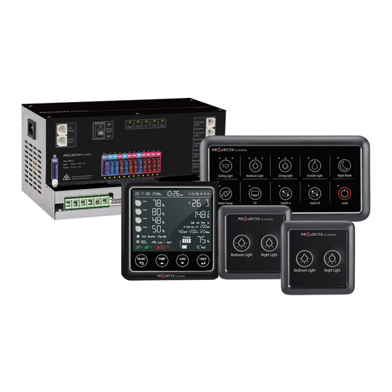
INTRODUCTION AND SYSTEM OVERVIEW
Product Features
Lists the key features and capabilities of the PM400 power management system.
Monitor Functionality
Describes the monitor as a digital control center for the on-board power system.
Switch Panel Functions
Details the preconfigured functions of the 10-position and 2-position switch panels.
Water Tank Monitoring
Describes the available water tank probes for monitoring fluid levels.
KEY FEATURES AND FUNCTIONS
Input Sources
Explains how the PM435 accepts inputs from AC mains, Solar, and Starter Battery sources.
Service Battery Charging
Details the multi-stage charging algorithm for service batteries, including stages.
Vehicle Battery Charging
Describes the PM435's float charge capability for maintaining the starter battery.
MPPT Solar Charging
Details the built-in Maximum Power Point Tracking (MPPT) solar charger for the service battery.
Voltage Charging Relay (VCR)
Explains the function of the built-in voltage charging relay (VSR) for charging the service battery.
Output Categorization
Describes how the 14 PM435 outputs are categorized into different groups for specific controls.
Battery Protection Features
Explains Battery Low Voltage Protection (LVD) and precise battery measurement capabilities.
Scene Mode Operation
Explains the preconfigured scene modes like "Night mode" and "Night Light" for various controls.
STRUCTURE AND INSTALLATION
PM435 Unit Layout
Details the front panel connections, ports, and components of the PM435 unit.
Monitor Installation Guide
Provides dimensions and instructions for installing the monitor unit.
Switch Panel Installation
Shows dimensions and installation procedures for the PM4SW10 and PM4SW2 switch panels.
Water Tank Probe Installation
Details dimensions and installation procedures for the PMWS400 and PMWS200 water tank probes.
WIRING AND CONNECTIONS
Package Contents
Lists the components included in the PM400 package for installation.
System Wiring Schematic
Provides a system schematic illustrating how components are interconnected.
Wiring Preparation
Offers recommendations for minimum wiring cable sizes and preparation steps.
Terminal Connections
Details the PM435 unit's terminal types and recommended cable gauges for secure connections.
DISPLAY AND USER INTERFACE
PM435 Unit Indicators
Explains the LED indicators on the PM435 power management system unit.
Switch Panel Interfaces
Details the buttons and functions of the 10-position and 2-position switch panels.
Monitor Display Information
Shows an overview of the monitor and lists the types of information displayed.
Monitor Symbol Guide
Explains the meaning of the various symbols shown on the monitor screen.
Monitor Switch Functions
Details the specific functions associated with the monitor's control switches.
OPERATION AND CONFIGURATION
PM435 Configuration
Explains how to configure the PM435 unit, including battery settings and charging parameters.
Battery Settings
Details setting battery capacity and type using dip switches on the PM435.
Battery Switch Selection
Explains how to select between local and remote battery switch operation modes.
Monitor Configuration Menu
Guides on accessing and configuring system settings via the monitor interface.
Switch Panel Usage
Explains the operation of switch panels, including dimming and scene mode functionalities.
TROUBLESHOOTING
PM435 LED Status Indicators
Explains the meaning of different LED indicator states on the PM435 unit.
Monitor Error Codes
Lists and explains various error codes that may appear on the monitor display.
Need help?
Do you have a question about the INTELLI-RV PM435-BT and is the answer not in the manual?
Questions and answers