TECOM Challenger10 Installation And Quick Programming Manual
Hide thumbs
Also See for Challenger10:
- Administrator's manual (72 pages) ,
- Installation and programming manual (46 pages)

Related Manuals for TECOM Challenger10


Summary of Contents for TECOM Challenger10
- Page 1 Challenger10 Installation and Quick Programming Manual P/N MAINST-TS1016 • REV 01 • ISS 18FEB13...
- Page 2 Copyright © 2013 UTC Fire & Security. All rights reserved. Trademarks and The Challenger name and logo are trademarks of patents UTC Fire & Security. Other trade names used in this document may be trademarks or registered trademarks of the manufacturers or vendors of the respective products.
-
Page 3: Table Of Contents
Clearing the memory 24 Basic programming sequence 25 Working with multi-area systems 26 Default installer PIN 26 Enabling communications 27 Programming users 31 Firmware upgrade process 32 Requirements 32 Getting ready 32 Upgrade process 32 Challenger10 Installation and Quick Programming Manual... -
Page 4: Important Information
While every precaution has been taken during the preparation of this manual to ensure the accuracy of its contents, Interlogix assumes no responsibility for errors or omissions. Challenger10 Installation and Quick Programming Manual... -
Page 5: Regulatory Requirements For New Zealand
• The associated equipment shall be set to ensure that calls are answered between 3 and 30 seconds of receipt of ringing. Refer to the Challenger10 Programming Manual for details about programming these parameters. Challenger10 Installation and Quick Programming Manual... -
Page 6: Preface
Preface This is the Challenger10 Installation and Quick Programming Manual. It is part of the following suite of manuals for the Challenger10 intrusion detection and access control panel. • The Challenger10 Installation and Quick Programming Manual is for installation technicians to install a Challenger panel. -
Page 7: Product Overview
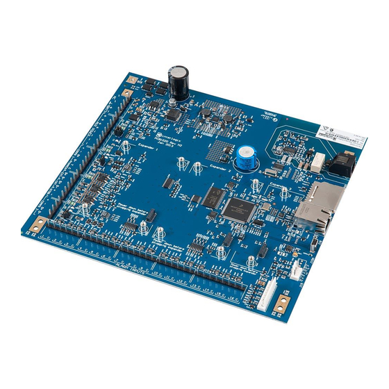
(DGP). These devices extend the system’s intrusion detection and access control functions. Refer to the Challenger10 Programming Manual for details. Product contents Table 1 below lists the items that are shipped with TS1016 Challenger10. Table 1: Challenger panel shipping list Quantity Item Metal enclosure (with four spring standoffs fitted) Challenger panel board 604 to RJ12 lead line, 1.5 m... -
Page 8: Before You Begin
Earthing of one cabinet containing several devices. All devices designed for the system have earth connections via metal studs to the metal housing. Take care that these metal studs have a good connection to bare metal (no paint). Challenger10 Installation and Quick Programming Manual... - Page 9 TS0893, to isolate the system LAN between buildings to protect the system against differences in earth potential. See Figure 3 on page 7. Guidelines for retrofitting a Challenger V8 system When replacing a Challenger V8 panel with a Challenger10 panel in an existing installation: •...
- Page 10 Do not connect the power supply + to the LAN +. • Connect the external power supply’s ‘-’ terminal to the device ‘-’ terminal. • Connect the LAN cable black wire ‘-’ to the device ‘-’ terminal. Challenger10 Installation and Quick Programming Manual...
- Page 11 TERM link on RAS without earth terminal TERM link off RAS without earth terminal TERM link off External power supply (if needed) Data gathering panel LAN Earth (last device on LAN) Power Earth TERM link on Challenger10 Installation and Quick Programming Manual...
-
Page 12: System Configurations
A star LAN that has multiple branches in excess of 100 m may need to use LAN isolation devices such as TS0893 LAN Isolation Interface modules to isolate the LAN segments that do not have LAN termination set to ON. Challenger10 Installation and Quick Programming Manual... - Page 13 Figure 3: RS-485 LAN cabling between two buildings Building A Building B Challenger Panel T=On T=Off T=On T=Off TS0893 TS0893 T=On T=On T=On T=On T=On (termination link fitted) T=Off (termination link not fitted) Challenger10 Installation and Quick Programming Manual...
- Page 14 Challenger LAN data to be carried over an IP network and to be converted back to RS-485 communications for connection to LAN devices. Refer to the Interlogix Web site at www.interlogix.com.au for details and images of LAN devices. Challenger10 Installation and Quick Programming Manual...
-
Page 15: Installing The Control Panel
Only a qualified electrician or other suitably trained and qualified person should attempt to wire this system to mains power (if applicable) or to the public telephone network. Challenger10 Installation and Quick Programming Manual... -
Page 16: Installation Procedures
To mount the tamper switch: The two-way tamper switch detects removal of the cover from the enclosure, and removal of the enclosure from the wall. 1. Insert the tamper switch into its metal bracket. Challenger10 Installation and Quick Programming Manual... -
Page 17: Connections
Challenger panel board’s LAN earth terminal. Connect the power terminals to a 16 Volt AC plug pack. Maximum current drawn by the panel with no peripheral devices connected is approximately 200 mA. Challenger10 Installation and Quick Programming Manual... - Page 18 Link 1 is used when resetting the master installer code (“Restoring the default installer PIN” on page 27) and for defaulting the panel (“Clearing the memory via the Challenger panel PCB” on page 24). Challenger10 Installation and Quick Programming Manual...
- Page 19 When installing plug packs, do not power the unit until you have terminated all necessary wires and checked that you do not have a short circuit. Fused plug packs cannot be replaced under warranty as the fuse operation can only be caused by a direct short circuit. Challenger10 Installation and Quick Programming Manual...
- Page 20 In a completely-connected (but powered down) system, you can check for correct LAN termination by measuring the resistance across the Challenger panel’s D+ and D- terminals: • 0 Ω indicates a short circuit in the cabling Challenger10 Installation and Quick Programming Manual...
- Page 21 Use Install menu option 23 Poll Errors to check for poll errors on the LANs. If the rate of poll errors seems excessive, check the LAN cabling and termination. Zone inputs Zone inputs are also known as alarm inputs. A Challenger10 system can receive alarm signals from: •...
- Page 22 When the system is used in 2-state configuration, inputs can only report sealed and unsealed states. This prohibits the use of input types that need to detect short or open states. See the Challenger10 Programming Manual for details. Special zone input types Zone inputs programmed as area control type inputs can also be used to turn areas on and off (as opposed to entering a PIN on a keypad).
- Page 23 10 kΩ (normal state of key switch) indicates sealed • 5 kΩ or 20 kΩ indicates unsealed (isolated, no alarm generated) • Open circuit generates a tamper alarm • Short circuit generates an alarm Challenger10 Installation and Quick Programming Manual...
-
Page 24: Led Indications
PCB” on page 24) or firmware update (“Firmware upgrade process” on page 32). • Tx0 (item 19) flashes to indicate data being sent from the Challenger to a device connected to J15 (serial port). On solid when J15 is ready (inactive). Challenger10 Installation and Quick Programming Manual... - Page 25 • Rx2 (item 26) flashes to indicate remote units on LAN 2 are replying to polling. • Link active (item 17) flashes when Ethernet is active. • 100BT (item 15) on when Ethernet speed is 100 Mbps. Challenger10 Installation and Quick Programming Manual...
-
Page 26: Initial Programming
An LCD RAS configured as RAS 1 must be connected to LAN 1. Disarming the system A new (or defaulted) Challenger10 panel is armed, and the RAS LED for area 1 illuminates. Previous Challenger versions armed all areas. The system must be completely disarmed before you can access the Install menu on a system keypad (LCD RAS). - Page 27 This manual describes the Challenger programming that you may need for basic system setup. Refer also to: • Challenger10 Programming Manual for details of Challenger system programming via the Install menu. Challenger10 Administrators Manual for details of Challenger programming •...
- Page 28 Tester event flag time is set to 15 seconds • Siren time is set to 8 minutes • Mains fail time is set to 0 minutes • Card to code time is set to 8 seconds Challenger10 Installation and Quick Programming Manual...
- Page 29 Display the site number and ID number of the last card read by a reader connected directly to the control panel (doors 1 to 16 on LAN 1 and doors 65 to 80 on LAN 2). Challenger10 Installation and Quick Programming Manual...
-
Page 30: Clearing The Memory
1. From the Install menu option 14 Defaults, press 99 [ENTER] to reset all custom programming. Clearing the memory via the Challenger panel PCB You may want to perform a “panel default” to reset the panel to its factory default state and erase all programming. Challenger10 Installation and Quick Programming Manual... -
Page 31: Basic Programming Sequence
Holidays must also be assigned one or more holiday types (1 to 8). Decide what each holiday type will be used for, and record the purpose in the Holidays and Holidays Types worksheets (see the Challenger10 Administrators Manual). 10. Program time zones via Install menu option 13 Time Zones. -
Page 32: Working With Multi-Area Systems
20. Program (at least) the first user. See “Programming users” on page 31. Working with multi-area systems Challenger10 can have up to 99 areas. New or defaulted Challenger panels can arm and disarm only areas 1 to 16. This functionality is accomplished via Area Group 1, which contains areas 1 to 16. -
Page 33: Enabling Communications
If reporting via the Challenger panel’s onboard modem, the Communications option “New Zealand Dialling” must be enabled. Challenger10 programming Challenger10 panels have a range of communications options, configured via Install menu 9 Communications. The first two options in the Communications menu are: •... - Page 34 (the highest priority being 1), or 0 for no priority assignment. Also, a communication path can be designated as a backup to another communication path. A Challenger10 panel has default values programmed for the following communications paths: • Path 1. CID Dialler—For reporting to a remote monitoring company via a telephone connection.
- Page 35 Example 2: Programming an event-driven IP connection to a Titan computer You may use a Cat 5 cable to connect the Challenger panel to a Titan computer (either directly or via LAN). Challenger10 Installation and Quick Programming Manual...
- Page 36 UDP/IP as the communications mode. Save the record. 16. Select Open/System from the File menu, select Active System, and then save the record. The connection indicator at the bottom of the Titan window displays green to indicate a successful connection. Challenger10 Installation and Quick Programming Manual...
-
Page 37: Programming Users
Unless you will be programming (adding) the system’s users yourself, you will need to program at least one administrator who will be able to program additional users. See Challenger10 Administrators Manual for details. The default values for User 50, the master code, are: •... -
Page 38: Firmware Upgrade Process
Firmware upgrade process This section describes how to upgrade Challenger10 panel firmware. It is provided here as an interim guide only, and is subject to change. Note: During the upgrade process, the Challenger panel will not be able to receive or report alarm signals. We recommend that you follow the general instructions listed in the Challenger10 Programming Manual, “Recommended... - Page 39 “Install from a list or specific location” radio button, and then click Next. 8. Click to select the “Search for the best driver in these locations” radio button, and then browse to include the location of the Tecom Firmware Loader application in the search (for example, C:\Program Files\Tecom Firmware Loader\inf_driver).
Need help?
Do you have a question about the Challenger10 and is the answer not in the manual?
Questions and answers