TECOM Challenger10 TS1016 Installation And Programming Manual
Hide thumbs
Also See for Challenger10 TS1016:
- Administrator's manual (72 pages) ,
- Installation and quick programming manual (39 pages)

Related Manuals for TECOM Challenger10 TS1016


Summary of Contents for TECOM Challenger10 TS1016
- Page 1 Challenger Series ® Installation and Quick Programming Manual P/N MAINST-TS1016 • REV 07 • ISS 20AUG15...
- Page 2 Copyright © 2015 UTC Fire & Security Australia Pty Ltd. All rights reserved. Trademarks and The Challenger name and logo are trademarks of UTC Fire & patents Security Australia Pty Ltd. Other trade names used in this document may be trademarks or registered trademarks of the manufacturers or vendors of the respective products.
-
Page 3: Table Of Contents
Content Important information ..................ii Agency compliance ................ii Limitation of liability ................ii Regulatory requirements for New Zealand ......... iii Preface ........................ iv Product overview ....................1 Product contents .................. 1 ChallengerSE functionality ..............2 ChallengerLE functionality ..............3 Before you begin .................... -
Page 4: Important Information
Important information Agency compliance This product conforms to the standards set by Standards Australia on behalf of the Australian Communications and Media Authority (ACMA). Enclosure covers must remain fitted in order to maintain C-Tick compliance. Limitation of liability To the maximum extent permitted by applicable law, in no event will Interlogix (a division of UTC Fire &... -
Page 5: Regulatory Requirements For New Zealand
Regulatory requirements for New Zealand Some parameters required for compliance with Telecom’s Telepermit requirements are dependent on the equipment (PC) associated with this device. In order to operate within the limits for compliance with Telecom’s Specifications, the associated equipment shall be set to ensure that: •... -
Page 6: Preface
Preface This manual applies to the following Challenger Series control panels: • Challenger10 (model TS1016 with external 16 Volt AC plug pack or model TS1016T with internal 240 VAC mains transformer). • ChallengerSE (model TS1016SE) with external 16 Volt AC plug pack. Refer to “ChallengerSE functionality”... -
Page 7: Product Overview
Product overview Challenger is a scalable intrusion detection and access control system. Challenger panels use one, and optionally a second, RS-485 data bus (LAN) to provide continuous polling of remote arming stations (RAS) and data gathering panels (DGP). These devices extend the system’s intrusion detection and access control functions. -
Page 8: Challengerse Functionality
ChallengerSE functionality User capacity TS1016SE Challenger Standard Edition (ChallengerSE) panels support 100 users. This capacity can be expanded to 2,000 users via a TS1082 User Expansion Licence or 65,535 users via a TS1084 Memory Expansion Module. Note: If a ChallengerSE control panel needs more than 2,000 users, then a TS1084 Memory Expansion Module must be used in place of the TS1082 User Licence Module. -
Page 9: Challengerle Functionality
ChallengerLE functionality TS1016LE Challenger Lite Edition (ChallengerLE) panel capacities differ from Challenger10 panels in certain respects. Refer to the Challenger Series Programming Manual, R06 (or later) or the product data sheet for specific details. The ChallengerLE capacities of note to installers are: •... -
Page 10: Before You Begin
Before you begin This section contains items that govern the installation of many different Challenger system devices (including but not limited to the Challenger panel). When installing a Challenger panel, or any other parts of the system, you need to be aware of requirements for cabling and earthing, and plan accordingly. - Page 11 Earthing of one cabinet containing several devices. All devices designed for the system have earth connections via metal studs to the metal housing. Take care that these metal studs have a good connection to bare metal (no paint). Earthing of panels in a single building. In a single building several cabinets or devices are earthed.
- Page 12 • In each segment of LAN cabling, connect one end only of the data cable shield to a device’s LAN earth terminal. Join data cable shields where cable extends past a device that doesn’t have a LAN earth connection. • The length of the LAN cable run should not exceed 1.5 km, unless LAN isolation devices are used to extend the distance.
- Page 13 Figure 1: RS-485 LAN 1 or LAN 2 and earth system block diagram Challenger Series Installation and Quick Programming Manual...
-
Page 14: System Configurations
Figure 1 legend Item Description RS-485 LAN cable. We recommend the use of 2-pair twisted shielded data cable such as Belden 8723 for optimal performance. Join data cable shields where cable extends past a device that doesn’t have a LAN earth connection. - Page 15 Figure 2: Star LAN configuration Multi-building or long-distance LAN cabling If the RS-485 LAN extends to more than one building, each building must have its own earth system. LAN isolation devices, such as TS0893 LAN Isolation Interface modules, are used to isolate the system LAN between buildings to protect the system against differences in earth potential.
- Page 16 Item Description LAN segment 2 extends from the TS0893 in building A to the TS0893 in building B. Termination is ON at both TS0893 modules. Maximum cabling distance for segment 2 is 1500 metres. Earth point on Challenger panel connected to building earth via plug pack earth wire (green).
-
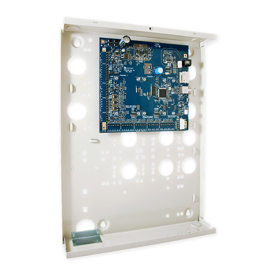
Page 17: Installing The Control Panel
Installing the control panel See Figure 4 below for overall details of a TS1016 or TS1016SE Challenger panel installed in a TS0307 Universal Enclosure. See Figure 5 on page 12 for overall details of a TS1016T Challenger panel and 240 VAC mains transformer installed in a TS0307 Universal Enclosure. See Figure 6 on page 13 for overall details of a TS1016LE Challenger panel installed in its enclosure. - Page 18 Figure 5: Challenger panel board mounted in enclosure (model TS1016T) Figure 5 legend Item Description Enclosure mounting points Board mounting points Location of tamper switch 240 VAC terminal block with fuse 240 VAC mains transformer Mains power cord Challenger Series Installation and Quick Programming Manual...
-
Page 19: Installation Guidelines
Figure 6: Challenger panel board mounted in enclosure (model TS1016LE) Figure 6 legend Item Description Enclosure mounting points Board mounting points (two screws at bottom, slots at top) Location of tamper switch Accessory board mounting bosses (on side of enclosure) Installation guidelines Challenger panels are designed, assembled and tested to meet the requirements related to safety, emission and immunity with respect to environmental electrical... -
Page 20: Installation Procedures
• Model TS1016T Challenger panel is powered from a 240 VAC mains transformer and earthed via mains power earth. • A power outlet (GPO) must be in proximity to the panel. Only qualified Electricians should provide a GPO. • The Challenger panel may have an onboard dialler or may be fitted with a plug-on dialler module (TS1016LE). -
Page 21: Board Details (Ts1016, Ts1016T, Ts1016Se)
3. Slide the board’s terminal connectors together and mount them to the board. Board details (TS1016, TS1016T, TS1016SE) See Figure 7 below for models TS1016, TS1016T, or TS1016SE. Figure 7: Model TS1016, TS1016T, or TS1016SE board details Figure 7 legend Item Description Connect one end of each LAN cable shield to the ring terminal and fasten with M3 screw... - Page 22 Item Description Connect the D+ and D– terminals to the RS-485 data cable for LAN 1. If the + and – terminals are used, consider the current draw as part of the auxiliary power output. See “Auxiliary power terminals” on page 21. Input and common terminals for panel tamper switch (supplied).
- Page 23 Item Description LED 1 flashes slowly to indicate panel operation, and flashes quickly during firmware update or panel default. Transmit and receive LEDs to indicate activity on LAN 1. Tx1 transmit LED flashes to indicate the Challenger panel is polling remote units (RASs and DGPs) on LAN 1.
-
Page 24: Board Details (Ts1016Le)
Board details (TS1016LE) See Figure 9 below for model TS1016LE. Figure 9: Model TS1016LE board details Figure 9 legend Item Description Connect one end of the LAN cable shield to the ring terminal and fasten with M3 screw to the Challenger panel board’s LAN earth terminal. Connect the + and –... - Page 25 Item Description Connect the + and – terminals to the strobe. The maximum current draw for the external 8 Ω siren and the strobe is 700 mA. The strobe output is relay 2 and is mapped to event flag 2. Zone input terminals.
- Page 26 Figure 10: Connection details for terminal block J1 Figure 11: Connection details for terminal blocks J2 to J3 Figure 12: Connection details for terminal block J4 ChallengerLE panels have onboard connectors for eight input circuits, with common terminals shared between adjacent terminals, as shown in Figure 13 below.
-
Page 27: Application Notes
Application notes 16 VAC plug pack (models TS1016, TS1016SE, or TS1016LE) Notes • Use the 16 VAC plug pack supplied with the Challenger panel. • When installing plug packs, do not power the unit until you have terminated all necessary wires and checked that you do not have a short circuit. Fused plug packs cannot be replaced under warranty as the fuse operation can only be caused by a direct short circuit. - Page 28 RS-485 LAN termination All Challenger LAN devices (including the panel) use a 470 Ω LAN termination resistor where required. LAN termination resistors are used to set the impedance of the LAN to around 220 Ω in order to minimise noise. The termination resistor may be external or onboard (devices with an onboard resistor use a link or a DIP switch to set the LAN termination to ON).
- Page 29 Install EOL resistors in zone input circuits at the end of the circuit. If an alarm device is connected, place the EOL resistors at the device’s connections. If a zone input is not used, you don’t need to connect an EOL resistor if you program the corresponding input number as type 10 (spare).
- Page 30 If connecting the Challenger panel to other configurations of zone input circuits, the placement and values of EOL resistors may differ. In any case, you must test the installation to avoid unexpected results. Figure 14: Four-state monitored zone input circuits Alternatively, the Challenger system can be configured to monitor zone inputs for two states (sealed and unsealed).
- Page 31 Figure 16: Wiring of key switches for input types 6 and 31 Input type 6 is used for momentary area control. • The normal state of the key switch is sealed • When unsealed the programmed alarm group functions are performed Input type 31 is used for toggling area control.
-
Page 32: Telephone Connection
Telephone connection See Figure 7 on page 15, item 13. Some Challenger panel models are supplied with a pre-wired 604 plug for connection to a 611 socket for PSTN in connection mode 3 for dialler reporting formats (see Figure 18 below). Figure 18: Line connections for 611 socket for dialler reporting formats J15 serial port See Figure 7 on page 15, item 20 or Figure 9 on page 18, item 15. -
Page 33: Initial Programming
Initial programming This section describes basic initial programming via a RAS. Advanced programming is typically performed via management software such as Titan, Security Commander, or Forcefield, so basic programming also includes the items required to connect with a management software computer. Refer to the documentation provided with the management software for additional details. - Page 34 This manual describes the Challenger programming that you may need for basic system setup. Refer also to: • Challenger Series Programming Manual for details of Challenger system programming via the Install menu. Challenger Series Administrators Manual for details of Challenger •...
- Page 35 Table 3: Install menu options and selected default values Install menu option Description 1. Input Database Program all physical inputs on the control panel, DGP, or plug-in expander, and inputs that are activated by macros. The default values for inputs 1 to 16 are: •...
- Page 36 Install menu option Description 7. System Options Program the system options if the default values are not suitable. The default values for system options are: • Film Low is set to 800 • Film Out is set to 1100 • Input tamper monitoring is selected •...
-
Page 37: Clearing The Memory
Install menu option Description 24. Download Download access control data for Intelligent Access Controllers (4-door or 4-lift DGPs) that may not have been downloaded automatically. Note: Intelligent Access Controllers are not applicable to ChallengerLE. 25. Display Last Card Display the site number and ID number of the last card read by a reader connected directly to the Challenger system LAN (not via an Intelligent Access Controller). -
Page 38: Basic Programming Sequence
To clear the panel’s memory via RAS: 1. From the Install menu option 14 Defaults, press 99 [ENTER] to reset all custom programming. Clearing the memory via the Challenger panel PCB You may want to perform a “panel default” to reset the panel to its factory default state and erase all programming. -
Page 39: Working With Multi-Area Systems
Holidays must also be assigned one or more holiday types (1 to 8). Decide what each holiday type will be used for, and record the purpose in the Holidays and Holidays Types worksheets (see the Challenger Series Administrators Manual). 9. Program time zones via Install menu option 13 Time Zones. 10. -
Page 40: Default Installer Pin
Default installer PIN Changing the default installer PIN The default panel programming includes PIN 4346 for user 50. The default PIN must be changed to keep unauthorised persons from modifying your programming or using the system without authorisation. Note: Unlike previous versions of Challenger panels, you can’t actually delete user 50 from the panel (however, user 50 can be deleted from management software and from 4-Door or 4-Lift Controllers). - Page 41 Notes for New Zealand application: • Refer to “Regulatory requirements for New Zealand” on page iii. • If reporting via the Challenger panel’s onboard modem, the Communications option “New Zealand Dialling” must be enabled. Challenger programming Challenger panels have a range of communications options, configured via Install menu 9 Communications.
- Page 42 The following default values are typically sufficient to establish communications with the management software computer: • Security password 0000000000 • Security attempts 255 Note: It is advisable to change the settings for the password and security attempts once the management software is communicating with the Challenger panel.
-
Page 43: Programming Users
See Challenger Series Administrators Manual for details. The default values for User 50, the master code, are: • Name TECOM Master • PIN 4346 •... -
Page 44: Firmware Upgrade Process
A powered and functioning Challenger panel. • A Windows PC with a USB 2.0 port. • Tecom Firmware Loader application. • Access to the Challenger panel’s printed circuit board (PCB). • A USB cable to connect the Windows computer to the Challenger panel’s... - Page 45 “Install from a list or specific location” radio button, and then click Next. 8. Click to select the “Search for the best driver in these locations” radio button, and then browse to include the location of the Tecom Firmware Loader application in the search (for example, C:\Program Files\Tecom Firmware Loader\inf_driver).
- Page 46 17. Use Install menu option 11 Version, option 1, to display the Challenger version number. It should display the new version number. 18. We recommend that you also default the panel’s programming. From the Install menu option 14 Defaults, press 99 [ENTER] to reset all custom programming.
Need help?
Do you have a question about the Challenger10 TS1016 and is the answer not in the manual?
Questions and answers