
Subscribe to Our Youtube Channel
Related Manuals for TECOM ChallengerPlus


Summary of Contents for TECOM ChallengerPlus
- Page 1 ChallengerPlus Installation and Quick Programming Manual P/N MAINST-TS-CHPLUS • REV 1.7 • ISS 16AUG19...
- Page 2 Copyright © 2019 UTC Fire & Security Australia Pty Ltd. All rights reserved. Trademarks and The Challenger name and logo are trademarks of UTC Fire & patents Security Australia Pty Ltd. Other trade names used in this document may be trademarks or registered trademarks of the manufacturers or vendors of the respective products.
-
Page 3: Table Of Contents
Firmware upgrade process ........Error! Bookmark not defined. Requirements ........Error! Bookmark not defined. Getting ready ........Error! Bookmark not defined. Upgrade process ........ Error! Bookmark not defined. Appendix C: Operating temperature ..............41 ChallengerPlus Installation and Quick Programming Manual... -
Page 4: Important Information
Important information Agency compliance This product conforms to the standards set by Standards Australia on behalf of the Australian Communications and Media Authority (ACMA). Enclosure covers must remain fitted in order to maintain ACMA compliance. Limitation of liability To the maximum extent permitted by applicable law, in no event will Interlogix (a division of UTC Fire &... -
Page 5: Regulatory Requirements For New Zealand
• The associated equipment shall be set to ensure that calls are answered between 3 and 30 seconds of receipt of ringing. Refer to the ChallengerPlus Programming Manual for details about programming these parameters. ChallengerPlus Installation and Quick Programming Manual... -
Page 6: Preface
Challenger system via its text-based user interface (in particular the “Install” menu”). • The ChallengerPlus Users Manual is suitable for most users of the Challenger system to perform everyday tasks. • The ChallengerPlus Administrators Manual is for users and system administrators who need to manage the Challenger system via its text-based user interface (in particular the User menu). -
Page 7: Product Overview
(RAS) and data gathering panels (DGP). These devices extend the system’s intrusion detection and access control functions. Refer to the ChallengerPlus Programming Manual for details. Product contents Table 1 below lists the items that are shipped with Challenger control panels. -
Page 8: Before You Begin
Before you begin This section contains items that govern the installation of many different Challenger system devices (including but not limited to the Challenger panel). When installing a Challenger panel, or any other parts of the system, you need to be aware of requirements for cabling and earthing, and plan accordingly. - Page 9 TS0893, to isolate the system LAN between buildings to protect the system against differences in earth potential. See Figure 3 on page 7. Guidelines for retrofitting a Challenger V8 system When replacing a Challenger V8 panel with a ChallengerPlus panel in an existing installation: •...
- Page 10 • Where used, a device’s GND or EARTH link must be removed (if fitted). Note: ChallengerPlus panels do not have a GND link. • Where 240/16 VAC plug packs are used, connect the earth conductor to the device’s power earth terminal (similar to Figure 5 on page 11, item 3).
- Page 11 Figure 1: RS-485 LAN 1 or LAN 2 and earth system block diagram ChallengerPlus Installation and Quick Programming Manual...
-
Page 12: System Configurations
Figure 1 legend Item Description RS-485 LAN cable. We recommend the use of 2-pair twisted shielded data cable such as Belden 8723 for optimal performance. Join data cable shields where cable extends past a device that doesn’t have a LAN earth connection. - Page 13 Each TS0893 module has a pair of termination links, used to terminate (if applicable) the LAN segment on each side of the module’s isolation barrier. Figure 3: RS-485 LAN cabling between two buildings ChallengerPlus Installation and Quick Programming Manual...
- Page 14 Figure 3 legend Item Description LAN segment 1 extends from the Challenger panel to one side of the TS0893 LAN Isolation Interface. Termination is ON at the panel and the panel’s side of the TS0893. Maximum cabling distance for segment 1 is 1500 metres. LAN segment 2 extends from the TS0893 in building A to the TS0893 in building B.
-
Page 15: Installing The Control Panel
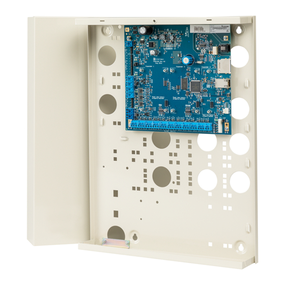
Installing the control panel See Figure 4 below for overall details of a TS-CHPLUS ChallengerPlus panel installed in a TS0307 Universal Enclosure. Figure 4: Challenger panel board mounted in enclosure (models TS-CHPLUS) Figure 4 legend Item Description Enclosure mounting points... -
Page 16: Installation Procedures
25 mm between the enclosure and any side wall or ceiling. • ChallengerPlus panels are powered and earthed via a 16 Volt AC plug pack. • A power outlet (GPO) must be in proximity to the panel. Only qualified Electricians should provide a GPO. -
Page 17: Board Details
(for example, Figure 4 on page 9, item 2). 3. Slide the board’s terminal connectors together and mount them to the board. Board details See Figure 5 below for the TS-CHPLUS ChallengerPlus panel. Figure 5: Model TS-CHPLUS board details ChallengerPlus Installation and Quick Programming Manual... - Page 18 Figure 5 legend Item Description Connect one end of each LAN cable shield to the ring terminal and fasten with M3 screw to the Challenger panel board’s LAN earth terminal. Connect the power terminals to a 16 Volt AC plug pack. Maximum current drawn by the panel with no peripheral devices connected is approximately 200 mA.
- Page 19 Rx2 receive LED flashes to indicate remote units on LAN 2 are replying to polling. TERM link for LAN 2. See “RS-485 LAN” on page 15. See Figure 6 on page 14 for connection details for terminal blocks J1 to J5. ChallengerPlus Installation and Quick Programming Manual...
-
Page 20: Application Notes
Figure 6: Connection details for terminal blocks J1 to J5 Application notes 16 VAC plug pack • Use the 16 VAC plug pack supplied with the Challenger panel. • When installing plug packs, do not power the unit until you have terminated all necessary wires and checked that you do not have a short circuit. - Page 21 LAN to around 220 Ω in order to minimise noise. The termination resistor may be external or onboard (devices with an onboard resistor use a link or a DIP switch to set the LAN termination to ON). ChallengerPlus Installation and Quick Programming Manual...
- Page 22 A Challenger LAN should have only two devices with the LAN termination set to ON (or the LAN termination resistor fitted): • In a straight LAN configuration (Figure 1 on page 5) the termination is ON at the Challenger panel and the most distant device. •...
- Page 23 (Challenger) zone input circuits. If connecting the Challenger panel to other configurations of zone input circuits, the placement and values of EOL resistors may differ. In any case, you must test the installation to avoid unexpected results. ChallengerPlus Installation and Quick Programming Manual...
- Page 24 When the system is used in two-state configuration, inputs can only report sealed and unsealed states. This prohibits the use of input types that need to detect short or open states. See the ChallengerPlus Programming Manual for details. Special zone input types Zone inputs programmed as area control type inputs can also be used to turn areas on and off (as opposed to entering a PIN on a keypad).
- Page 25 Alarm is generated when input changes from sealed to open or short. • The normal state of the key switch is sealed • When unsealed the input is isolated, no alarm generated • Open circuit generates a tamper alarm • Short circuit generates an alarm ChallengerPlus Installation and Quick Programming Manual...
- Page 26 Telephone connection See Figure 5 on page 11, item 13. Some Challenger panel models are supplied with a pre-wired 604 plug for connection to a 611 socket for PSTN in connection mode 3 for dialler reporting formats (see Figure 11 below). Figure 11: Line connections for 611 socket for dialler reporting formats J15 serial port See Figure 5 on page 11, item 20.
-
Page 27: Initial Programming
Refer to the documentation provided with the management software for additional details. Challenger panel programming is described in detail in ChallengerPlus Programming Manual. This section describes the following programming steps that are part of the installation process: ... - Page 28 This manual describes the Challenger programming that you may need for basic system setup. Refer also to: • ChallengerPlus Programming Manual for details of Challenger system programming via the Install menu. • ChallengerPlus Administrators Manual for details of Challenger programming and operation via the User menu.
- Page 29 Card to code time is set to 8 seconds • Minimum area search time is set to 0 minutes • Maximum area search time is set to 0 minutes • Maximum twin trip time is set to 60 seconds ChallengerPlus Installation and Quick Programming Manual...
- Page 30 Install menu option Description 7. System options Program the system options if the default values are not suitable. The default values for system options are: • Film Low is set to 800 • Film Out is set to 1100 • Input tamper monitoring is selected •...
- Page 31 43. Automation status Check and control automation zones from any LCD RAS. 44. Standard lifts Program up to two lifts. Each lift up to ten floors. 45. Standard doors Program up to 32 doors. ChallengerPlus Installation and Quick Programming Manual...
-
Page 32: Clearing The Memory
Clearing the memory When installing a new panel, or upgrading the firmware on an existing panel, we recommend that you default the panel before programming it. Note: All custom programming will be erased. Back up any data you need before using these procedures. - Page 33 12. Holidays must also be assigned one or more holiday types (1 to 8). Decide what each holiday type will be used for, and record the purpose in the Holidays and Holidays Types worksheets (see the ChallengerPlus Administrators Manual). 13. Program time zones via Install menu option 13 Time Zones.
-
Page 34: Working With Multi-Area Systems
Working with multi-area systems New or defaulted Challenger panels can arm and disarm areas 1 to 99. This functionality is accomplished via Area Group 1, which contains all areas. Area Group 1 is used in the following Alarm Groups: • Alarm Group 2–Master RAS or Door •... -
Page 35: Enabling Communications
Ten communication paths are available for simultaneous management software connections, reporting via onboard dialler, printing events, and so on. The status of each path can be quickly displayed via RAS to facilitate installation and troubleshooting. ChallengerPlus Installation and Quick Programming Manual... - Page 36 A communication path can be assigned a priority number in the range 1 to 10 (the highest priority being 1), or 0 for no priority assignment. Also, a communication path can be designated as a backup for another communication path. A Challenger panel has default values programmed for the following communications paths: •...
- Page 37 12. In CTPlus, select Panel programming > Panels from the Navigation bar to open the Panels form. button on the form’s toolbar to create a new panel record. 13. Click the New Enter a description for the new panel record. ChallengerPlus Installation and Quick Programming Manual...
- Page 38 The new entry for the panel in the connections list should indicate that the panel is enabled and online. Example 3: Programming an UltraSync connection The steps required to connect management software to a ChallengerPlus panel via UltraSync are: Get the ChallengerPlus panel’s serial number ...
- Page 39 Follow these steps to get the serial number from a connected Challenger panel: Click the Panels button on the Panel programming ribbon tab to open the Panels form. Select the required Challenger panel. On the Communication tab, note the Serial number field. ChallengerPlus Installation and Quick Programming Manual...
- Page 40 CTPlus or the keypad. Method1: CTPlus o Connect to CTPlus via USB o Go to Operation -> Status and Control o Right Click on the ChallengerPlus Panel o Go to Diagnostics-> Diagnostics o Select “Comms device” for Diagnostics type...
- Page 41 Subnet Mask: 255.255.255.000 (dhcp) IP(1): Press Enter o Press [ENTER] to display the Gateway address: Gateway Add: 198.168.0.00 (dhcp) IP(1): Press Enter o Press [ENTER] to display the DNS address 1: DNS 1 Add: 198.168.056.001 (dhcp) IP(1): ChallengerPlus Installation and Quick Programming Manual...
- Page 42 o Press [ENTER] to display the DNS address 2: DNS 2 Add: 198.168.056.002 (dhcp) IP(1): o Press [ENTER] to display the Ethernet interface’s MAC address: Eth: MAC Addr 00:17:55:EE:78:d9 Press Enter...
- Page 43 GSM) to CTPlus via UltraSync. o Allow programming if any area is armed: If not enabled, user cannot modify the ChallengerPlus database using CTPlus until all areas are disarmed. o Allow remote control: If not enabled, users cannot run CTPlus operations (open door, lock door etc.) via UltraSync connection.
- Page 44 Challenger panel from CTPlus To identify and authorize the user accessing CTPlus via UltraSync: Click the Panels button on the Panel programming ribbon tab. Click the New button on the form’s toolbar. On the Definition tab; Tick the “Enable” checkbox. ...
- Page 45 Enter the Challenger panel’s serial number in the Serial number field. Enter the Challenger panel’s passcode in the Passcode field (as configured in UltraSync options) Click the Save button on the form’s toolbar. ChallengerPlus Installation and Quick Programming Manual...
-
Page 46: Programming Users
Unless you will be programming (adding) the system’s users yourself, you will need to program at least one administrator who will be able to program additional users. See ChallengerPlus Administrators Manual for details. The default values for User 50, the master code, are: •... -
Page 47: Appendix C: Operating Temperature
If the Challenger is to operate for prolonged periods in an environment with an ambient temperature above 40°C, de-rate the user current drawn from the NAC according to the chart in Figure 15 below. Figure 15: Power derating chart ChallengerPlus Installation and Quick Programming Manual...
Need help?
Do you have a question about the ChallengerPlus and is the answer not in the manual?
Questions and answers