
Related Manuals for Exsys EX-1309-T


Summary of Contents for Exsys EX-1309-T
- Page 1 Anleitung EX-1309-T 1x RS-232/422/485 zu USB 2.0 1x RS-232/422/485 to USB 2.0 Vers. 1.1 / 09.04.19 Manual...
-
Page 2: Table Of Contents
EX-1309-T Inhaltsverzeichnis Beschreibung ······················································································ 3 Lieferumfang ······················································································ 3 Aufbau und Anschlüsse ······································································ 4-5 3.1 Aufbau ······································································································ 4 3.2 Anschlüsse ······························································································ 4-5 Dipp-Schalter Einstellungen ································································ 6-9 Hardware Installation ··········································································· 10 Treiber Installation ········································································· 10-11 Technische Daten ··············································································· 11 Index Description ························································································ 12 Extent of Delivery ···············································································... -
Page 3: Beschreibung
• Unterstützt Windows 9.x ME/ 2000/ XP/ Vista/ 7/ 8.x/ 10/ Server 20xx/ Linux/ MAC • Zertifiziert für 2. Lieferumfang Bevor Sie die EX-1309-T an Ihren PC anschließen, überprüfen Sie bitte zuerst den In- halt der Lieferung: • EX-1309-T •... -
Page 4: Aufbau Und Anschlüsse
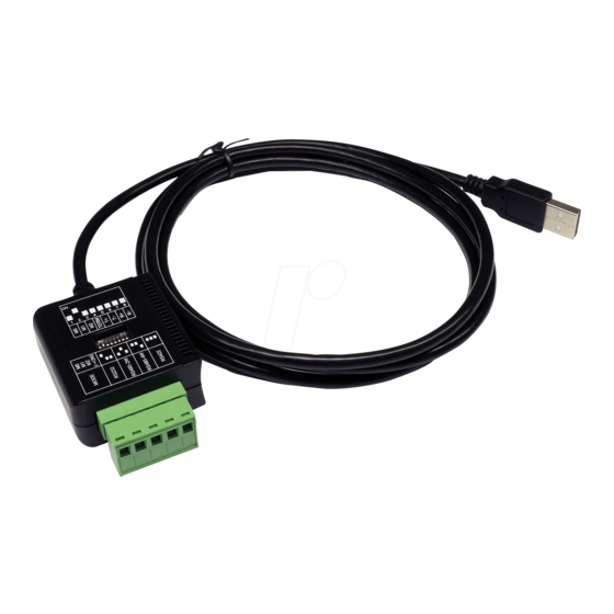
Deutsch EX-1309-T 3. Aufbau und Anschlüsse 3.1 Aufbau Dipp-Schalter zur Einstellung der Übertragungsarten USB A-Stecker S1: 1 x 5 Pin Seriell Terminal Block 3.2 Anschlüsse USB A-Stecker: USB 2.0 A-Stecker Signal Signal DATA+ DATA-... - Page 5 EX-1309-T Deutsch 3. Aufbau und Anschlüsse 3.2 Anschlüsse 5 Pin Terminal Block: TB5 (EX-1309-T) Endgerät TB5 (EX-1309-T) Endgerät 1 RXD 1 DCD 2 DCD 2 RXD 1 TXD+ 1 TXD- 3 TXD 3 TXD 2 TXD- 2 TXD+ 4 DTR...
-
Page 6: Dipp-Schalter Einstellungen
EX-1309-T 4. Dipp-Schalter Einstellungen An der Unterseite der EX-1309-T befindet sich ein Dipp-Switch mit dem Sie die verschie- denen Übertragungsarten einstellen können. Der Dipp-Switch besteht aus 8 Pins. Wobei die ersten drei Pins (M0, M1 & M2) für die Übertragungsarten zuständig sind. Der Pin 4 ist zum ein/-ausschalten des Terminator. - Page 7 EX-1309-T Deutsch 4. Dipp-Schalter Einstellungen Einstellen der Übertragungsarten Jumper Beschreibung 2 Draht RS-485 4 Draht RS-485 Terminator ein/-ausschalten Ausgeschaltet Eingeschaltet...
- Page 8 Deutsch EX-1309-T 4. Dipp-Schalter Einstellungen Terminator für RS-485 2-Draht Mode Terminator für RS-422 und RS-485 4-Draht Mode...
- Page 9 EX-1309-T Deutsch 4. Dipp-Schalter Einstellungen Bias Resistor ein-/ausschalten Achtung! Im RS-232 Modus müssen diese 4 Pins auf “OFF“ gestellt werden!
-
Page 10: Hardware Installation
Deutsch EX-1309-T 5. Hardware Installation Beachten Sie bitte die folgenden Installationshinweise. Da es große Unterschiede zwi- schen PC‘s gibt, können wir Ihnen nur eine generelle Anleitung zum Einbau geben. Bei Unklarheiten halten Sie sich bitte an die Bedienungsanleitung Ihres Computersystems. -
Page 11: Technische Daten
EX-1309-T Deutsch 6. Treiber Installation LINUX Die Linux Treiber befinden sich im Verzeichnis “D:\USB_to_IO\FTDI\Linux x86_64“ auf der Treiber CD. Sie werden unter den meisten Linux Versionen unterstützt. Da sich die einzelnen Distributionen und Kernelversionen sehr voneinander unterscheiden, kön- nen wir Ihnen leider keine Installationsanweisung geben. Bitte halten Sie sich an die Installationsanweisung für USB Ports Ihrer Linux Version. -
Page 12: Description
(e.g. Modem, Plotter etc.). The USB to Serial module design utilizes the Chip- Set FTDI with 16C550 UART. The EX-1309-T is Hot Plug & Play compatible. It is not possible to change the address or IRQ settings manually, they will be obtained auto- matically by the operating system. -
Page 13: Layout And Connections
EX-1309-T English 3. Layout and Connections 3.1 Layout Dipp-Switch to set the vari- ous types of the transmission USB A-Connector S1: 1 x 5 Pin Serial Terminal Block 3.2 Connections USB A-Connector: USB 2.0 A-Connector Signal Signal DATA+ DATA-... - Page 14 English EX-1309-T 3. Layout and Connections 3.2 Connections 5 Pin Terminal Block: TB5 (EX-1309-T) Device TB5 (EX-1309-T) Device 1 RXD 1 DCD 2 DCD 2 RXD 1 TXD+ 1 TXD- 3 TXD 3 TXD 2 TXD- 2 TXD+ 4 DTR...
-
Page 15: Dipp-Switch Settings
English 4. Dipp-Switch Settings At the bottom of the EX-1309-T you will find one Dipp-Switch. With this Dipp-Switch you can set the various types of transmission. The Dipp-Switch consists of 8 pins. The first three pins (M0, M1 & M2) are responsible for the transmission. Pin 4 is used for turn ON/OFF the Terminator. - Page 16 English EX-1309-T 4. Dipp-Switch Settings Set the transmission modes Jumper Description RS-485 2-wire RS-485 4-wire Terminator ON/OFF...
- Page 17 EX-1309-T English 4. Dipp-Switch Settings Terminator for RS-485 2-wire mode Terminator for RS-422 and RS-485 4-wire mode...
- Page 18 English EX-1309-T 4. Dipp-Switch Settings Bias Resistor ON/OFF Attention! For RS-232 operation, these pins must be set to “OFF“!
-
Page 19: Hardware Installation
5. Hardware Installation Because there are large differences between PC’s, we can give you only a general instal- lation guide for the EX-1309-T. Please refer your computers reference manual whenever in doubt. 1. At first connect the USB cable (A-Plug) to the USB A-Port at your PC. -
Page 20: Technical Information
English EX-1309-T 6. Driver Installation LINUX There are drivers available for Linux. The drivers are located in the folder “D:\USB_to_IO\FTDI\Linux x86_64“ on the driver CD. They are supported by the most versions of Linux. Because each individual distribution and kernel version of Linux is different, sadly we cant provide a installation instruction.
Need help?
Do you have a question about the EX-1309-T and is the answer not in the manual?
Questions and answers