Advertisement
Quick Links
DIP-SWITCH & CONNECTORS
DIP-Switch
Description
RS-485 2-wire Mode
(Factory Setting)
RS-485 4-wire Mode
RS-422 Mode
RS-232 Mode
(Note: Pin 1 and Pin 2 must be set to
OFF to operate in the
RS-232 mode)
RS-232 Pin Assignments:
RS-232 Cable Wiring
DB 9M
DB9 (EX-1333VIS)
9 Pin Serial Connector
1 DCD
Pin
Signal
Pin
Signal
2 RXD
3 TXD
1
DCD
6
DSR
4 DTR
2
RXD
7
RTS
5 GND
3
TXD
8
CTS
6 DSR
4
DTR
9
RI
7 RTS
5
GND
8 CTS
RS-422/485 Pin Assignments:
DB 9M
RS-422 Cable Wiring
DB9 (EX-1333VIS)
9 Pin Serial Connector
1 TXD-
Pin
Signal
Pin Signal
2 TXD+
1
TXD- (DATA-)
6
NC
3 RXD+
2
TXD+ (DATA+)
7
NC
4 RXD-
3
RXD+
8
NC
5 GND
4
RXD-
9
NC
5
GND
RS-485 2-wire Cable Wiring
RS-485 4-wire Cable Wiring
DB9 (EX-1333VIS)
RS-485 (Device)
DB9 (EX-1333VIS)
1 TXD-
1 TXD-
1 TXD-
2 TXD+
2 TXD+
2 TXD+
3 RXD+
3 RXD+
3 RXD+
4 RXD-
4 RXD-
4 RXD-
5 GND
5 GND
5 GND
5
HARDWARE INSTALLATION
Because there are large differences between PC's, we can give you only a general installation
guide for the EX-1333VIS. Please refer your computers reference manual whenever in doubt.
1.
Connect the supplied USB 2.0 cable to the USB 2.0 B-Port of the EX-1333VIS.
2.
Now connect the other end (A-Connector) of the supplied USB 2.0 cable to the USB A-Port
on your PC.
3.
When you are ready you can start your PC and continue with „Driver Installation".
DRIVER INSTALLATION
After the hardware installation, the operating system will recognize the device automatically and
install the drivers. If the driver should not be installed automatically, please download the driver
from our homepage (www.exsys.de / www.exsys.ch) first. Now select the folder with your
operating system and install the driver. Follow the hardware assistant and finish the installation.
Important! Restart your PC in any case after installing the drivers.
CHECK INSTALLED DRIVER
Open the >Device manager<. Now you should see at „Ports (COM & LPT)" and „USB-
Controller" the following new entries:
RS-232 (Device)
1 DCD
2 RXD
3 TXD
4 DTR
If you see these or a similar information's the device is installed correctly.
5 GND
6 DSR
7 RTS
8 CTS
CLEANING
For cleaning please use only a dry fluff less cloth and remove the dirt with gently pressure. In
the area of the connectors please make sure that no fibres from the cloth remain in the
connectors. Attention! Never use a moist or wet cloth for cleaning!
RS-422 (Device)
1 TXD-
2 TXD+
3 RXD+
4 RXD-
5 GND
RS-485 (Device)
1 TXD-
2 TXD+
3 RXD+
Germany:
Switzerland:
EXSYS Vertriebs GmbH
EXSYS Vertriebs GmbH
4 RXD-
Industriestrasse 8
Dübendorfstrasse 17
61449 Steinbach
8602 Wangen
5 GND
www.exsys.de
www.exsys.ch
Italy:
EXSYS Italia Srl
Via Belvedere, 45/B
I-22100 Como
www.exsys.it
6
Anleitung
Anleitung
Vers. 1.0, 21.12.22
Vers. 1.1 / 22.08.24
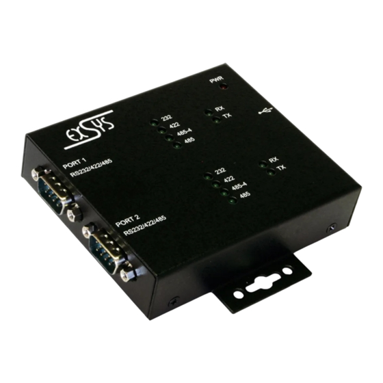
AUFBAU
Mode LED für Port 1
TX/RX LED für Port 1
Betriebs LED
Port 1
Port 2
Mode LED für Port 2
TX/RX LED für Port 2
BESCHREIBUNG & TECHNISCHE DATEN
Der EX-1333VIS USB zu RS-232/422/485 Konverter im Metallgehäuse stellt zwei serielle RS-
232, 422, oder 485 High Performance UART 16C550 Schnittstellen mit 15KV ESD
Überspannungsschutz und 2.5KV Isolation zur Verfügung. Er wurde entwickelt um serielle
Geräte am USB 1.1 bis 3.2 Gen 2 Bus eines PCs, Servers oder einer Workstation
anzuschliessen. Das mitgelieferte Kabel EX-K1542V kann ohne Schraubenzieher mit
Rändelschrauben am EX-1333VIS befestigt werden. Ein selbstständiges Lösen des Kabels ist
somit nicht mehr möglich. Durch die einfache Installation am USB-Port muss der Rechner nicht
geöffnet werden und der Konverter kann bei laufendem Betrieb installiert werden. Mit dem
optional erhältlichen DIN-Rail-Kit (EX-6099) kann der EX-1333VIS auf eine Trägerschiene in
einem 19" Rack installiert werden.
Kompatibilität:
USB 1.1, 2.0 & 3.2
Betriebssysteme:
Windows 9.x / ME / 2000 / XP / Vista / 7 / 8.x / 10 / 11 / Server 20xx /
Linux / MAC
Anschlüsse:
2x 9 Pin Stecker Seriell RS-232/422/485, 1x USB 2.0 B-Buchse
Lieferumfang:
EX-1333VIS, USB 2.0 Kabel (verschraubbar), Anleitung
DIP-SCHALTER & ANSCHLÜSSE
Es gibt zwei 4-Pin DIP-Schalter auf der Unterseite der EX-1333VIS. Jeder DIP-Schalter ist für
einen seriellen Port zuständig. Pin 1 und Pin 2 (markiert mit M1 und M0) haben die Funktion
zwischen den drei Modis RS-232, RS-422 und RS-485 umzuschalten. Pin 3 und Pin 4 (markiert
mit TERM ON) haben die Funktion die Abschlusswiederstände für die RS-422/485 Modis ein
oder auszuschalten.
M1
RS-232/422/485 Mode Schalter
M0
TERM ON
Schalter für Abschlusswiederstände
TERM ON
1
EX-1333VIS
USB B-Buchse
(verschraubbar)
Advertisement

Related Manuals for Exsys EX-1333VIS


Summary of Contents for Exsys EX-1333VIS
- Page 1 EX-1333VIS. Please refer your computers reference manual whenever in doubt. DIP-Switch Description Connect the supplied USB 2.0 cable to the USB 2.0 B-Port of the EX-1333VIS. Vers. 1.0, 21.12.22 Vers. 1.1 / 22.08.24 Now connect the other end (A-Connector) of the supplied USB 2.0 cable to the USB A-Port RS-485 2-wire Mode on your PC.
- Page 2 5 GND 5 GND running. With the optional DIN-Rail kit (EX-6099), the EX-1333VIS can be mounted on a DIN- 6 DSR 6 DSR Sind diese oder ähnliche Einträge vorhanden, ist der EX-1333VIS richtig installiert.
Need help?
Do you have a question about the EX-1333VIS and is the answer not in the manual?
Questions and answers