Table of Contents
Advertisement
Quick Links
Betriebsanleitung
User Manual
Aktuelle Produktinformation: www.knick.de
Latest Product Information: www.knick.de
Analysenmesssystem
Protos II 4400(X) / Protos 3400(X)
Protos 3400(X)
Process Analysis System
Protos COMFF 3400(X)-085
Messmodul Protos CONDI 3400 (X)-051
Deutsch
Communication Module
zur Leitfähigkeitsmessung mit induktiven Sensoren
Communication Unit for FOUNDATION Fieldbus
The Art of Measuring.
Advertisement
Table of Contents

Related Manuals for Knick Protos COMFF 3400-085


Summary of Contents for Knick Protos COMFF 3400-085
- Page 1 Protos II 4400(X) / Protos 3400(X) Protos 3400(X) Process Analysis System Betriebsanleitung Protos COMFF 3400(X)-085 Messmodul Protos CONDI 3400 (X)-051 User Manual Deutsch Communication Module zur Leitfähigkeitsmessung mit induktiven Sensoren Communication Unit for FOUNDATION Fieldbus Aktuelle Produktinformation: www.knick.de Latest Product Information: www.knick.de...
-
Page 2: Returns
Trademarks The following trademarks are used in this document without further marking: Calimatic®, Protos®, Sensocheck®, Sensoface®, Unical®, VariPower®, Ceramat®, SensoGate® are registered trademarks of Knick Elektronische Messgeräte GmbH & Co. KG, Germany Memosens® is a registered trademark of Endress+Hauser Conducta GmbH & Co. KG, Germany... -
Page 3: Table Of Contents
Table of Contents Protos COMFF 3400(X)-085 Module Returns ............................2 Disposal ............................2 Trademarks ........................... 2 Intended Use ....................5 Safety Instructions ..................6 Operation in Explosive Atmospheres: COMFF 3400X-085 Module ......6 Firmware Version .................... 7 Foundation Fieldbus (FF) Technology ............8 Bus Communication ........................ - Page 4 Table of Contents Protos COMFF 3400(X)-085 Module DI Function Blocks ........................31 DI 1: Unical Status ......................31 DI 2: CONTACTS / LOCK Status / ENABLE Request ..........31 DI 3: Unical Messages.....................32 Explanation of Unical Messages: Maintenance Request........32 Explanation of Unical Messages: Failure ..............33 DI 4: Unical Step .......................33 DO Function Blocks .........................34 DO 1: HOLD Control .......................34...
-
Page 5: Intended Use
Intended Use The module is a communication unit for Foundation Fieldbus. The COMFF 3400X-085 module is intended for operation in locations subject to explosion hazards which require equipment of Group II, device category 2(1), gas/dust. -
Page 6: Safety Instructions
• In hazardous locations the device shall only be cleaned with a damp cloth to prevent electrostatic charging. Maintenance The Protos modules cannot be repaired by the user. For inquiries regarding module repair, please contact Knick Elektronische Messgeräte GmbH & Co. KG at www.knick.de. -
Page 7: Firmware Version
Firmware Version COMFF 3400(X)-085 module firmware: Firmware version 2.x Module compatibility COMFF 3400-085 COMFF 3400X-085 Protos 3400 from FRONT firmware version 7.0 Protos 3400X from FRONT firmware version 7.0 Protos II 4400 from FRONT firmware version 1.0.0 Protos II 4400X from FRONT firmware version 1.0.0 Query Current Device Firmware/Module Firmware When the device is in measuring mode: Press menu key, open Diagnostics menu: Device Description... -
Page 8: Foundation Fieldbus (Ff) Technology
Foundation Fieldbus (FF) Technology Foundation Fieldbus (FF) is a digital communication system that connects different field devices over a common cable and integrates them into a control system. Its application range covers manufacturing, process, and building automation. As fieldbus standard according to EN 61158-2 (IEC 1158-2) the Foundation Fieldbus ensures the communication of different devices over one bus line. -
Page 9: Bus Communication
Foundation Fieldbus (FF) Technology Bus Communication Foundation Fieldbus (FF) permits cyclic and acyclic services: Cyclic Services - Scheduled Communication: • are used for transmission of measurement data with status information. The Link Active Scheduler maintains a list of transmission times for all data in all devices that need to be cyclically transmitted. -
Page 10: Terminal Plate
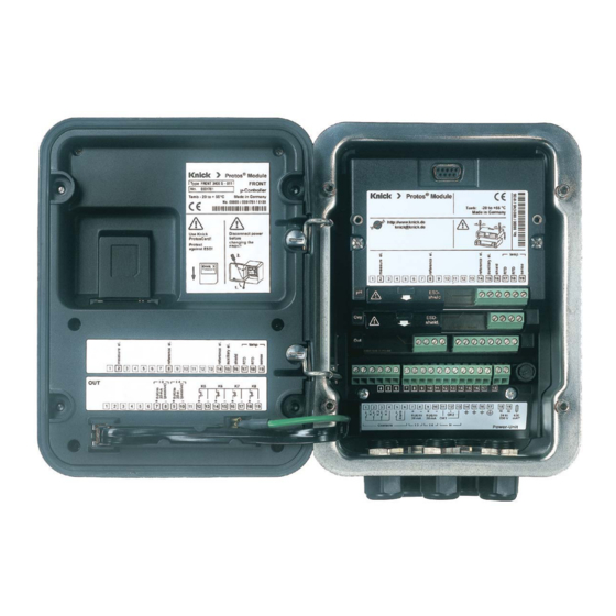
Terminal Plate Terminal Plate COMFF 3400-085 Module: Attaching the Terminal Plates The terminal plates of the lower modules can be sticked to the inner side of the door. This facilitates maintenance and service. -
Page 11: Installing The Module
Installing the Module CAUTION! Electrostatic discharge (ESD). The modules' signal inputs are sensitive to electrostatic discharge. Take measures to protect against ESD before inserting the module and wiring the inputs. Note: Strip the insulation from the wires using a suitable tool to prevent dam- age. -
Page 12: Foundation Fieldbus Installation
Foundation Fieldbus Installation Basic build-up of a PROFIBUS system: Control room Ethernet or HSE Fieldbus Linking Device H1 Fieldbus e.g. Protos 3400(X) with COMFF 3400(X)-085 Electrical connection between module and Foundation Fieldbus is in accor- dance with FISCO (Fieldbus Intrinsically Safe Concept, www.fieldbus.org). COMFF 3400(X)-085 module Fieldbus cable Shield... - Page 13 Resource Block Channel AI TB 1 AI 1 Transducer Analog Input Module Selection Block AI 2 Module I Analog Input Module II AI 3 Calc. Block I Analog Input Calc. Block II AI 4 Analog Input Records Calibration AI TB 2 AI 5 Transducer Analog Input...
-
Page 14: Communication Model
Communication Model See diagram on previous side All variables and parameters of the transmitter are assigned to blocks. Resource Block (RB) Describes the transmitter characteristics (manufacturer, device name, operating status, general status). Analog Input Block (AI) 2 x 4 Analog Input Function Blocks provide for cyclic transmission of measured values (currently measured value with status, alarm limits, freely selectable process variable from up to 2 measuring modules). -
Page 15: Ai-Tb Configuration On The Device
AI-TB Configuration on the Device Assigning process variables to Analog Input Blocks on the device Assigning process variables to Menu Display Analog Input Blocks Open parameter setting 25.6° C 7.00 pH From the measuring mode: Menu selection Press menu key to select menu. Select parameter setting using arrow keys, confirm by pressing enter. -
Page 16: Bus Activation
AI-TB Configuration on the Device Assigning process variables to Analog Input Blocks on the device Assigning process variables to Menu Display Analog Input Blocks Select AI-TB configuration: 25.6 °C 7.00 pH Assign each process variable to one AI TB1 configuration (Administrator) of the 4 Analog Input Blocks per TB. -
Page 17: For Copy: Individual Settings
For Copy: Individual Settings Assigning process variables to Analog Input Blocks on the device AI Block Process variable assigned AI-TB1 Selected measuring module Analog Input Block AI 1 Analog Input Block AI 2 Analog Input Block AI 3 Analog Input Block AI 4 AI-TB2 Selected measuring module Analog Input Block AI 5... -
Page 18: Offline Configuration
Offline Configuration The AI blocks are divided into two groups (AI Transducer Blocks) which are each assigned to one measuring module. This allows control of functions in the measuring modules. If there is only one measuring module, both AI TBs can be assigned to the same module so that they can output more measured values cyclically. - Page 19 AI TB 1 (AI Transducer Block) As an example, this block was assigned to the Module I (measuring module, pH). All process variables available from this module can be assigned to the AI channels. (See chapter “Process Variables Available for Fieldbus“ for assignment of process variables): Select process variable Channel...
-
Page 20: Initial Commissioning
Commissioning and Configuration Initial Commissioning Supply the device with power. Open the configuration program of the control system. Load CFF file and DD. After the first connection establishment, the device answers as follows: Device ID Assign the desired name (PD_TAG) to the field device. Setting the Resource Block (RB) parameters Set the MODE_BLK. -
Page 21: Analog Input Blocks
Analog Input Blocks Analog Input Blocks The module provides 8 analog input blocks (AI 1 ... AI 8). An Analog Input Block contains the signal processing options for the process variable supplied from the Transducer Block. The following parameters are available: Example: In the Protos AI 1 is set to pH value, AI 2 is set to temperature: Settings in AI 1:... -
Page 22: Configuration Of Ai Tb
Configuration of AI TB (Example: Configuration via NI-FBUS Configurator / National Instruments) After connection of the Protos COMFF 3400-085 module to the Foundation Fieldbus the NI-FBUS Configurator shows this block overview (default setting: Fieldbus address 22) Move all required AI blocks to the Function Block Application and start... -
Page 23: Configuration With Foundation Fieldbus
For network projecting, you require the CFF file (Common File Format). These files can be obtained from: • the included CD • internet: www.knick.de • Foundation Fieldbus: www.fieldbus.org. Identifying the Transmitter There are several possibilities to identify a FF transmitter in the network. -
Page 24: Commissioning And Configuration
Commissioning and Configuration Corresponding to example given on Page 18, "Offline Configuration" For parameter changes, you must set MODE_BLK/TARGET to OOS (Out of Service) since otherwise the error message NIF_ERR_WRONG_MODE_FOR_ REQUEST would appear for [Write Changes]. Analog_Input_1 "Process" card: CHANNEL Module 1 - Channel 1 "Scaling"... - Page 25 Commissioning and Configuration Analog_Input_5 "Process" card: CHANNEL Module 2 - Channel 1 "Scaling" card: XD_SCALE/UNITS_INDEX OUT_SCALE/UNITS_INDEX L_TYPE Direct Button [Write Changes] Button [Auto] Analog_Input_6 "Process" card: CHANNEL Module 2 - Channel 2 "Scaling" card: XD_SCALE/UNITS_INDEX °C OUT_SCALE/UNITS_INDEX °C L_TYPE Direct Button [Write Changes] Button...
- Page 26 Commissioning and Configuration An external pressure sensor can be connected to the Analog Output Block (AO) through the Foundation Fieldbus network. Analog_Output1 "Process" card: CHANNEL Channel 21 (Analog Output Value) "Scaling" card: XD_SCALE/EU_100 9999 XD_SCALE/UNITS_INDEX mbar OUT_SCALE/EU_100 9999 OUT_SCALE/UNITS_INDEX mbar "Limits"...
- Page 27 Commissioning and Configuration Discrete_Input_1 "Process" card: CHANNEL Channel 11 Discrete Input Value Button [Write Changes] Button [Auto] Discrete_Input_2 "Process" card: CHANNEL Channel 12 Discrete Input Value Button [Write Changes] Button [Auto] Discrete_Input_3 "Process" card: CHANNEL Channel 13 Discrete Input Value Button [Write Changes] Button...
-
Page 28: Calibration Protocols
Commissioning and Configuration Calibration Protocols Calibration Protocols The protocols are transmitted in the AI TBs in binary form. The DD provides a method for converting them to a readable format. The method can be started with “Read protocol“ in the “Protocol“ menu of the AI TB. Each AI TB of the FF module has a ring buffer which can store up to three pro- tocols. -
Page 29: Parameters Of Ai Transducer Blocks
Parameters of AI Transducer Blocks All blocks correspond to the “FF-007-5.0 Specifications”. Only the two AI-TB blocks have been extended (Index 14 ... 39). AI-TB1 and AI-TB2 can be assigned to different measuring modules in the Protos. Description Index Parameter Standard parameters AITB ST_REV... -
Page 30: Function Block Ao
Parameters of AI Transducer Blocks Index Parameter Description Manufacturer-specific extensions: Protocols PROTOCOL_STATUS Status PROTOCOL_DATA_0 Binary protocol data, part 1 PROTOCOL_DATA_1 PROTOCOL_DATA_2 PROTOCOL_DATA_3 PROTOCOL_DATA_4 PROTOCOL_DATA_5 PROTOCOL_DATA_6 PROTOCOL_DATA_7 PROTOCOL_DATA_8 PROTOCOL_DATA_9 PROTOCOL_DATA_A PROTOCOL_DATA_B PROTOCOL_DATA_C PROTOCOL_DATA_D PROTOCOL_DATA_E PROTOCOL_DATA_F Binary protocol data, part 16 PROTOCOL_CONFIRM Save protocol A ring buffer for up to 3 protocols is implemented in the module The DD includes a method for presenting the protocol in a readable manner. -
Page 31: Di Function Blocks
DI Function Blocks DI 1: Unical Status Meaning Probe in MEASURE position (PROCESS) Probe in SERVICE position Service switch actuated Unical alarm Unical program active No program Program: Cleaning Program: Cal 2point Program: Cal 1point Program: Parking Program: USER 1 Program: USER 2 Program: Service DI 2: CONTACTS / LOCK Status / ENABLE Request... -
Page 32: Di 3: Unical Messages
DI Function Block Unical Messages Unical with Protos II 4400(X) from FRONT firmware version 02.xx.xx DI 3: Unical Messages Meaning Probe maintenance request Media adapter maintenance request Unical basic device maintenance request Medium maintenance request Probe failure Media adapter failure Unical basic device failure Calibration / Communication error Explanation of Unical Messages: Maintenance Request... -
Page 33: Explanation Of Unical Messages: Failure
Unical Messages, Unical Step Unical with Protos II 4400(X) from FRONT firmware version 02.xx.xx Explanation of Unical Messages: Failure Probe failure U 230 Probe limit position MEASURE (PROCESS) U 227 Probe limit position SERVICE Media adapter failure U 194 Buffer I empty U 195 Buffer II empty U 196... -
Page 34: Do Function Blocks
DO Function Blocks DO 1: HOLD Control Meaning System HOLD Reserved Reserved Reserved Reserved Reserved Reserved Reserved DO 2: PARSET Meaning Parameter set B (internal) Parameter set not from card Parameter set 1 (card) Parameter set 2 (card) Parameter set 3 (card) Parameter set 4 (card) Parameter set 5 (card) Reserved... -
Page 35: Do 3: Unical Control
DO Function Blocks DO 3: Unical Control Meaning Reserved Probe in SERVICE position (MEASURE = 0) Manual, Time control Off (Auto, Time control On = 1) Reserved Reserved No program start Program: Cleaning Program: Cal 2point Program: Cal 1point Program: Parking Program: USER 1 Program: USER 2 No program start... -
Page 36: Enable / Lock Via Dcs
Enable / Lock via DCS NOTICE! Control system programming required by customer Enable / Lock Protos for on-site calibration via DCS. The DI 1 and DO 4 function blocks are used for communicating with the DCS (control system programming required by customer). Step 1: The user calls the cal menu, for example, on the device. -
Page 37: Function Control Matrix
Function Control Matrix Controlling parameter set selection / KI recorder via Fieldbus H1 Parameter setting/Administrator level/System control/Function control matrix Menu Display Control via Foundation Fieldbus 7.00 pH Open parameter setting 25.6 °C From the measuring mode: Menu selection Press menu key to select menu. Select parameter setting using arrow keys, press enter to confirm. -
Page 38: Specifications
Specifications Protos COMFF 3400(X)-085 Foundation Fieldbus FF-H1 COMFF 3400X-085: Digital communication in hazardous areas via current modulation (Ex ia IIC) Physical interface According to IEC 61158-2 Transfer rate 31.25 kbits/s Communication protocol FF-816 Profile FF_H1 (Foundation Fieldbus) Bus address Visible on the device but not adjustable Supply voltage (FISCO) Bus supply: 9 …... - Page 39 Specifications General data Explosion protection See certificates or www.knick.de (Ex version of module only) RoHS conformity According to EU directive 2011/65/EU EN 61326-1, EN 61326-2-3 NAMUR NE 21 Emitted interference Industrial applications* (EN 55011 Group 1 Class A) Interference immunity...
-
Page 40: Process Variables Available For Fieldbus
Process Variables Available for Fieldbus Process variables which can be assigned to Analog Input Blocks (AI): pH Modules Measured value Unit of measure pH value Electrode voltage Electrode potential (ORP) rH value Glass impedance Reference impedance Temperature °C Temperature °F pH zero point pH slope mV/pH... -
Page 41: Process Variables Available For Fieldbus
Process Variables Available for Fieldbus Process variables which can be assigned to Analog Input Blocks (AI): Modules Measured value Unit of measure Saturation (Air) Saturation (O Concentration mg/l Concentration Volume concentration (GAS) Volume concentration (GAS) Sensor current Temperature °C Temperature °F Air pressure mbar... -
Page 42: Ph Modules
Process Variables Available for Fieldbus Process variables which can be assigned to Analog Input Blocks (AI): pH Modules Measured value Unit of measure Conductivity µS/cm Resistivity Ohm/cm Concentration Concentration g/kg Temperature °C Temperature °F cell constant USP value Calculation Block COND/COND Measured value Unit of measure Delta conductivity... -
Page 43: O 2 Modules
Process Variables Available for Fieldbus Process variables which can be assigned to Analog Input Blocks (AI): Modules Measured value Unit of measure Conductivity µS/cm Resistivity Ohm/cm Concentration Concentration g/kg Temperature °C Temperature °F Zero S/cm Cell factor (value only) Calculation Block CONDI / CONDI Measured value Unit of measure Delta conductivity... -
Page 44: Index
Index Protos COMFF 3400(X)-085 Module Access control by DCS 16 Active Link Master 8 AI-TB configuration 15 AI Transducer Blocks, parameters 29 Analog Input Block (AI) 14 Analog Input blocks 21 Analog Input Transducer Block (AI TB) 14 AO Function Block 30 Application in hazardous locations 6 Assigning process variables to Analog Input Blocks 15 Basic devices 8... - Page 45 Index Protos COMFF 3400(X)-085 Module Data Link Layer 8 Device Description (DD) 23 Device firmware 7 DI Function Blocks 31 Disposal 2 DO Function Blocks 34 Electrical connection between module and Foundation Fieldbus 12 Electrostatic discharge (ESD) 11 EMC 39 Enable / Lock via DCS 36 ENABLE request 31 Explosion protection, safety instructions 6...
- Page 46 Index Protos COMFF 3400(X)-085 Module LAS 9 LOCK Control (DO 4) 35 Locking (via DCS) 36 LOCK status (DI 2) 31 Module compatibility 7 Module firmware 7 Module installation 11 Parameters of AI Transducer Blocks 29 PARSET (DO 2) 34 Pass Token (PT) 9 Process values, assignment to Analog Input Blocks (AI) 40 Rated operating conditions 39...
- Page 47 Index Protos COMFF 3400(X)-085 Module Table of contents 3 Technical data 38 Terminal plate 10 Trademarks 2 Unical control 35 Unical messages 33 Unical status 31 Unscheduled Communication 9...
- Page 48 Knick Elektronische Messgeräte GmbH & Co. KG Headquarters Beuckestraße 22 • 14163 Berlin Germany Phone: +49 30 80191-0 Fax: +49 30 80191-200 info@knick.de www.knick.de Local Contacts www.knick-international.com Copyright 2019 • Subject to change Version: 6 This document was published on September 30, 2019.
Need help?
Do you have a question about the Protos COMFF 3400-085 and is the answer not in the manual?
Questions and answers