Table of Contents
Advertisement
Quick Links
Betriebsanleitung
User Manual
Aktuelle Produktinformation: www.knick.de
Latest Product Information: www.knick.de
Analysenmesssystem
Protos II 4400(X) / Protos 3400(X)
Protos 3400(X)
Process Analysis System
Protos OXY 3400(X)-067 Measuring Module
Messmodul Protos CONDI 3400 (X)-051
Deutsch
For (Trace) Oxygen Measurement in Liquids and Gases
zur Leitfähigkeitsmessung mit induktiven Sensoren
The Art of Measuring.
Advertisement
Table of Contents

Subscribe to Our Youtube Channel
Related Manuals for Knick Protos OXY 3400-067


Summary of Contents for Knick Protos OXY 3400-067
- Page 1 Protos II 4400(X) / Protos 3400(X) Protos 3400(X) Process Analysis System Betriebsanleitung Protos OXY 3400(X)-067 Measuring Module Messmodul Protos CONDI 3400 (X)-051 User Manual Deutsch For (Trace) Oxygen Measurement in Liquids and Gases zur Leitfähigkeitsmessung mit induktiven Sensoren Aktuelle Produktinformation: www.knick.de Latest Product Information: www.knick.de...
-
Page 2: Returns
Trademarks The following trademarks are used in this document without further marking: Calimatic®, Protos®, Sensocheck®, Sensoface®, Unical®, VariPower®, Ceramat®, SensoGate® are registered trademarks of Knick Elektronische Messgeräte GmbH & Co. KG, Germany Memosens® is a registered trademark of Endress+Hauser Conducta GmbH & Co. KG, Germany... -
Page 3: Table Of Contents
Table of Contents Protos OXY 3400(X)-067 Module Returns ............................2 Disposal ............................2 Trademarks ........................... 2 Intended Use ....................5 Safety Instructions ..................6 Operation in Explosive Atmospheres: COND 3400X-067 Module ......6 Firmware Version .................... 7 ISM - Intelligent Sensor Management ............8 Plug and Measure ........................ - Page 4 Table of Contents Protos OXY 3400(X)-067 Module Logbook ............................45 Restore Factory Settings ......................45 Messages: Default settings and selection range ............46 Device limits ..........................46 Configuring a Current Output .....................48 Current Outputs: Characteristics ..................49 Current Outputs: Output Filter ....................51 Maintenance ....................53 Temp probe adjustment ......................53 Diagnostic Functions ..................
-
Page 5: Intended Use
Intended Use The module is an input module for measuring oxygen in liquids and gases. It measures the partial pressure of oxygen, air pressure, and temperature simul- taneously with analog amperometric oxygen sensors or ISM sensors. It is also able to calculate and display the oxygen saturation index and concentration as well as volume concentration in gases. -
Page 6: Safety Instructions
• In hazardous locations the device shall only be cleaned with a damp cloth to prevent electrostatic charging. Maintenance The Protos modules cannot be repaired by the user. For inquiries regarding module repair, please contact Knick Elektronische Messgeräte GmbH & Co. KG at www.knick.de. -
Page 7: Firmware Version
Firmware Version Module Firmware OXY 3400(X)-067: firmware version 3.x Module Compatibility OXY 3400-067 OXY 3400X-067 Protos 3400 from FRONT firmware version 7.0 Protos 3400X from FRONT firmware version 7.0 Protos II 4400 from FRONT firmware version 1.0.0 Protos II 4400X from FRONT firmware version 1.0.0 Query actual device/module firmware When the analyzer is in measuring mode: Press menu key, open Diagnostics menu: Device description... -
Page 8: Ism - Intelligent Sensor Management
ISM - Intelligent Sensor Management The module allows the connection of ISM sensors ISM is an open system that is compatible to existing connection systems (VP 8) and permits the use of conventional sensors. An ISM sensor is immediately identified due to the “Plug & Measure” concept. This ensures the clear assignment of a sensor to a measuring point. -
Page 9: Plug And Measure
Plug and Measure An ISM sensor is immediately identified after being connected: All sensor-typical parameters are automatically 99.2 % Air 25.6 °C sent to the analyzer. ISM sensor identified These are, for example, the measuring range, Sensor: InPro 6900 zero and slope of the sensor, but also the type Manufacturer: Mettler Toledo 52002559... -
Page 10: First Calibration
First Calibration Prior to first use, an ISM sensor must be calibrated: To open calibration 99.2 % Air 25.6 °C Press menu key to select menu. Menu selection The measured values (upper right corner) and the “alarm” and “calibration” icons are flashing. (The analyzer classifies the values as “invalid”... -
Page 11: Parameter Setting
Parameter Setting Since ISM sensors have an “electronic datasheet”, 99.2 % Air 20.1 °C many parameters are already provided by the Menu selection sensor and automatically taken over by the analyzer. To enter the process-related parameters, select: Select: [enter] Return to meas Lingua •... -
Page 12: Predictive Maintenance
Predictive Maintenance The settings for predictive maintenance are 80.7%Air 205 mbar made in the Module OXY 3400-067 • Maintenance menu / Sensor monitor Adjust temp probe Module selection Autoclaving counter Membrane body changes Inner body changes Return Autoclaving Counter 80.7%Air 205 mbar When setting the sensor data, the maximum Autoclaving counter... -
Page 13: Diagnostics
Diagnostics Sensor Wear Monitor 98%Air 23.0 °C The Diagnostics menu provides information on Sensor wear monitor the current wear of inner body and membrane Membrane wear Inner body wear body. Sensor operating time 312 d Generally, the membrane body must be Autoclaving cycles 1 of 2 CIP cycles... -
Page 14: Cip (Cleaning In Place) / Sip (Sterilization In Place)
CIP/SIP Cycles CIP (Cleaning in Place) / SIP (Sterilization in Place) CIP/SIP cycles are used for cleaning or sterilizing the process-wetted parts in the process. They are performed for biotech applications, for example. Depending on the application, one (alkaline solution, water) or more chemicals (alkaline solution, water, acidic solution, water) are used. -
Page 15: Terminal Plate Oxy 3400-067 Module
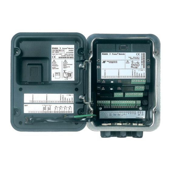
Terminal Plate OXY 3400-067 Module Attaching the terminal plates The terminal plates of the lower modules can be sticked to the inner side of the door. This facilitates maintenance and service. -
Page 16: Installing The Module
Installing the Module CAUTION! Electrostatic discharge (ESD). The modules' signal inputs are sensitive to electrostatic discharge. Take measures to protect against ESD before inserting the module and wiring the inputs. Note: Strip the insulation from the wires using a suitable tool to prevent dam- age. -
Page 17: Wiring
Wiring OXY 3400(X)-067 Traces 001 1) ISM 2) Sensor type Standard Traces 01 SE 7*6 ... SE 7*7 ... VP6-ST cable VP6-ST cable cathode Coax core Coax core Coax core transparent transparent transparent anode Coax shield Coax shield Coax shield reference n.c. -
Page 19: Calibration / Adjustment
Calibration / Adjustment Note: Function check (HOLD) active for the currently calibrated module Current outputs and relay contacts behave as configured • Calibration: Detecting deviations without readjustment • Adjustment: Detecting deviations with readjustment NOTICE! Without adjustment every dissolved oxygen meter delivers an imprecise or wrong output value! After replacing the sensor, the electrolyte, or the sensor membrane, you must perform a calibration. - Page 20 Calibration / Adjustment Adjustment Adjustment means that the values determined by a calibration are taken over. The values determined for zero and slope are entered in the calibration record. (Cal record can be opened in the Diagnostics menu for the module). These values are only effective for calculating the measured variables when the cali- bration has been terminated with an adjustment.
-
Page 21: Recommendations For Calibration
Calibration / Adjustment Recommendations for Calibration It is always recommended to calibrate in air. Compared to water, air is a calibra- tion medium which is easy to handle, stable, and thus safe. In the most cases, however, the sensor must be dismounted for a calibration in air. In certain pro- cesses the sensor cannot be removed for calibration. -
Page 22: Hold Function During Calibration
HOLD Function During Calibration Behavior of the signal and relay outputs during calibration Measuring Calibration K2 contact Module A Selecting the "HOLD" is Module B measuring module active The current output of Module A Module B the selected Calibration Calibration module is in function check (HOLD) - Page 23 Menu Display Selecting a calibration method Open calibration 83.0%Air 25.6 °C Press menu key to select menu. Menu selection Select calibration using arrow keys, press enter to confirm, passcode 1147 (To change passcode, select: Parameter setting / System control / Select: [enter] Passcode entry).
-
Page 24: Automatic Calibration In Water
Calibration / Adjustment Automatic Calibration in Water Automatic Calibration in Water The slope is corrected using the saturation value (100 %) related to air saturation. During calibration the module is in function check (HOLD) mode. Current outputs and relay contacts of the module behave as configured (BASE module). - Page 25 Menu Display Automatic calibration in water Display of selected calibration 80.3%Air 25.6 °C medium (Air-sat. water) Automatic - Water Enter cal pressure if “manual” has been Cal medium: Air-sat. water When changing sensors perform configured. First cal for statistics! Start by pressing softkey or enter Sensor replacement 1013 mbar Input cal pressure...
-
Page 26: Automatic Calibration In Air
Calibration / Adjustment Automatic Calibration in Air Automatic Calibration in Air The slope is corrected using the saturation value (100 %), similar to air satu- ration of water. Since this analogy only applies to water-vapor saturated air (100 % relative humidity) and often the calibration air is less humid, the relative humidity of the calibration air must also be specified. - Page 27 Menu Display Automatic calibration in air 80.3%Air Cal medium: Air 25.6 °C Automatic - Air Select: First calibration Cal medium: Air-sat. water Enter relative humidity, e.g.: When changing sensors perform First cal for statistics! • Ambient air: 50 % Sensor replacement Relative humidity •...
-
Page 28: Product Calibration (Calibration With Sampling)
Calibration / Adjustment Product Calibration (saturation, concentration, partial pressure [hPa, mmHg] Preset in: Parameter setting / Cal preset values) Product Calibration (Calibration with Sampling) When the sensor cannot be removed – e.g. for sterility reasons – its slope can be determined with “sampling”. To do so, the currently measured saturation value of the process is stored by the Protos. - Page 29 Menu Display Product calibration: Saturation 80.3%Air Product calibration Sat 25.6 °C Product calibration is performed in Product calibration Sat Cal medium: Product 2 steps. Cal by taking sample Prepare reference measurement and entering saturation (e.g. with portable meter): Start by pressing softkey or enter: Start Return 80.3%Air...
-
Page 30: Data Entry Of Premeasured Sensors
Calibration / Adjustment Data Entry of Premeasured Sensors (not required for ISM sensors) Data Entry of Premeasured Sensors Entry of values for slope and zero point of a sensor, related to 25 °C/77 °F, 1013 mbar. During calibration the module is in function check (HOLD) mode. Current outputs and relay contacts of the module behave as configured (BASE module). -
Page 31: Zero Correction
Calibration / Adjustment Zero Correction Zero Correction The sensor models SE 7*6 ... and SE7*7 ... have a very low zero current. For trace measurements below 500 ppb, the zero point should be calibrated. If a zero correction is performed, the sensor should remain for at least 10 to 60 minutes in the calibration medium (media containing CO at least 120 min) to obtain stable, non-drifting values. -
Page 32: Temp Probe Adjustment
Calibration / Adjustment Temp Probe Adjustment Note: With Protos II 4400(X) in the Calibration menu, with Protos 3400(X) in the Maintenance menu. Temp Probe Adjustment This function allows compensating for the individual temperature probe tol- erance and the influence of the lead resistances to increase the accuracy of temperature measurement. -
Page 33: Parameter Setting
Parameter Setting CAUTION! Incorrect parameter setting, calibration or adjustment may result in incorrect measurements being recorded. Protos must therefore be commissioned by a system specialist, all its parameters must be set, and it must be fully adjusted. NOTICE! The "function check” (HOLD) mode is active during parameter setting. The behavior of the current outputs depends on the parameter setting, i.e., they may be frozen at the last measurement or set to a fixed value. -
Page 34: Parameter Setting: Operating Levels
Parameter Setting: Operating Levels Viewing level, Operator level, Administrator level Note: Function check (HOLD) mode active (Setting: BASE module) Viewing level, Operator level, Menu Display Administrator level 82.3% Air Open parameter setting 25.6 °C From the measuring mode: Menu selection Press menu key to select menu. -
Page 35: Parameter Setting: Locking A Function
Parameter Setting: Locking a Function Administrator level: Enabling/locking functions for Operator level Note: Function check (HOLD) mode active (Setting: BASE module) Administrator level: Menu Display Enabling / locking functions Example: Blocking access to the calibration adjustments from the Operator level 82.3% Air Open parameter setting 25.0°C... -
Page 36: Activating Parameter Setting
Activating Parameter Setting Menu Display Parameter setting Opening the parameter setting 82.3% Air 25.0°C menu Menu selection From the measuring mode: Press menu key to select menu. Select parameter setting using arrow Select: [enter] keys, press enter to confirm. Return to meas Lingua Passcode as delivered: 1989 82.3% Air... - Page 37 Setting the Sensor Data Parameters Sensor data: Sensor monitoring details Note: Function check (HOLD) mode active Menu Display Display Parameter selection 100.4%Air Sensor data (see following page) 20.1 °C Sensor data are preset depending on Module OXY 3400-067 (Administrator) Input filter the sensor type.
- Page 38 Parameter Default Selection / Range Input filter Pulse suppression Weak Off, Weak, Medium, Strong Input filter 010 sec xxx sec (entry) Sensor data Measure in Liquids Liquids, Gases Sensor type Trace sensor 01 Standard sensor (SE 7*6 ...), Trace sensor 01 (SE 7*7 ...), Trace sensor 001 , Other or defined by ISM...
- Page 39 Parameter Default Selection / Range Sensor monitoring details (continued) Auto: Other Nominal: -0100 nA (with ISM sensor: Default slope) Min.: -0900 nA (with ISM: Min. range) Max.: -0030 nA (with ISM: Max. range) Individual: permisible range 25 ... 9999 nA Slope message Maint.
- Page 40 Parameter Default Selection / Range Sensocheck Auto Auto, Individual Monitoring of nominal impedance; determined by calibration, taken over by adjustment. Individual allows specifying the values: Nominal: xxxx kΩ Min.: xxxx kΩ Max.: xxxx kΩ Sensocheck message Maint. request Off, failure, maintenance request Response time Auto Auto, Individual...
- Page 41 Parameter Default Selection / Range Cal preset values Product calibration %Air SAt (%Air), Conc (mg/l, µg/l, ppm, ppb), p´ (mmHg, mbar) Calibration timer - Monitoring Auto Off, Auto, Individual - Cal timer 0000 h With ISM: Off, Without ISM: Entry (xxxx h) Pressure correction Pressure transmitter Difference...
-
Page 42: Sensoface
Sensoface Sensoface is a graphic indication of the sensor condition. The “smileys” provide information on wear and required maintenance of the sensor (“friendly” - “neutral” - “sad”). 10.3 mA 02/05/17 Sensoface Criteria (adjustable – see Sensor monitoring) Parameter Critical range Standard sensor Trace sensor 01 Trace sensor 001... -
Page 43: Calculation Blocks
Calculation Blocks Select menu: Parameter setting/System control/Calculation Blocks Calculation of new variables from measured variables Calculation Blocks Two measuring modules with all their measured values serve as input for the calculation block. In addition, the general device status (NAMUR signals) is taken into account. - Page 44 Activating a Calculation Block Select menu: Parameter setting/System control/Calculation Blocks Combining Measuring Modules With three measuring modules the following Calculation Block combinations are possible: Up to two Calculation Blocks can be activated. All current outputs can be set to output the new process variables formed by the Calculation Blocks.
-
Page 45: Logbook
Parameter Setting Parameter setting/System control Note: Function check (HOLD) mode active Menu Display Logbook, Factory setting 83.4%Air Logbook 25.6 °C Select which messages are to be Logbook (Administrator) recorded in the logbook. Log failure Log warning The logbook directly displays the Erase logbook last events with date and time, e.g. -
Page 46: Messages: Default Settings And Selection Range
Parameter Setting Messages: Default settings and selection range Note: Function check (HOLD) mode active Parameter Default Selection / Range Messages Gas Off, variable limits* • Concentration Off, variable limits* • Partial pressure Off, device limits max., variable limits* • Air pressure Messages Liquid Off, variable limits* •... - Page 47 Setting the Message Parameters Messages Note: Function check (HOLD) mode active Menu Display Messages Messages 83.4%Air 20.1 °C All parameters determined by the Messages (Administrator) measuring module can generate Messages Saturation %Air Messages Saturation %O 2 messages. Messages Concentration • Device limits max: Messages Partial pressure Message Air pressure Messages are generated when the...
-
Page 48: Configuring A Current Output
Current Outputs Select menu: Parameter setting/Module BASE Note: Function check (HOLD) mode active Parameter setting Menu Display BASE module 85%Air Configuring a Current Output 19.2°C • Open parameter setting Module BASE (Administrator) • Enter passcode Output current I2 Contact K4 (NAMUR Failure) •... -
Page 49: Current Outputs: Characteristics
Current Outputs: Characteristics Select menu: Parameter setting/Module BASE Note: Function check (HOLD) mode active • Linear characteristic The process variable is represented by a linear output current curve. Output current Process variable Start • Trilinear characteristic Two additional vertices must be entered: Output current 2nd vertex Y 1st vertex Y... - Page 50 • Function characteristic Nonlinear output current characteristic: allows measurements over several decades, e.g. measuring very low values with a high resolution and high values with a low resolution. Required: Entering a value for 50 % output current. Output current Entry for “50 % point”: e.g.: 10 % of measured value Process variable...
-
Page 51: Current Outputs: Output Filter
Current Outputs: Output Filter Select menu: Parameter setting/Module BASE/Output current I.../Output filter Note: Function check (HOLD) mode active Time averaging filter To smoothen the current output, a low-pass filter with adjustable time interval can be switched on. When there is a jump at the input (100 %), the output level is at 63 % after the time interval has been reached. -
Page 53: Maintenance
Maintenance Sensor monitor, temp probe adjustment Note: Function check (HOLD) mode active Menu Display Maintenance Opening the Maintenance menu 80.7%Air 25.6°C From the measuring mode: Menu selection Press menu key to select menu. Select maintenance using arrow keys, confirm with enter. Select: [enter] Passcode 2958 (To change passcode:... -
Page 54: Diagnostic Functions
Diagnostic Functions General status information of the measuring system Menu selection: Diagnostics Menu Display Diagnostic functions Opening the diagnostics menu 83.1 % Air 23.7 °C From the measuring mode: Menu selection Press menu key to select menu. Select diagnostics using arrow keys, confirm by pressing enter. -
Page 55: Device Description
Menu Display Diagnostics functions Device description 83.1 % Air 22.7 °C Select module using arrow keys: Device description Module OXY 3400-067 Provides information about all Input for O2 and °C modules installed: Function, serial Hardware: 1, Software: 3.1 Serial number 0002483 number, hardware and software Module FRONT... -
Page 56: Module Diagnostics
Diagnostic Functions Menu selection: Diagnostics / Module OXY ... Menu Display Module diagnostics, Sensor monitor 3.4 %O 2 Open the diagnostics menu 23.0 °C From the measuring mode: Menu selection Press menu key to select menu. Select diagnostics using arrow keys, confirm by pressing enter. -
Page 57: Cal Record
Menu Display Cal record, Sensor diagram, Statistics Cal record 3.4 %O 2 23.0 °C Data of last calibration, suitable for Cal record Last calibration 07/01/10 10:29 documentation to ISO 9000 and GLP Automatic - Water Cal mode (Date, time, calibration method, sensor zero and Zero +0.010 nA slope, rel. -
Page 58: Setting Diagnostic Messages As Favorite
Setting Diagnostic Messages as Favorite Select menu: Parameter setting/System control/Function control matrix Secondary Displays (1) Here, additional values are displayed in the measuring mode according to the factory setting. When the respective softkey (2) is pressed, the process variables measured by the modules plus date or time are displayed. - Page 59 Menu Display Select favorites Favorites menu Diagnostics functions can be called directly from the measuring mode using a softkey. The “Favorites” are selected in the Diagnostics menu. Favorites menu 09/03/14 83.3%Air Select favorites 25.6 °C Press menu key to select menu. Menu selection Select diagnostics using arrow keys, confirm with enter.
-
Page 60: Message List
Diagnostic Functions General status information of the measuring system Select menu: Diagnostics - Message list Menu Display Diagnostic functions Opening the diagnostics menu 82.3 %Air 25.6°C From the measuring mode: Menu selection Press menu key to select menu. Select diagnostics using arrow keys, confirm by pressing enter. - Page 61 Messages Messages for OXY 3400(X)-067 Module with Protos 3400(X) OXY messages Message type D008 Meas. processing (factory settings) FAIL D009 Module failure (Firmware Flash check sum) FAIL D010 Saturation %Air Range FAIL D011 Saturation %Air Alarm LO_LO FAIL D012 Saturation %Air Alarm LO WARN D013 Saturation %Air Alarm HI...
- Page 62 Messages OXY messages Message type D041 Air pressure Alarm LO_LO FAIL D042 Air pressure Alarm LO WARN D043 Air pressure Alarm HI WARN D044 Air pressure Alarm HI_HI FAIL D045 Saturation %O2 Range FAIL D046 Saturation %O2 Alarm LO_LO FAIL D047 Saturation %O2 Alarm LO WARN...
- Page 63 Messages OXY messages Message type D113 Sensor operating time (duration of use) User-defined D114 Membrane body changes User-defined D115 Inner body changes User-defined D120 Wrong ISM sensor FAIL D121 ISM sensor (error in factory settings/characteristics) FAIL D122 ISM sensor memory (error in cal data records) WARN D123 New sensor, adjustment required...
- Page 64 Messages Calculation Block OXY/OXY Messages Message type H022 Concentration-Diff Alarm LO WARN H023 Concentration-Diff Alarm HI WARN H024 Concentration-Diff Alarm HI_HI FAIL H045 %O2-Diff Range FAIL H046 %O2-Diff Alarm LO_LO FAIL H047 %O2-Diff Alarm LO WARN H048 %O2-Diff Alarm HI WARN H049 %O2-Diff Alarm HI_HI...
- Page 65 Messages Messages for OXY 3400(X)-067 Module with Protos II 4400(X) Failure Out of Specification Maintenance Required Message Type OXY Messages D008 Failure Meas. Processing (Factory Settings) D009 Failure Firmware Error D010 Failure Saturation %air range D011 Failure Saturation %Air Alarm LO_LO D012 Out of Specification Saturation %Air Alarm LO...
- Page 66 Messages Message Type OXY Messages Failure/ D060 Sad Sensoface: Slope Maintenance Required Failure/ D061 Sad Sensoface: Zero Point Maintenance Required D062 User-defined Sad Sensoface: Sensocheck D063 Maintenance Required Sad Sensoface: Response Time D064 Maintenance Required Sad Sensoface: Calibration timer D070 User-defined Sad Sensoface: Sensor Wear D080...
- Page 67 Messages Message Type Calculation Block OXY / OXY Messages H010 Failure Saturation %AIR Diff Range H011 Failure Saturation %AIR Diff Alarm LO_LO H012 Out of Specification Saturation %AIR Diff Alarm LO H013 Out of Specification Saturation %AIR Diff Alarm HI H014 Failure Saturation %AIR Diff Alarm HI_HI...
-
Page 69: Specifications
Specifications Protos OXY 3400(X)-067 Specifications Input for sensors SE 7*6 ... , SE 7*7 ... or "other" Automatic range selection: Input range 1 Meas. current 0 ... 600 nA, resolution 10 pA Meas. error < 0.5 % meas. val. + 0.05 nA + 0.005 nA/K Input range 2 Meas. - Page 70 Specifications Intelligent Sensor Management Display of sensor data: Manufacturer, serial number, calibration record, load matrix a.o. Sensor monitoring Sensocheck Monitoring of membrane and electrolyte Sensoface provides information on the sensor condition: Sensor diagram Zero, slope, response time, calibration interval, Sensocheck, wear (ISM) Sensor monitor Direct display of measured values from sensor for validation: Sensor current / barometric pressure / temperature / I input...
- Page 71 Specifications General data Explosion protection See certificates or www.knick.de (Ex version of module only) RoHS conformity According to EU directive 2011/65/EU EN 61326-1, EN 61326-2-3 NAMUR NE 21 Emitted interference Industrial applications* (EN 55011 Group 1 Class A) Interference immunity...
-
Page 72: Appendix
Appendix: Minimum Spans for Current Outputs The OXY 3400(X)-067 module is a measuring module. It does not provide cur- rent outputs. Current outputs are provided by the BASE module (basic device) or by communication modules (e.g. OUT, PID). The corresponding parameters must be set there. -
Page 73: Dissolved Oxygen Measurement In Carbonated Beverages (Only With Protos 3400(X): Sw3400-011)
Dissolved Oxygen Measurement in Carbonated Beverages (Only with Protos 3400(X): SW3400-011) Application-specific add-on function for breweries Recommended only for SE 7*7 ... series sensors! This add-on function simplifies parameter setting since all steps not required for dissolved oxygen measurement in carbonated beverages are omitted. It simultaneously acts on all installed OXY modules (module firmware version 2.2 and higher). -
Page 74: Overview
Overview Overview of Parameter Setting Parameter Setting Menu Parameter Setting 7.00 pH 25.6 °C From measuring mode: Press menu key to select menu. Menu selection Select parameter setting using arrow keys, press enter to confirm. Administrator level Select: [enter] Access to all functions, also passcode setting. Releasing or Return to meas Lingua blocking functions for access from the Operator level. - Page 75 Overview Overview of Parameter Setting Parameter Setting Menu FRONT Module: Display Settings Language Select the menu language Units Select the measurement units Formats Select the display format Measurement display Representation of measured values on the display Display Brightness/contrast, auto-off BASE Module: Signal Outputs and Inputs, Contacts Output current I1, I2 Separately adjustable current outputs Contact K4...
- Page 76 Parameter Setting Menu OXY 3400-067 Module Input filter Sensor data Representation of measured values on the display: • Measure in Liquids, Gases • Sensor type Standard sensor, Trace sensor 01, Trace sensor 001, Other • Monitor sensor type Monitor, Off (for ISM sensor only) •...
- Page 77 Maintenance Menu BASE Module Current source Output current definable 0 ... 22 mA OXY 3400(X)-067 Module Sensor monitor Sensor current, air pressure, ext. pressure transmitter, RTD, temperature, impedance, current input Temp probe adjustment Compensating for lead length (with Protos 3400(X)) Autoclaving counter Shows the number of executed autoclaving cycles as well as the maximally permitted number of cycles...
-
Page 78: Index
Index Adjusting the temperature probe (Protos 3400) 53 Adjusting the temperature probe (Protos II 4400) 32 Adjustment 20 Administrator level 34 Application in hazardous locations 6 Attaching the terminal plates 15 Autoclaving counter (ISM only) 12 Automatic calibration in air 26 Automatic calibration in water 24 Behavior during messages 51 Bilinear characteristic 49... - Page 79 Index Data entry of premeasured sensors 30 Device description, Diagnostics menu 55 Device firmware 7 Device limits max. 47 Diagnostic functions 54 Diagnostic messages 61 Diagnostic messages as favorite 58 Disposal 2 Dissolved oxygen measurement in carbonated beverages (SW3400-011) 73 Electrostatic discharge (ESD) 16 EMC 71 Error messages 61...
- Page 80 Index ISM parameter setting 11 ISM plug and measure 9 ISM predictive maintenance 12 ISM, wiring 17 Linear characteristic 49 Lock icon 35 Locking a function 35 Logarithmic output curve 50 Logbook (Diagnostics menu) 54 Logbook (parameter setting) 45 Maintenance menu 53 Measuring point description 54 Membrane body changes (ISM only) 12 Message icons 47...
- Page 81 Index Parameter setting 33, 36 Parameter setting, overview 74 Point of meas description 54 Rated operating conditions 71 Release (softkey function) 35 Restore factory setting 45 Restore factory settings 45 Returns 2 Safety Instructions 6 Screw clamp connector 71 Secondary displays 58 Sensocheck 42 Sensoface 37 Sensoface criteria 42...
- Page 82 Index Table of contents 3 Technical data 69 Temp probe adjustment (Protos 3400) 53 Temp probe adjustment (Protos II 4400) 32 Terminal plate 15 Traces 01/001, sensor type, wiring 17 Trademarks 2 Trilinear characteristic 49 Variable limits 47 Viewing level 34 Wiring 17 Zero correction 31...
- Page 83 Index...
- Page 84 Knick Elektronische Messgeräte GmbH & Co. KG Headquarters Beuckestraße 22 • 14163 Berlin Germany Phone: +49 30 80191-0 Fax: +49 30 80191-200 info@knick.de www.knick.de Local Contacts www.knick-international.com Copyright 2019 • Subject to change Version: 7 This document was published on September 30, 2019.
Need help?
Do you have a question about the Protos OXY 3400-067 and is the answer not in the manual?
Questions and answers