Table of Contents
Advertisement
Quick Links
Betriebsanleitung
Betriebsanleitung
User Manual
Aktuelle Produktinformation: www.knick.de
Aktuelle Produktinformation: www.knick.de
Latest Product Information: www.knick.de
Analysenmesssystem
Analysenmesssystem
Protos 3400(X)
Protos 3400(X)
Protos 3400(X)
Process Analysis System
Messmodul Protos CONDI 3400 (X)-051
Messmodul Protos CONDI 3400 (X)-051
Protos LDO 3400-170 Measuring Module
Deutsch
Deutsch
English
zur Leitfähigkeitsmessung mit induktiven Sensoren
zur Leitfähigkeitsmessung mit induktiven Sensoren
For Optical Oxygen Measurement
in Liquids and Gases
The Art of Measuring.
The Art of Measuring.
Advertisement
Chapters
Table of Contents

Related Manuals for Knick Protos LDO 3400-170


Summary of Contents for Knick Protos LDO 3400-170
- Page 1 Protos 3400(X) Process Analysis System Betriebsanleitung Betriebsanleitung Messmodul Protos CONDI 3400 (X)-051 Messmodul Protos CONDI 3400 (X)-051 User Manual Protos LDO 3400-170 Measuring Module Deutsch Deutsch English zur Leitfähigkeitsmessung mit induktiven Sensoren zur Leitfähigkeitsmessung mit induktiven Sensoren For Optical Oxygen Measurement in Liquids and Gases Aktuelle Produktinformation: www.knick.de...
-
Page 2: Return Of Products Under Warranty
The following trademarks are used in this manual without further marking: CalCheck®, Calimatic®, Protos®, Sensocheck®, Sensoface®, ServiceScope®, Unical®, VariPower®, Ceramat®, SensoGate® are registered trademarks of Knick Elektronische Messgeräte GmbH & Co. KG, Germany Memosens® is a registered trademark of Endress+Hauser Conducta GmbH & Co. KG, Germany Knick Elektronische Messgeräte GmbH &... -
Page 3: Table Of Contents
Table of Contents Protos LDO 3400-170 Module Return of Products under Warranty ..................2 Disposal ............................2 Trademarks ........................... 2 Intended Use ....................6 Conformity with FDA 21 CFR Part 11 .................. 6 Safety Information ..................7 Software Version ......................... 8 Modular Concept ........................ - Page 4 Table of Contents Protos LDO 3400-170 Module Parameter Setting: Locking a Function ................34 Activating Parameter Setting ....................35 Documenting Parameter Setting ..................36 ProgaLog 3000 Software (Option) for Configuration and Documentation ..38 Configuration using "ProgaLog 3000" ..............41 Setting the Sensor Data Parameters............42 Sensoface ............................47...
- Page 5 Table of Contents Protos LDO 3400-170 Module Sensor Network Diagram ......................69 CIP/SIP Cycles, Autoclaving Counter .................70 Setting Diagnostics Messages as Favorite ..............71 Message List ..........................73 Specifications ....................78 Appendix: ....................... 81 Minimum Spans for Current Outputs ................81 Index ....................... 86...
-
Page 6: Intended Use
Intended Use The module is used to measure oxygen in liquids and gases using an optical sensor of the SE 740 series. The module permits simultaneous measurement of oxygen partial pressure, barometric pressure and temperature. In addition, oxygen saturation or concentration and volume concentration in gases can be calculated and displayed. -
Page 7: Safety Information
Safety Information NOTICE! Never try to open the module! If a repair should be required, return the module to our factory. If the specifications in the instruction manual are not sufficient for assessing the safety of operation, please contact the manufacturer to make sure that your intended application is possible and safe. -
Page 8: Software Version
Software Version LDO 3400-170 Module Protos 3400 Device Software The LDO 3400-170 module is supported by software version A.0 or higher. LDO 3400-170 Module Software Software version 1.x Querying the Device/Module Software Version When the analyzer is in measuring mode: Press menu key, open Diagnostics menu: Device description Menu Display Device description... -
Page 9: Modular Concept
• FIU (radio, Memosens, Unical) (software occupies 2 slots) • Unical probe controller Documentation The basic unit is accompanied by a CD-ROM containing the complete documentation. Latest product information as well as user manuals for earlier software releases are available at www.knick.de. -
Page 10: Short Description
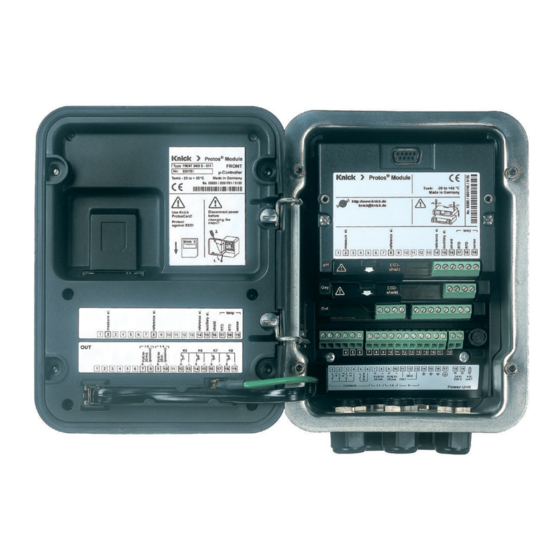
Short Description Short Description: FRONT Module 4 captive screws Transflective LC graphic display for opening the analyzer (240 x 160 pixels) (NOTICE! Make sure that the gasket between FRONT and white backlighting, high resolution BASE is properly seated and clean!) and high contrast. -
Page 11: Short Description: Menu Structure
Short Description: Menu Structure Basic Functions: Calibration, Maintenance, Parameter Setting, Diagnostics Menu groups Maintenance Parameter setting Diagnostics Calibration Measure Passcode: 1246 1147 2958 Operator level 1989 Administrator level Selecting BASE SYSTEM Message list Module 1 Point of meas Module 1 further FRONT Module 2... - Page 12 Short Description: FRONT Module View into the open device (FRONT module) Slot for Protos card • Data recording The Protos card expands the measure- ment recorder capacity to > 50000 records. • Exchange of parameter sets 5 parameter sets can be stored on the Protos card, 2 of them can be load- ed to the analyzer and switched by remote control.
-
Page 13: Short Description: Base Module
Short Description: BASE Module View into the open device (BASE module, 3 function modules installed) Module equipment Module identification: Plug & Play. Up to 3 modules can be combined as desired. Several input and communication modules are available. Please note: Protos 3400 allows operating only one optical oxygen sensor at the same time. -
Page 14: Terminal Plate
Terminal Plate of LDO 3400-170 Module: ® Protos Module Type LDO 3400-170 -20 to +55 °C Made in Germany http://www.knick.de knick@knick.de Input Input 0(4) to 20 mA 10 11 12 13 14 15 16 17 18 19 Attaching the Terminal Plates The terminal plates of the lower modules can be sticked to the inner side of the door. -
Page 15: Inserting The Module
Inserting the Module Make sure that the cable glands are tightly closed to protect against humidity. Switch off power supply. Open the device (loosen the 4 screws at the front). Place module in slot (D-SUB connector). Tighten fastening screws of the module. Connect sensor cable and control cable. -
Page 17: Wiring
Wiring Cable, e.g. CA/M12-005N485 Color Assignment Terminal number Cable strand LDO 3400-170 module White Brown Pink Gray Black The signal from an external pressure transmitter can be fed in through the external current input (terminals 8 and 10, see terminal plate on page 14). This allows pressure correction of the oxygen measurement. -
Page 18: Menu Selection
Menu Selection After switching on, the analyzer performs an internal test routine and automatically detects the number and type of modules installed. Then, the analyzer goes to measuring mode. 82.3 %Air 25.1 °C Menu selection %Air °C 24.0°C 25.8°C Select: [enter] Return to meas Lingua... -
Page 19: Passcode Entry
Passcode Entry Entering a passcode Select the position using the left/right keys, then edit the number using the up/down keys. When all numbers have been entered, confirm by pressing enter. Changing a passcode • Open the menu selection (menu) • Select parameter setting •... -
Page 20: Configuring The Measurement Display
Configuring the Measurement Display Select menu: Parameter setting/Module FRONT/Measurement display Pressing meas (1) returns the analyzer to the measuring mode from any function. All process variables coming from the modules can be displayed. The table on the next page describes how to configure the measurement display. - Page 21 Configuring the Menu Display measurement display Configuring the measurement 82.3 %Air 25.6°C display Menu selection Press menu key to select menu. Select parameter setting using arrow keys, press enter to confirm. Select: “Administrator level”: Passcode 1989 Select: [enter] (default setting). Lingua Return to meas 82.3 %Air...
-
Page 22: Calibration / Adjustment
Calibration and adjustment Calibration / Adjustment Note: HOLD mode (Setting: BASE module) Current outputs and relay contacts behave as configured Adjustment: The sensor adjusts itself. Adjustment is started and monitored via Protos. NOTICE: Without adjustment every oxygen meter delivers an imprecise or wrong output value! After replacing the sensor or the sensor membrane, you must perform an adjustment. -
Page 23: Recommendations For Calibration
Calibration / Adjustment Recommendations for Calibration It is always recommended to calibrate in air. Compared to water, air is a cal- ibration medium which is easy to handle, stable, and thus safe. In the most cases, however, the sensor must be removed for a calibration in air. In certain processes the sensor cannot be removed for calibration. -
Page 24: Hold Function During Calibration
HOLD Function During Calibration Behavior of the signal and relay outputs during calibration Measuring Calibration K2 contact Module A "HOLD" is Selecting the measuring module Module B active (not with 2 optical oxygen sensors) The current output of Module A Module B the selected Calibration... - Page 25 Menu Display Selecting a calibration method Opening the Calibration Menu 83.0%Air 25.6°C Press menu key to select menu. Menu selection Select calibration using arrow keys, press enter to confirm, passcode 1147 (To change passcode, select: Parameter setting / System control / Select: [enter] Passcode entry)
-
Page 26: Automatic Calibration In Water
Automatic calibration in water Calibration / Adjustment Automatic Calibration in Water Automatic Calibration in Water The slope is corrected using the saturation value (100 %) of water in equilib- rium with air. During calibration the module is in HOLD mode. Current outputs and relay contacts of the module behave as configured (BASE module). - Page 27 Automatic calibration Menu Display in water 80.3%Air Display of selected calibration 25.6°C medium (Air-sat. water) Automatic - Water Enter cal pressure if “manual” has been Cal medium: Air-sat. water configured. Input cal pressure 1013 mbar Start with softkey or enter Start Return 80.3%Air...
-
Page 28: Automatic Calibration In Air
Automatic calibration in air Calibration / Adjustment Automatic Calibration in Air Automatic Calibration in Air The slope is corrected using the saturation value (100 %), similar to air satu- ration of water. Since this analogy only applies to water-vapor saturated air (100 % relative humidity) and often the calibration air is less humid, the relative humidity of the calibration air must also be specified. - Page 29 Menu Display Automatic calibration in air 80.3%Air Calibration medium: Air 25.6°C Select: First calibration Automatic - Air Calibration medium: Air Enter relative humidity, e.g.: • Ambient air: 50 % 0050 % Relative humidity • Bottled gas: 0 % 1013 mbar Input cal pressure Enter cal pressure if “manual”...
-
Page 30: Product Calibration (Calibration With Sampling)
Product calibration: Saturation Calibration / Adjustment Product Calibration (saturation/concentration/partial pressure [hPa, mmHg]) Preset in: Parameter setting / Cal preset values Product Calibration (Calibration with Sampling) When the sensor cannot be removed – e.g. for sterility reasons – its slope can be determined with “sampling”. - Page 31 Menu Display Product calibration Product Calibration 80.3%Air 25.6°C Product calibration is performed in Product calibration Sat Cal medium: Product 2 steps. Cal by taking sample Prepare reference measurement and entering lab value (e.g. using a portable meter), start with softkey or enter. Return Start 80.3%Air...
-
Page 32: Zero Correction
Zero correction Calibration / Adjustment Zero Correction Zero Correction For trace measurements below 500 ppb, the zero point should be calibrated. If you want to perform a zero correction, then you should keep the sensor in the calibration medium (eg, N 2 or sulfite solution) until the measured value has stabilized. -
Page 33: Parameter Setting: Operating Levels
Parameter setting Parameter Setting: Operating Levels Viewing level, Operator level, Administrator level Note: HOLD mode (Setting: BASE module) Viewing level, Operator level, Menu Display Administrator level 82.3% Air Opening the Parameter Setting 25.6 °C Menu Menu selection From the measuring mode: Press menu key to select menu. -
Page 34: Parameter Setting: Locking A Function
Parameter Setting: Locking a Function Administrator level: Enabling / locking functions for Operator level Note: HOLD mode (Setting: BASE module) Administrator level: Menu Display Enabling / locking functions Example: Blocking calibration adjust- ments for the Operator level Open the parameter setting menu 82.3% Air Select Administrator level. -
Page 35: Activating Parameter Setting
Activating Parameter Setting Opening the parameter setting menu Menu Display Parameter setting Opening the Parameter Setting 82.3% Air 25.0°C Menu Menu selection From the measuring mode: Press menu key to select menu. Select parameter setting using arrow Select: [enter] keys, press enter to confirm. Return to meas Lingua Passcode as delivered: 1989... -
Page 36: Documenting Parameter Setting
Documenting Documenting Parameter Setting You must reproducibly document all parameter settings in the device to achieve a high level of system and device security according to GLP. For that purpose, an Excel file is provided (on the CD-ROM shipped with the basic device) to enter the parameter settings. - Page 37 Documenting Parameter Setting From the application window of the Excel file, select the worksheet for the module the parameter settings of which you want to document. Set the parameters of the respective module and enter the selected values in the corresponding cells of the module worksheet. NOTICE! The "HOLD"...
-
Page 38: Progalog 3000 Software (Option) For Configuration And Documentation
ProgaLog 3000 Software (Option) for Configuration and Documentation The ProgaLog 3000 software is available for convenient configuration of the Protos 3400(X) process analysis system. The user interface can be switched to the Protos display languages English, German, French, Spanish, Italian, Swedish or Portuguese. - Page 39 ProgaLog 3000 Software for Configuration and Documentation 4. Edit configuration data using ProgaLog 3000 When the configuration data have been loaded, the software lists the con- nected modules with all available configuration parameters: Fig.: ProgaLog 3000 configuration data The parameters are listed according to the modular device structure. All configuration parameters (except the "Sensor data details", which are deter- mined by digital sensors) can be edited at the PC.
- Page 40 ProgaLog 3000 Software for Configuration and Documentation Configuring the parameters, e.g. relay contact usage: Input errors are indicated by red highlighting: 5. Save the configuration data to Protos card 6. Load the configuration data to the 7.00 pH 25.6 °C Protos 3400 Copy configuration (Administrator) Parameter setting / System control /...
-
Page 41: Configuration Using "Progalog 3000
ProgaLog 3000 Software for Configuration and Documentation Configuration using "ProgaLog 3000" In the "Configurator" menu you can preconfigure a complete Protos 3400(X) process analysis system with up to 3 modules at your PC. 1. Select your configuration from the modular system components offered in the left-hand field. -
Page 42: Setting The Sensor Data Parameters
Setting the Sensor Data Parameters Opening the parameter setting menu Note: HOLD mode Menu Display Parameter setting Opening the Parameter Setting Menu 83.2 %Air 25.0°C From the measuring mode: Menu selection Press menu key to select menu. Select parameter setting using arrow keys, press enter to confirm. -
Page 43: Sensor Data
Sensor data Setting the Sensor Data Parameters Sensor data: Sensor monitoring details Note: HOLD mode Menu Display Display Parameter selection 100.4 %Air Sensor Data (see following page) 20.1 °C Sensor data are preset depending on Sensor SE 740 (Administrator) Input filter the sensor type. - Page 44 Parameter Choices (default in bold print) Input filter Pulse suppression Off, Weak, Medium, Strong xxx s (10 s) Input filter Sensor data Liquids, Gases Measure in On / Off Sensoface Sensor monitoring details (all messages: Off, Maint. request, Failure) Auto Slope Zero Auto...
- Page 45 Parameter Choices (default in bold print) Pressure correction Ext. pressure transmitter 0 ... 20 mA / 4 ... 20 mA I input Start 0(4) mA xxxx mbar (0000) End (20 mA) xxxx mbar (9999) Manual xxxx mbar / External Pressure during meas Manual xxxx mbar / External Pressure during cal Salinity correction...
-
Page 46: Sensoface
Sensoface Sensoface Sensoface is a graphic indication of the sensor condition. Prerequisite: Sensocheck must have been activated during parameter setting. Sensocheck: The error information is taken from the sensor. %Air °C 10.3 mA 05/02/14 The “smileys” provide information on wear and required maintenance of the sensor (“friendly”... -
Page 47: Logbook
Logbook Factory setting Logbook, Factory Setting Parameter setting/System control/Logbook Note: HOLD mode Menu Display Logbook, factory setting 83.1 % Air Logbook 25.6 °C Select which messages are to be Logbook (Administrator) logged in the logbook. Log failure Log warning The last 50 events are recorded with Erase logbook date and time. - Page 48 Setting the Message Parameters Messages Note: HOLD mode (Setting: BASE module) Menu Display Messages Messages 83.4 %Air 20.1 °C All parameters determined by the Messages (Administrator) measuring module can generate Messages Saturation %Air Messages Saturation %O 2 messages. Messages Concentration Messages Partial pressure Return 83.4 %Air...
-
Page 49: Configuring A Current Output
BASE module Current Outputs, Contacts, OK Inputs Select menu: Parameter setting/Module BASE Note: HOLD mode (Setting: BASE module) Parameter setting Menu Display BASE module 85 %Air Configuring a Current Output 19.2°C • Open parameter setting Module BASE (Administrator) • Enter passcode Output current I2 Contact K4 (NAMUR Failure) •... -
Page 50: Current Outputs: Characteristics
Current Outputs: Characteristics Select menu: Parameter setting/Module BASE • Linear characteristic The process variable is represented by a linear output current curve. Output current Process variable Start • Trilinear characteristic You must enter two additional vertices: Output current 2nd vertex Y 1st vertex Y Process variable Start... - Page 51 • Function characteristic Nonlinear output current characteristic: allows measurements over several decades, e.g. measuring very low values with a high resolution and high values with a low resolution. Required: Entering a value for 50 % output current. Output current Entry for “50 % point”: e.g.: 10 % of measured value Process variable...
-
Page 52: Output Filter
Output Filter Time interval Time Averaging Filter To smoothen the current output, a low-pass filter with adjustable time interval can be switched on. When there is a jump at the input (100 %), the output level is at 63 % after the time interval has been reached. The time interval can be set from 0 to 120 sec. -
Page 53: Namur Signals: Current Outputs
Current outputs: Behavior during messages NAMUR Signals: Current Outputs Behavior during messages: HOLD, 22 mA signal Behavior During Messages Depending on the configuration (“Messages”) 83.3 %Air 19.0°C the current outputs switch to: Behavior during messages • Currently measured value HOLD Current meas. -
Page 54: Namur Signals: Relay Contacts
NAMUR Signals: Relay Contacts Failure, Maintenance request, HOLD (function check) As delivered, the floating relay outputs of the BASE module are assigned to the NAMUR signals: Failure Contact K4, normally closed (signaling current failure) Maintenance request Contact K3, normally open contact HOLD Contact K2, normally open contact NAMUR signals: Factory setting of contacts... -
Page 55: Relay Contacts: Protective Wiring
Relay Contacts: Protective Wiring Protective Wiring of Relay Contacts Relay contacts are subject to electrical erosion. Especially with inductive and capacitive loads, the service life of the contacts will be reduced. For suppres- sion of sparks and arcing, components such as RC combinations, nonlinear resistors, series resistors, and diodes should be used. -
Page 56: Relay Contacts, Usage
Relay contacts Relay Contacts Parameter setting/Module BASE/Relay contacts Menu Display Setting the relay contacts 83.3 %Air Relay Contacts, Usage 19.2°C • Select parameter setting Contact K1 (Administrator) • Enter passcode: Usage NAMUR maintenance Variable NAMUR HOLD • Select “Module BASE” Limit value Limit value •... -
Page 57: Relay Contacts: Sensoface Messages
Relay Contacts: Sensoface Messages Parameter setting/Module BASE/Relay contacts/Usage/Sensoface Menu Display Parameter setting (Sensoface) 83.3 %Air Assigning Sensoface Messages to 19.0°C Relay Contacts Module BASE (Administrator) Output current I1 When more than one measuring Output current I2 module is used, the Sensoface mes- (NAMUR Failure) Contact K4 Contact K3... -
Page 58: Rinse Contact
Rinse contact Rinse Contact Parameter setting/Module BASE/Relay contacts/Usage/Rinse contact Menu Display Configuring the rinse contact 83.3 %Air Relay Contacts, Usage 19.2°C • Select parameter setting Contact K1 (Administrator) • Enter passcode: Usage NAMUR maintenance Variable NAMUR HOLD • Select “Module BASE” Limit value Limit value •... -
Page 59: Icons In The Measurement Display
Limit value Limit Value, Hysteresis, Contact Type Parameter setting/Module BASE/Relay contacts/Usage Menu Display Usage as limit value 83.3 %Air Relay Output: Limit value 19.2°C • Select parameter setting Contact K1 (Administrator) • Enter passcode: Usage NAMUR maintenance Variable NAMUR HOLD •... -
Page 60: Ok1,Ok2 Inputs: Specifying The Level
OK1,OK2 Inputs: Specifying the Level Parameter setting/Module BASE/Inputs OK1, OK2 Note: HOLD mode (Setting: BASE module) Menu Display Setting the OK inputs 83.3 %Air OK1 Usage 19.2°C • Select parameter setting Inputs OK1, OK2 (Administrator) • Enter passcode For OK2 usage see “Function control matrix”... -
Page 61: Switching Parameter Sets Via Ok2
Switching Parameter Sets via OK2 Parameter setting / System control / Function control matrix Note: HOLD mode (Setting: BASE module) Parameter sets 2 complete parameter sets (A, B) can be stored in the analyzer. You can switch between the parameter sets using the OK2 input. The currently activated set can be signaled by a relay contact. -
Page 62: Maintenance
Maintenance Maintenance Sensor monitor Note: HOLD mode (Setting: BASE module) Menu Display Maintenance Opening the Maintenance Menu 83.3 %Air 25.6°C From the measuring mode: Menu selection Press menu key to select menu. Select Maintenance (maint) using arrow keys, press enter to confirm. Select: [enter] Passcode 2958 (The passcode can be... -
Page 63: Diagnostics Functions
Diagnostics Logbook Diagnostics Functions General status information of the measuring system Select menu: Diagnostics Menu Display Diagnostics functions Opening the Diagnostics Menu 83.1 % Air 23.7 °C From the measuring mode: Menu selection Press menu key to select menu. Select diagnostics using arrow keys, confirm by pressing enter. -
Page 64: Device Description
Menu Display Diagnostics functions Device Description 83.1 % Air 22.7 °C Select module using arrow keys: Device description Module LDO 3400-170 Provides information on all modules Digital sensors installed: Function, serial number, Hardware: 1, Software: 1.0 Serial number: 004711 hardware and software version, and Module FRONT device options. -
Page 65: Sensor Monitor
Sensor monitor Module Diagnostics Sensor monitor / Cal record / Sensor network diagram / Sensor wear monitor Menu Display Sensor monitor 83.3 %Air Opening the Diagnostics Menu 23.0 °C From the measuring mode: Menu selection Press menu key to select menu. Select diagnostics using arrow keys, confirm by pressing enter. -
Page 66: Cal Record
Cal record Sensor network diagram Sensor wear monitor Cal record, Sensor network diagram, Menu Display Sensor wear monitor Cal Record 83.3 %Air 23.0 °C Data of last calibration, suitable for Cal record Active adjustment 06/09/14 15:30 documentation to ISO 9000 and GLP SE 740/1 Sensor model Serial No. -
Page 67: Cip/Sip Cycles, Autoclaving Counter
CIP/SIP Cycles, Autoclaving Counter CIP (Cleaning in Place) / SIP (Sterilization in Place) CIP/SIP cycles are used for cleaning or sterilizing the process-wetted parts in the process. They are performed for biotech applications, for example. Depending on the application, one (alkaline solution, water) or more chemicals (alkaline solution, water, acidic solution, water) are used. -
Page 68: Setting Diagnostics Messages As Favorite
Setting Diagnostics Messages as Favorite Select menu: Parameter setting / System control / Function control matrix Secondary Displays (1) Here, additional values are displayed in the measuring mode according to the factory setting. When the respective softkey (2) is pressed, the process variables measured by the modules plus date or time are displayed. - Page 69 Menu Display Selecting a favorite Favorites Menu Diagnostics functions can be called directly from the measuring mode %Air using a softkey. The “Favorites” are selected in the °C Diagnostics menu. Favorites menu 03/09/14 83.3 %Air Selecting a Favorite 25.6°C Press menu key to select menu. Menu selection Select Diagnostics using arrow keys, press enter to confirm.
-
Page 70: Message List
Message list Diagnostics Functions General status information of the measuring system Select menu: Diagnostics - Message list Menu Display Diagnostics functions Opening the Diagnostics Menu 82.3 %Air 25.6°C From the measuring mode: Menu selection Press menu key to select menu. Select diagnostics using arrow keys, press enter to confirm. - Page 71 Messages Module LDO 3400-170 OXY messages Message type D008 Meas. processing (factory settings) FAIL D009 Module failure (Firmware Flash check sum) FAIL D010 Saturation %Air Range FAIL D011 Saturation %Air Alarm LO_LO FAIL D012 Saturation %Air Alarm LO WARN D013 Saturation %Air Alarm HI WARN D014...
- Page 72 Messages OXY messages Message type D045 Saturation %O2 Range FAIL D046 Saturation %O2 Alarm LO_LO FAIL D047 Saturation %O2 Alarm LO WARN D048 Saturation %O2 Alarm HI WARN D049 Saturation %O2 Alarm HI_HI FAIL D060 Sad Sensoface: Slope WARN D061 Sad Sensoface: Zero WARN D062...
- Page 73 Messages OXY messages Message type D110 CIP counter User-defined D111 SIP counter User-defined D112 Autoclaving counter User-defined D113 Sensor operating time (duration of use) User-defined D130 SIP cycle counted Text D131 CIP cycle counted Text D200 Temp O2 conc/SAT WARN D201 Cal temp Text...
- Page 74 Messages Calculation Block OXY/OXY Messages Message type Concentration-Diff Alarm LO WARN Concentration-Diff Alarm HI WARN Concentration-Diff Alarm HI_HI FAIL %O2-Diff Range FAIL %O2-Diff Alarm LO_LO FAIL %O2-Diff Alarm LO WARN %O2-Diff Alarm HI WARN %O2-Diff Alarm HI_HI FAIL Vol%-Diff range (measurement in gases) WARN Vol%-Diff Alarm LO_LO (measurement in gases) FAIL...
-
Page 75: Specifications
Specifications Protos LDO 3400-170 Specifications Input for sensor Knick SE 740 • Display ranges "Standard": Saturation (-10 ... 80 °C) 0.0 ... 999.9 % Air 0.00 ... 99.99 % O Concentration (-10 ... 80 °C) 0.00 ... 99.99 mg/l (ppm) Volume concentration in gas 0.00 ... - Page 76 Specifications Sensor standardization Operating modes - Automatic calibration in air-saturated water - Automatic calibration in air - Product calibration: Saturation - Product calibration: Concentration and Product calibration: Partial pressure - Zero correction Calibration record Recording of: Zero, slope, calibration method with date and time of the last three calibrations and the first calibration Temperature input...
- Page 77 Specifications General Data NAMUR NE 21 and EN 61326-1 EN 61326-2-3 Emitted interference Class B (residential area) Immunity to interference Industry Lightning protection EN 61000-4-5, Installation Class 2 Nominal operating conditions Ambient temperature: -20 ... +55 °C Rel. humidity: 10 ... 95% not condensing Transport/Storage temperature -20 ...
-
Page 78: Appendix
Appendix: Minimum Spans for Current Outputs The LDO 3400-170 module is a measuring module. It does not provide current outputs. Current outputs are provided by the BASE module (basic device) or by communication modules (e.g. OUT, PID). The corresponding parameters must be set there. - Page 79 Overview of Parameter Setting Parameter Setting 83.3 %Air 25.6 °C Activated from measuring mode: Press menu key to select menu. Menu selection Select parameter setting using arrow keys, press enter to confirm. Administrator Level Select: [enter] Access to all functions, also passcode setting. Releasing or block- Lingua Return to meas ing functions for access from the Operator level.
- Page 80 Parameter Setting Menu Display Settings: FRONT Module Language Measured value display Representation of measured values on the display: • Main display - Select number of primary values displayed (one or two) • Display format - Decimal places • Viewing angle Measurement recorder Option: 2-channel, selection of process variable, start and end •...
- Page 81 Parameter Setting Menu LDO 3400-170 Module Input filter Sensor data Representation of measured values on the display: • Measure in Liquids, Gases • Sensoface • Details Slope, zero, temperature, Sensocheck, sensor wear, sensor operating time, CIP/SIP counter, O2 measurement with CIP/SIP, autoclaving counter Cal preset values •...
- Page 82 Maintenance Menu BASE Module Current source Output current definable 0 ... 22 mA LDO 3400-170 Module Sensor monitor Partial pressure, ext. pressure transmitter, temperature, current input Autoclaving counter Entry/Display of autoclaving cycles, display of maximally permit- ted number of cycles (when previously entered) Diagnostics Menu Message list List of all warning and failure messages...
-
Page 83: Index
Index Adjustment 22 Administrator level 33 Assigning measured values, start (4 mA) and end (20 mA) 51 Attaching the terminal plates 14 Audit Trail Log 6 Autoclaving counter, description 70 Autoclaving counter, maintenance 65 Automatic calibration in air 28 Automatic calibration in water 26 BASE module 13 Behavior during messages 55 Cable glands 10... - Page 84 Index Diagnostics messages 73 Diagnostics messages as favorite 71 Display icons 94 Disposal 2 Download area 39 Electronic signature 6 EMC 80 Error messages 74 Excel file for configuration 36 Factory setting 48 Failure 56 Favorites 71 FDA 21 CFR Part 11 6 FRONT module 12 Function check 56 Gasket 12...
- Page 85 Index Locking a function 34 Logarithmic output curve 53 Logbook, diagnostics 66 Logbook, parameter setting 48 Loss of passcode 19 Maintenance 65 Measurement display, configuring 20 Menu selection 18 Menu structure 11 Message icons 49 Message list 73 Messages 49 Messages, response of current outputs 55 Message when the current range is exceeded 55 Modular concept 9...
- Page 86 Index Parameter setting 35 Parameter setting, activating 35 Parameter setting, documentation 36, 37 Parameter setting, overview 82 Passcode entry 19 Phase angle, calibration 22 Product calibration 30 ProgaLog 3000 software 38 Protos card 12 Relay contacts, protective wiring 57 Relay contacts, Sensoface messages 59 Relay contacts, usage 58 Relay output, limit value 61 Release (softkey function) 34...
- Page 87 Index Serial number 8 Settings documentation 36 Short description 10 SIP (Sterilization in Place) 70 Slot for Protos card 12 Softkeys 10, 20 Software version 8 Specifications 78 Stern-Volmer constant, calibration 22 Stern-Volmer constant, permitted range 47 Symbols in display 94 Table of contents 3 Technical data 78 Terminal compartment 13...
- Page 88 Index...
- Page 89 Index...
- Page 90 Index...
- Page 91 Icon Explanation of icons important for this module The analyzer is in measuring mode. The analyzer is in calibration mode. HOLD mode active for the currently calibrated module. The analyzer is in maintenance mode. HOLD mode active. The analyzer is in parameter setting mode. HOLD mode active. The analyzer is in diagnostics mode.
- Page 92 LDO 3400-170 Menu Selection Calibration and adjustment ...........22 Automatic calibration in water ...............26 Automatic calibration in air ..............28 Product calibration: Saturation ...............30 Zero correction ....................32 Parameter setting ..............33 Documenting ....................36 Sensor data .....................43 Sensoface ......................47 Logbook ......................48 Factory setting ....................48 BASE module ....................51 Current outputs: Behavior during messages ........55 Relay contacts ....................58...
Need help?
Do you have a question about the Protos LDO 3400-170 and is the answer not in the manual?
Questions and answers