
Related Manuals for Rigol DSA700 Series


Summary of Contents for Rigol DSA700 Series
- Page 1 RIGOL User’s Guide DSA700 Series Spectrum Analyzer Mar. 2017 RIGOL TECHNOLOGIES, INC. 800.561.8187 information@itm.com www. .com...
-
Page 2: Safety Requirement
Use Proper Overvoltage Protection. Ensure that no overvoltage (such as that caused by a bolt of lightning) can reach the product. Otherwise, the operator might be exposed to the danger of an electric shock. User’s Guide for DSA700 Series 800.561.8187 information@itm.com www. - Page 3 Do Not Operate With Suspected Failures. If you suspect that any damage may occur to the instrument, have it inspected by RIGOL authorized personnel before further operations. Any maintenance, adjustment or replacement especially to circuits or accessories must be performed by RIGOL authorized personnel.
- Page 4 Do not expose the battery (if available) to high temperature or fire. Keep it out of the reach of children. Improper change of a battery (lithium battery) may cause an explosion. Use the RIGOL specified battery only. Handle with Caution.
-
Page 5: Safety Notices And Symbols
It calls attention to an operation, if not correctly performed, could result in damage to the product or other devices connected to the product. Safety Symbols on the Product: Hazardous Safety Protective Chassis Test Warning Earth Ground Ground Voltage Terminal User’s Guide for DSA700 Series 800.561.8187 information@itm.com www. .com... -
Page 6: Care And Cleaning
To avoid damage to the instrument, do not expose it to caustic liquids. WARNING To avoid short-circuit resulting from moisture or personal injuries, ensure that the instrument is completely dry before connecting it to the power supply. User’s Guide for DSA700 Series 800.561.8187 information@itm.com www. .com... -
Page 7: Environmental Considerations
Please contact your local authorities for disposal or recycling information. User’s Guide for DSA700 Series 800.561.8187 information@itm.com www. - Page 8 RIGOL User’s Guide for DSA700 Series 800.561.8187 information@itm.com www. .com...
-
Page 9: Dsa700 Series Overview
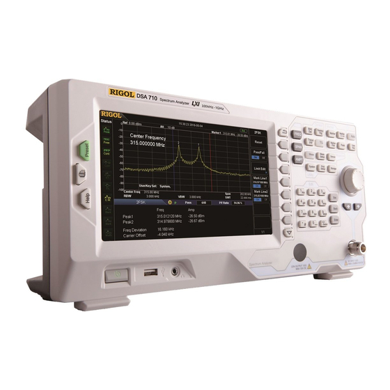
RIGOL DSA700 Series Overview DSA700 series spectrum analyzers which are small, light and cost-effective, are portable spectrum analyzers designed for starters. Configured with easy-to-operate numeric keyboard, high-resolution color LCD display and various remote communication interfaces, they can be widely used in various fields, such as education, company research and development as well as industrial manufacture. -
Page 10: Document Overview
This chapter lists the specifications and general specifications of the analyzer. Chapter 6 Appendix This chapter lists the options and accessories that can be ordered along with your analyzer as well as the service and support information. User’s Guide for DSA700 Series 800.561.8187 information@itm.com www. - Page 11 Freq indicates pressing FREQ at the front panel and then pressing the menu softkey Center Freq. Content conventions in this manual: The DSA700 series spectrum analyzer includes the following two models. The illustrations in this manual are based on DSA710. Model...
-
Page 12: Table Of Contents
Safety Notices and Symbols ..............V Allgemeine Sicherheits Informationen ............VI Sicherheits Begriffe und Symbole .............. IX Care and Cleaning ..................X Environmental Considerations ..............XI DSA700 Series Overview ..............XIII Document Overview ................XIV Chapter 1 Quick Start ................ 1-1 General Inspection ................. 1-2 Appearance and Dimensions .............. - Page 13 Remote Control Overview ............... 3-2 Remote Control Method ................. 3-3 User-defined Programming .............. 3-3 To Use PC software ................. 3-6 Chapter 4 Troubleshooting&Message ..........4-1 Troubleshooting ..................4-2 Messages ..................... 4-4 XVII User’s Guide for DSA700 Series 800.561.8187 information@itm.com www. .com...
- Page 14 SSC-DSA (Option) ................5-7 Input /Output .................. 5-8 General Specifications ................5-9 Chapter 6 Appendix ................6-1 Appendix A: Ordering Infomation ............. 6-1 Appendix B: Warranty ................6-2 Index ......................1 User’s Guide for DSA700 Series XVIII 800.561.8187 information@itm.com www. .com...
-
Page 15: Chapter 1 Quick Start
Chapter 1 Quick Start This chapter guides users to quickly get familiar with the appearance, dimensions, front/ rear panel and the user interface, as well as announcements during first use of DSA700 series spectrum analyzer. Subjects in this chapter: General Inspection ... -
Page 16: General Inspection
The consigner or carrier shall be liable for the damage to the instrument resulting from shipment. RIGOL would not be responsible for free maintenance/rework or replacement of the instrument. 2. Inspect the instrument In case of any mechanical damage, missing parts, or failure in passing the electrical and mechanical tests, contact your RIGOL sales representative. -
Page 17: Appearance And Dimensions
Chapter 1 Quick Start RIGOL Appearance and Dimensions Figure 1-1 Front View Unit: mm Figure 1-2 Side View Unit: mm User’s Guide for DSA700 Series 800.561.8187 information@itm.com www. .com... -
Page 18: To Prepare For Use
Users can also fold the supporting legs when the instrument is not in use for easier storage or shipment. To unfold the supporting legs To fold the supporting legs Figure 1-3 To Adjust the Supporting Legs User’s Guide for DSA700 Series 800.561.8187 information@itm.com www. .com... -
Page 19: To Connect To Power
Figure 1-4 Power Cord Connection CAUTION Make sure that the instrument is properly grounded to avoid electric shock. User’s Guide for DSA700 Series 800.561.8187 information@itm.com www. .com... -
Page 20: Power-On Inspection
Press System Calibrate Cal Now and the instrument will perform self-calibration using the internal calibration source. To Set the System Language DSA700 series spectrum analyzer supports multiple system languages. You can press System Language to switch the system language. User’s Guide for DSA700 Series 800.561.8187... -
Page 21: Front Panel
Figure 1-5 Front Panel Table 1-1 Front Panel Description Description Description Earphone jack Menu softkeys/menu control keys USB Host Function key area Power switch Knob Help Direction keys Print Numeric Keyboard Preset RF input User’s Guide for DSA700 Series 800.561.8187 information@itm.com www. .com... -
Page 22: Front Panel Function Keys
Set the parameters related to trace. Trace/P/F Configure the Pass/Fail test. Meas Select and control the measurement function**. Meas Setup Set the parameters for the selected measurement function**. Demod Set the demodulation function. User’s Guide for DSA700 Series 800.561.8187 information@itm.com www. .com... - Page 23 Restore the system to factory settings or user-defined state. Print or save the current screen. Help Turn on the built-in help. Note: **This function is only applicable for DSA700 with the corresponding option. User’s Guide for DSA700 Series 800.561.8187 information@itm.com www. .com...
-
Page 24: Front Panel Key Backlight
The backlight of Meas turns on when any of the advanced measurements is enabled and stays on until all measurement functions are disabled. Note: **This function is only applicable to DSA700 installed with the corresponding option. User’s Guide for DSA700 Series 1-10 800.561.8187 information@itm.com www. -
Page 25: Front Panel Connectors
Demod Demod Setup. CAUTION For fear of damaging your hearing, please turn the volume down to zero and gradually turn the volume up after putting on the earphone. 1-11 User’s Guide for DSA700 Series 800.561.8187 information@itm.com www. .com... - Page 26 To avoid damage to the instrument, for the signal input from the RF input terminal, the DC voltage component and the maximum continuous power of the AC (RF) signal component can not exceed 50 V and +20 dBm respectively. User’s Guide for DSA700 Series 1-12 800.561.8187 information@itm.com www.
-
Page 27: To Use The Numeric Keyboard
: press this key to input 1 in number input and switch between uppercase and lowercase letter in English input. This key is invalid in Chinese input. 1-13 User’s Guide for DSA700 Series 800.561.8187 information@itm.com www. .com... - Page 28 character on the left of the cursor. While in the process of file name editing, press this key to delete the character on the left of the cursor. User’s Guide for DSA700 Series 1-14 800.561.8187 information@itm.com www. .com...
-
Page 29: Rear Panel
Users can adjust the handle to the vertical position for easier carry of the analyzer. 5. 10MHz IN DSA700 can use internal or external reference source. When a 10 MHz external clock signal is received through the [10MHz IN] 1-15 User’s Guide for DSA700 Series 800.561.8187 information@itm.com www. .com... - Page 30 The analyzer can serve as a "slave" device to connect external USB devices. Through this interface, a PictBridge printer can be connected to print screen image or a PC can be connected to control DSA700 remotely through programming or PC software. User’s Guide for DSA700 Series 1-16 800.561.8187 information@itm.com www.
-
Page 31: User Interface
Identification… (LXI instrument is identified) figure above) External reference Ext Ref Time System time Input impedance Show "75Ω" if the current input impedance is 75Ω. Printer status : displayed alternatively, denote the printer 1-17 User’s Guide for DSA700 Series 800.561.8187 information@itm.com www. .com... - Page 32 Sweep time Sweep time. Manual setting The corresponding parameter is in manual setting User’s Guide for DSA700 Series 1-18 800.561.8187 information@itm.com www. .com...
- Page 33 Off. MATH trace type and Trace types: A-B, A+Const, A-Const. status Trace status: green denotes On and gray denotes Off. User Key definition Display the definition of User Key. 1-19 User’s Guide for DSA700 Series 800.561.8187 information@itm.com www. .com...
-
Page 34: Menu Operation
Y-axis changes to dBm. 4. Enter Lower Menu (without parameter) Press the corresponding menu key to enter the lower menu. For example, press Corrections to enter the lower menu directly. User’s Guide for DSA700 Series 1-20 800.561.8187 information@itm.com www. .com... - Page 35 For example, press Trig Type Free Run to select free trigger and the analyzer is in Free Run state at present. 1-21 User’s Guide for DSA700 Series 800.561.8187 information@itm.com www. .com...
-
Page 36: Parameter Setting
Press FREQ Center Freq; Press the up/down direction key until the parameter is set to the desired value (300 MHz). User’s Guide for DSA700 Series 1-22 800.561.8187 information@itm.com www. - Page 37 Chapter 1 Quick Start RIGOL Figure 1-12 Direction Keys Note: In the storage function, the direction keys can also be used to select the current path or file. 1-23 User’s Guide for DSA700 Series 800.561.8187 information@itm.com www. .com...
-
Page 38: To Input Filename
Pinyin Selecting Area Chinese Character Selecting Arear Chinese Characters Entered Chinese Input Mode (a) Chinese Input Mode Letter Selecting Area Uppercase/Lowercase Letters Entered English Input Mode (b) English Input Mode User’s Guide for DSA700 Series 1-24 800.561.8187 information@itm.com www. .com... - Page 39 Chinese character selecting area. Use the same method to input the other Chinese characters. 3. Input English Filename Press to switch to English input mode. You can also press 1-25 User’s Guide for DSA700 Series 800.561.8187 information@itm.com www. .com...
- Page 40 Tip: If you need to use numbers as the filename (or part of the filename), press to switch to number input mode and use the numeric keys to input the desired number. User’s Guide for DSA700 Series 1-26 800.561.8187 information@itm.com www.
-
Page 41: To Lock The Keyboard
Build the communication between spectrum analyzer and the PC. Start up the Ultra Sigma and search for the instrument resources. Open the remote command control panel and send the above commands. 1-27 User’s Guide for DSA700 Series 800.561.8187 information@itm.com www. .com... -
Page 42: To Use The Built-In Help
5. Acquire the help information of any function key Press Help and the help information display window is displayed at the center of the screen. Then, press any function key and the corresponding function help information is displayed. User’s Guide for DSA700 Series 1-28 800.561.8187 information@itm.com www. - Page 43 Chapter 1 Quick Start RIGOL Figure 1-14 The Built-in Help Interface 1-29 User’s Guide for DSA700 Series 800.561.8187 information@itm.com www. .com...
-
Page 44: To Use The Security Lock
Security Lock Hole Security Lock Figure 1-15 To Use the Security Lock Note: Please do not insert other articles into the security lock hole to avoid damaging the instrument. User’s Guide for DSA700 Series 1-30 800.561.8187 information@itm.com www. .com... -
Page 45: To Replace The Fuse
Please ensure that the instrument has been turned off, the power source has been cut off and the fuse to be used is a specified one before replacing the fuse in order to avoid electric shock. 1-31 User’s Guide for DSA700 Series 800.561.8187 information@itm.com www. -
Page 46: Chapter 2 Front Panel Operation
This chapter describes in detail the function keys at the front panel and the associated functions. Subjects in this chapter: Basic Settings Sweep and Function Settings Measurement Settings Marker Measurements Shortcut Key System Settings User’s Guide for DSA700 Series 800.561.8187 information@itm.com www. .com... -
Page 47: Basic Settings
). If any of the parameters is changed, the center span others would be adjusted automatically in order to ensure the coupling relationship among them: (2-1) center stop start − (2-2) span stop start User’s Guide for DSA700 Series 800.561.8187 information@itm.com www. .com... - Page 48 If one is changed, the others are updated to match. You can modify this parameter using the numeric keys, knob or direction keys. Refer to "Parameter Setting" for more details. User’s Guide for DSA700 Series 800.561.8187 information@itm.com www.
- Page 49 You can modify this parameter using the numeric keys, knob or direction keys. For more details, please refer to "Parameter Setting". To eliminate an offset, you can perform Preset operation or set the frequency offset to 0Hz. User’s Guide for DSA700 Series 800.561.8187 information@itm.com www. .com...
- Page 50 3 dB transient variation in amplitude. Place Marker1 (see "Marker Measurements") onto the signal under measurement to track and measure the variation of the signal continuously. The signal track process is as shown in the figure below: User’s Guide for DSA700 Series 800.561.8187 information@itm.com www.
- Page 51 In continuous sweep, the system tracks the signal continuously; in single sweep, the instrument only performs a single signal track; in Zero Span, Signal Track is invalid. User’s Guide for DSA700 Series 800.561.8187 information@itm.com www. .com...
- Page 52 Execute a peak search and use the frequency of the current peak as the center frequency (CF) of the analyzer. The function is invalid in Zero Span mode. Peak Center Freq Figure 2-2 Before Peak->CF Peak Center Freq Figure 2-3 After Peak->CF User’s Guide for DSA700 Series 800.561.8187 information@itm.com www. .com...
-
Page 53: Span
Variation in the span, RBW or VBW would cause a change in the sweep time. In non-zero span mode, neither "Video" trigger nor "1/Δtime" readout function is valid. You can modify this parameter using the numeric keys, knob or direction keys. User’s Guide for DSA700 Series 800.561.8187 information@itm.com www. .com... - Page 54 Marker Readout: Frequency, Period and 1/ΔTime (valid in Delta marker type). Zoom In Set the span to half of its current value. At this point, the signal on the screen is zoomed in to observe signal details. User’s Guide for DSA700 Series 800.561.8187 information@itm.com www. .com...
- Page 55 (Channel Power), OBW (Occupied Bandwidth), EBW (Emission Bandwidth), C/N Ratio, Harmo Dist (Harmonic Distortion) and TOI (Third Order Intermodulation)) is selected, the instrument switches the scale type of X-axis to Lin automatically. User’s Guide for DSA700 Series 2-10 800.561.8187 information@itm.com www.
-
Page 56: Ampt
Figure 2-4 Before Auto Scale 2-11 User’s Guide for DSA700 Series 800.561.8187 information@itm.com www. - Page 57 You can modify this parameter using the numeric keys, knob or direction keys. For more details, please refer to "Parameter Setting". User’s Guide for DSA700 Series 2-12 800.561.8187 information@itm.com www.
- Page 58 shown at the top of the grid is the reference level and each grid represents the scale value. The unit of Y-axis will automatically switch to the default unit 2-13 User’s Guide for DSA700 Series 800.561.8187 information@itm.com www. .com...
- Page 59 Volts µ (2-5) µ Volts (2-6) Volts (2-7) Watts Wherein, denotes the reference resistance. User’s Guide for DSA700 Series 2-14 800.561.8187 information@itm.com www. .com...
- Page 60 "Parameter Setting". Auto Range Adjust the amplitude parameters within the current span range automatically in order to display the whole signal optimally on the screen. Figure 2-6 Before Auto Range 2-15 User’s Guide for DSA700 Series 800.561.8187 information@itm.com www. .com...
- Page 61 Unlike Auto, this function adjusts the signal within the current channel and does not modify the channel frequency setting. While, Auto will search for signal within the full frequency range and locate the signal at the center frequency. User’s Guide for DSA700 Series 2-16 800.561.8187 information@itm.com www.
- Page 62 Key Points: The corresponding icon will be highlighted in the status bar at the left side of the screen when the preamplifier is turned on. 2-17 User’s Guide for DSA700 Series 800.561.8187 information@itm.com www. .com...
- Page 63 When correction data editing is finished, press Storage to save the correction data using the method introduced in "Storage". You can increase the number of point to 2 after "point 1" is edited. User’s Guide for DSA700 Series 2-18 800.561.8187 information@itm.com www.
- Page 64 7. Corr View All: view the data of all the correction factors. Sel: view the data of the selected correction factor. 2-19 User’s Guide for DSA700 Series 800.561.8187 information@itm.com www. .com...
- Page 65 The default is 50 Ω. To measure a 75 Ω device, you should use a 75 Ω to 50 Ω adapter (option) supplied by RIGOL to connect the analyzer with the system under test and then set the input impedance to 75 Ω.
-
Page 66: Sweep And Function Settings
Reducing the VBW will smooth the spectrum line to differentiate small signals from noise, but will increase the sweep time (Sweep Time is affected by a combination of RBW and VBW when it is in Auto mode). 2-21 User’s Guide for DSA700 Series 800.561.8187 information@itm.com www. .com... - Page 67 Voltage Avg and Quasi-Peak. The default is Pos Peak. The corresponding icon (as shown in the figure below) of the detector type selected is displayed in the status bar at the left side of the screen. User’s Guide for DSA700 Series 2-22 800.561.8187 information@itm.com www.
- Page 68 V; is the number of sampled values for each point displayed; is the envelop of the sampled value in V. The reference impedance can be used for power calculation: 2-23 User’s Guide for DSA700 Series 800.561.8187 information@itm.com www. .com...
- Page 69 When "EMI" is selected, resolution bandwidth can be 200 Hz, 9 kHz or 120 kHz only. The default is "Gause"; the instrument will switch to "EMI" filter automatically when "Quasi-Peak" detector is selected. User’s Guide for DSA700 Series 2-24 800.561.8187 information@itm.com www. .com...
-
Page 70: Sweep/Trig
Mode Set the sweep mode to "Single" or "Cont". The default is "Cont". The corresponding icon of the sweep mode will be displayed in the status bar at the left 2-25 User’s Guide for DSA700 Series 800.561.8187 information@itm.com www. .com... - Page 71 “ ” Select Cont Single sweep status? Enter continuous sweep mode and Sweep again and wait for trigger wait for trigger condition condition Figure 2-9 Process of Continuous Sweep User’s Guide for DSA700 Series 2-26 800.561.8187 information@itm.com www. .com...
- Page 72 Sweep again and wait and wait for trigger measurement mode and and make single for trigger condition condition wait for trigger condition measurement again Figure 2-10 Process of Single Sweep 2-27 User’s Guide for DSA700 Series 800.561.8187 information@itm.com www. .com...
- Page 73 In this mode, an external signal (TTL signal) is input from the [TRIGGER IN] connector at the rear panel and trigger signals are generated when this signal fulfills the specified trigger edge condition. User’s Guide for DSA700 Series 2-28 800.561.8187 information@itm.com...
- Page 74 Set the trigger edge in external trigger to the rising (Pos) or falling (Neg) edge of the pulse. Note: When "Free Run" is selected, Trig Setup is grayed out and disabled. 2-29 User’s Guide for DSA700 Series 800.561.8187 information@itm.com www.
-
Page 75: Trace/P/F
Take Trace 1 (yellow) as an example and the icons are as shown in the figure below. 1. Clear Write Set the trace data to the minimum, and display the data sampled in real-time User’s Guide for DSA700 Series 2-30 800.561.8187 information@itm.com www. - Page 76 The larger the number of averages is, the smoother the trace will be. You can use the numeric keys to modify this parameter. Please refer to "Parameter Setting" for more details. 2-31 User’s Guide for DSA700 Series 800.561.8187 information@itm.com www. .com...
- Page 77 Note: This menu is valid only when A or B is set to the selected type of trace. Blank All Disable all the traces displayed on the screen. This operation will stop the current advanced measurement as there is not valid data source. User’s Guide for DSA700 Series 2-32 800.561.8187 information@itm.com www.
- Page 78 Limit: select the desired limit line (upper or lower) for editing. Then, press Edit to set the limit conditions. Test: enable or disable the test function. Each limit line has its own 2-33 User’s Guide for DSA700 Series 800.561.8187 information@itm.com www. .com...
- Page 79 When the Rel Ampt is enabled, the amplitude you are editing is the difference between the amplitude of the current point and the reference level. User’s Guide for DSA700 Series 2-34 800.561.8187 information@itm.com www.
- Page 80 Average Reset Achieve the recalculation of the trace average. Note: You can use this function only when the trace type is set to "Video Avg" or "Power Avg". 2-35 User’s Guide for DSA700 Series 800.561.8187 information@itm.com www. .com...
-
Page 81: Measurement Settings
Select ACP and press Meas Setup to set the corresponding parameters. 3. Chan Pwr Measure the power and power density within the specified channel bandwidth. When this function is enabled, the span and resolution bandwidth are User’s Guide for DSA700 Series 2-36 800.561.8187 information@itm.com www. - Page 82 Those parameters include the frequencies and amplitudes of the Base Lower, Base Upper, 3rd Order Lower and 3rd Order Upper signal, as well as the Intercepts of both the Base Lower and Base Upper. 2-37 User’s Guide for DSA700 Series 800.561.8187 information@itm.com www. .com...
- Page 83 Single is pressed, the system executes the specified number of measurements and updates the measurement data. In continuous mode, the analyzer measures continuously. This setting is only available for advanced measurement functions. User’s Guide for DSA700 Series 2-38 800.561.8187 information@itm.com www.
- Page 84 The reset operation has no effect on the user settings. You can also turn max hold off and then turn it on to realizing the function of MaxHold Rst. 4. 2FSK Enable or disable the 2FSK function. When the 2FSK function is enabled, the 2-39 User’s Guide for DSA700 Series 800.561.8187 information@itm.com www. .com...
- Page 85 If 2FSK is turned on, the Marker Mkr Table State menu is grayed out and disabled. The Sig Capture function and the advanced measurement functions are mutually exclusive. User’s Guide for DSA700 Series 2-40 800.561.8187 information@itm.com www. .com...
-
Page 86: Meas Setup
1. Avg Num Specify the number of averages used when calculating the measurement result. The default is "Off". You can use the numeric keys, knob or direction 2-41 User’s Guide for DSA700 Series 800.561.8187 information@itm.com www. .com... - Page 87 Set the right margin (in time unit) of T-Power measurement. The data calculated under this measurement is between the start line and stop line. You can use the numeric keys, knob or direction keys to modify this parameter. User’s Guide for DSA700 Series 2-42 800.561.8187 information@itm.com www.
- Page 88 Specify the number of averages used when calculating the measurement result and the default is "Off". You can use the numeric keys, knob or direction keys to modify this parameter. 2-43 User’s Guide for DSA700 Series 800.561.8187 information@itm.com www. .com...
- Page 89 Adjusting this parameter will also adjust the distance between the upper/lower channel and the main channel. You can use the numeric keys, knob or direction keys to modify this parameter. User’s Guide for DSA700 Series 2-44 800.561.8187 information@itm.com www. .com...
- Page 90 Set the average operation mode to "Exp" or "Repeat" and the default is "Exp". When "Exp" is selected, the result is the exponential average of the current N (N is specified in "Avg Num") measurement results. 2-45 User’s Guide for DSA700 Series 800.561.8187 information@itm.com www. .com...
- Page 91 The channel power span is related to the integration bandwidth and the range available is from integration bandwidth to integration bandwidth×20. You can use the numeric keys, knob or direction keys to modify this parameter. User’s Guide for DSA700 Series 2-46 800.561.8187 information@itm.com www. .com...
- Page 92 "Off". You can use the numeric keys, knob or direction keys to modify this parameter. 2. Avg Mode Set the average operation mode to "Exp" or "Repeat" and the default is "Exp". 2-47 User’s Guide for DSA700 Series 800.561.8187 information@itm.com www. .com...
- Page 93 5. Power Ratio Set the percentage the signal power takes up in the whole span power. You can use the muneric keys, knob or direction keys to modify this parameter. User’s Guide for DSA700 Series 2-48 800.561.8187 information@itm.com www.
- Page 94 "Off". You can use the numeric keys, knob or direction keys to modify this parameter. 2. Avg Mode Set the average operation mode to "Exp" or "Repeat" and the default is "Exp". 2-49 User’s Guide for DSA700 Series 800.561.8187 information@itm.com www. .com...
- Page 95 You can use the numeric keys, knob or direction keys to modify this parameter. 5. EBW X dB Set the value of X dB used for EBW calculation. You can use the numeric keys, knob or direction keys to modify this parameter. User’s Guide for DSA700 Series 2-50 800.561.8187 information@itm.com www.
- Page 96 Set the average operation mode to "Exp" or "Repeat" and the default is "Exp". When "Exp" is selected, the result is the exponential average of the current N (N is specified in "Avg Num") measurement results. 2-51 User’s Guide for DSA700 Series 800.561.8187 information@itm.com www. .com...
- Page 97 The carrier bandwidth is related to the noise bandwidth and the range available is from noise bandwidth/20 to noise bandwidth×20. You can use the numeric keys, knob or direction keys to modify this parameter. User’s Guide for DSA700 Series 2-52 800.561.8187 information@itm.com www. .com...
- Page 98 N (N is specified in "Avg Num") measurement results. When "Repeat" is selected, the result is the arithmetic average of the current N (N is specified in "Avg Num") measurement results. 2-53 User’s Guide for DSA700 Series 800.561.8187 information@itm.com www. .com...
- Page 99 4. Harmonic ST Set the sweep time of the harmonic measurement, namely the sweep time of the analyzer. You can use the numeric keys, knob or direction keys to modify this parameter. User’s Guide for DSA700 Series 2-54 800.561.8187 information@itm.com www.
- Page 100 "Off". You can use the numeric keys, knob or direction keys to modify this parameter. 2. Avg Mode Set the average operation mode to "Exp" or "Repeat" and the default is "Exp". 2-55 User’s Guide for DSA700 Series 800.561.8187 information@itm.com www. .com...
- Page 101 This span which is the same with the span of the analyzer is the frequency range for sweep. Modifying this parameter will also change the span of the analyzer. You can use the numeric keys, knob or direction keys to modify this parameter. User’s Guide for DSA700 Series 2-56 800.561.8187 information@itm.com www.
- Page 102 Delete the original signal and capture new signals. The reset operation has no effect on the user settings. 2. MaxHold Turn max hold on or off. When max hold is turned on, the signal captured 2-57 User’s Guide for DSA700 Series 800.561.8187 information@itm.com www. .com...
- Page 103 Turn Marker2 on or off. When Marker2 is turned on, a red vertical line is displayed in the basic measurement window. In addition, the frequency at Marker2 is displayed in this menu or you can set the frequency at Marker2 via User’s Guide for DSA700 Series 2-58 800.561.8187 information@itm.com...
- Page 104 Note: If the frequencies at Marker1 and Marker2 are the same, the two vertical lines will overlap with the red vertical line corresponding to Marker2 being displayed at the upper layer. 2-59 User’s Guide for DSA700 Series 800.561.8187 information@itm.com www.
-
Page 105: Demod
If Earphone is set to "On", you will hear the demodulated signal through the earphone during the demodulation. You can use the numeric keys, knob or direction keys to modify this parameter. For more details, please refer to "Parameter Setting". User’s Guide for DSA700 Series 2-60 800.561.8187 information@itm.com www. - Page 106 You can use the numeric keys, knob or direction keys to modify this parameter. For more details, please refer to "Parameter Setting". 2-61 User’s Guide for DSA700 Series 800.561.8187 information@itm.com www.
-
Page 107: Marker Measurements
You can use the numeric keys, knob or direction keys to modifiy the desired frequency or time as well as view the readouts of different points on the trace. User’s Guide for DSA700 Series 2-62 800.561.8187 information@itm.com www. - Page 108 The readout resolution of the X-axis (frequency or time) is related to the span. For higher readout resolution, reduce the span. 2-63 User’s Guide for DSA700 Series 800.561.8187 information@itm.com www. .com...
- Page 109 The application of "Delta" marker Measure the signal-noise ratio of single spectrum signal: Place the reference and delta Markers onto the signal and noise respectively, the amplitude in the measurement result is the signal-noise ratio. User’s Guide for DSA700 Series 2-64 800.561.8187 information@itm.com www.
- Page 110 (value decreases) or right (value increases). This is different from the "Delta" type marker in that you can modify both the reference marker and delta marker at the same time. 2-65 User’s Guide for DSA700 Series 800.561.8187 information@itm.com www. .com...
- Page 111 Delta Pair marker and Span Pair marker show the reciprocal of frequency difference. When the frequency difference is zero, the reciprocal is infinite and 10 Ts is displayed. Note: This type is invalid in Zero span mode. User’s Guide for DSA700 Series 2-66 800.561.8187 information@itm.com www.
- Page 112 Note: The marker table currently opened can be stored in external memory and be recalled when needed. Press Storage to save the marker table according to the method introduced in "Storage". 2-67 User’s Guide for DSA700 Series 800.561.8187 information@itm.com www.
- Page 113 RIGOL Chapter 2 Front Panel Operation Figure 2-22 Marker Table All Off Turn off all the markers turned on and the related functions. User’s Guide for DSA700 Series 2-68 800.561.8187 information@itm.com www. .com...
-
Page 114: Marker
If Delta, Delta Pair or Span Pair marker is selected, the start frequency will be set to the frequency of the Delta Marker. The function is invalid in Zero span mode. 2-69 User’s Guide for DSA700 Series 800.561.8187 information@itm.com www. .com... - Page 115 Set the span of the analyzer to the frequency difference between the two markers in Delta, Delta Pair or Span Pair marker type. If Normal marker is selected, this function is invalid. The function is invalid in Zero span mode. User’s Guide for DSA700 Series 2-70 800.561.8187 information@itm.com www. .com...
-
Page 116: Marker Fctn
The N dB BW denotes the frequency difference between two points that are located on both sides of the current marker and with N dB fall (N<0) or rise (N>0) in amplitude as shown in the figure on the next page. 2-71 User’s Guide for DSA700 Series 800.561.8187 information@itm.com www. - Page 117 You can use the numeric keys, knob or direction keys to modify the value of N, for more details please refer to "Parameter Setting". Function Off Turn off the noise marker enabled or N dB BW measurement, but not the marker itself. User’s Guide for DSA700 Series 2-72 800.561.8187 information@itm.com www. .com...
- Page 118 Zero span mode. 2. Resolution Set the resolution of the frequency counter manually or automatically. The available resolutions are 1 Hz, 10 Hz, 100 Hz, 1 kHz, 10 kHz and 100 kHz. 2-73 User’s Guide for DSA700 Series 800.561.8187 information@itm.com www. .com...
-
Page 119: Peak
Peak Left Search for and mark the nearest peak which is located at the left side of the current peak and meets the peak search condition. User’s Guide for DSA700 Series 2-74 800.561.8187 information@itm.com www. - Page 120 1. PK Excursn Set the excursion between the peak and the minimum amplitude on both sides of it. Peaks whose excursions are beyond the specified excursion are treated as real peaks. 2-75 User’s Guide for DSA700 Series 800.561.8187 information@itm.com www. .com...
- Page 121 The peak table currently opened can be stored in external memory and be recalled when needed. Press Storage to save the peak table according to the method introduced in "Storage". User’s Guide for DSA700 Series 2-76 800.561.8187 information@itm.com www.
- Page 122 Display the first ten peaks that not only meet the peak search conditions but also have amplitudes lower than the specified display line (set in System Display) in the table. 2-77 User’s Guide for DSA700 Series 800.561.8187 information@itm.com www. .com...
-
Page 123: Shortcut Key
Search for signals automatically throughout the full frequency range; adjust the frequency and amplitude for optimum display effect of the signal to realize one-key signal search and auto setting of parameters. Figure 2-26 Before Auto Search User’s Guide for DSA700 Series 2-78 800.561.8187 information@itm.com www. - Page 124 During the auto search, press Auto to stop the search. Some parameters such as the reference level, scale, input attenuation and maximum mixing level may be changed during the auto search. 2-79 User’s Guide for DSA700 Series 800.561.8187 information@itm.com www. .com...
-
Page 125: User Key
Note: You can use User Key to define all the keys at the front panel as well as the sub-menus of these keys (except Storage). User’s Guide for DSA700 Series 2-80 800.561.8187 information@itm.com... -
Page 126: Preset
Ref Offset 0 dB Scale/Div 10 dB Input Atten Auto, 10 dB Scale Type Units RF Preamp Input 50 Ω MaxMixL -10 dBm Corrections BW/Det Auto, 1 MHz Auto, 1 MHz 2-81 User’s Guide for DSA700 Series 800.561.8187 information@itm.com www. .com... - Page 127 Trace Type of Trace 1 Clear Write Avg Times Function Const 0 dB Operate Switch Meas Mode Cont Limit Upper Test X-axis Freq Freq Interp Fail Stop Beeper Rel Freq Rel Ampt Measure* User’s Guide for DSA700 Series 2-82 800.561.8187 information@itm.com www. .com...
- Page 128 Power Ratio Avg Num Off, 10 Avg Mode Max Hold EBW Span 2 MHz EBW X dB -10 dB C/N Ratio Avg Num Off, 10 Avg Mode Offset Freq 2 MHz 2-83 User’s Guide for DSA700 Series 800.561.8187 information@itm.com www. .com...
- Page 129 Peak Search Pk Excursn 10 dB Pk Thresh -90 dBm Peak Table Peak Sort Freq Pk Readout Normal Marker Fctn Mkr Fctn N dB BW -3 dB Freq Count State User’s Guide for DSA700 Series 2-84 800.561.8187 information@itm.com www. .com...
- Page 130 Scr State Brightness UserKey Msg Switch Storage** File Type Format File Source Browser File Input Style English Prefix Switch Print Setup** Orientation Landsc Page Size Default Inverted Palette Gray Copies 2-85 User’s Guide for DSA700 Series 800.561.8187 information@itm.com www. .com...
- Page 131 Chapter 2 Front Panel Operation Date Prints Qualities Default File Type Default Note: *The function is only applicable to DSA700 installed with the corresponding option. **Not be affected by pressing Preset. User’s Guide for DSA700 Series 2-86 800.561.8187 information@itm.com www. .com...
-
Page 132: Print
".png" format under the specified directory in the USB storage device. If the key is pressed when neither a printer nor a USB storage device is successfully connected, "Missing media" is displayed and the operation is ignored. 2-87 User’s Guide for DSA700 Series 800.561.8187 information@itm.com www. .com... -
Page 133: System Settings
When Power On is set to "Preset", the specified preset type will be recalled at power on. After the instrument starts, press Preset at the front panel under any operation interface will recall the specified preset type. User’s Guide for DSA700 Series 2-88 800.561.8187 information@itm.com www. .com... - Page 134 Press this key and the analyzer executes comprehensive calibration which includes the amplitude calibration when the preamplifier is turned on/off and the spurious signal calibration. "Calibrating" is displayed in the user interface status bar during the calibration. 2-89 User’s Guide for DSA700 Series 800.561.8187 information@itm.com www. .com...
- Page 135 This analyzer supports communications through LAN, USB and GPIB interfaces. Both LAN and USB are standard interfaces, and GPIB should be configured by using a USB-GPIB interface converter (option) provided by RIGOL. 1. Remote I/O Selete LAN, USB or GPIB, or disable all the three interfaces.
- Page 136 Note: The analyzer always tries to get an IP address in the order of DHCP, Auto-IP and Manual-IP. These three methods cannot be disabled at the same time. 2-91 User’s Guide for DSA700 Series 800.561.8187 information@itm.com www. .com...
- Page 137 4. GPIB Set the GPIB address. You can modify this parameter using the numeric keys, knob or direction keys. For more details, please refer to "Parameter Setting". User’s Guide for DSA700 Series 2-92 800.561.8187 information@itm.com www.
- Page 138 In remote mode, the screen is always locked. 5. Brightness Set the LCD brightness of the analyzer. You can modify this parameter using the numeric keys, knob or direction keys. 2-93 User’s Guide for DSA700 Series 800.561.8187 information@itm.com www. .com...
- Page 139 Press UserKey Set and select "On". Open the desired function menu, such as: System Self-Test Key Test. Press User Key and the definition is finished. UserKey Set turns off automatically. User’s Guide for DSA700 Series 2-94 800.561.8187 information@itm.com www. .com...
- Page 140 This parameter maintains a coupling relationship with RBW. Refer to "VBW" for more details. 6. Sweep Time The sweep time, RBW, VBW and span maintain coupling relationships. Refer to "BW/Det" for more details. 2-95 User’s Guide for DSA700 Series 800.561.8187 information@itm.com www. .com...
- Page 141 To exit the test, press Esc three times. Note: If the keys at the front panel are transparent, the corresponding backlight will go on when testing it. User’s Guide for DSA700 Series 2-96 800.561.8187 information@itm.com...
- Page 142 20160424 (denotes April 24th, 2016). License DSA700 provides many kinds of options to fulfill various measurement requirements. To order the corresponding option, please contact RIGOL. 1. To Acquire the License Please order the desired option and the option key is provided.
- Page 143 :SYSTem:LKEY DASXZJWFDAMPGSN7VAW9HTM8YCCA, the analyzer identifies the received license key and matches it to the corresponding option automatically. At this point, the option is installed and activated (Y is displayed in the Active column). User’s Guide for DSA700 Series 2-98 800.561.8187 information@itm.com www.
- Page 144 Chapter 2 Front Panel Operation RIGOL TX1000 (Option) DSA700 supports RIGOL TX1000 series spectrum analyzer RF Demo Kit. Press this key to open the TX1000 control panel as shown in the figure below. Figure 2-29 TX1000 control panel Note: This function is available only when the analyzer is connected with the TX1000 option.
- Page 145 (with the specified filename) in ".bmp", ".jpg" or ".png" format under the specified directory in the USB storage device. User’s Guide for DSA700 Series 2-100 800.561.8187 information@itm.com www.
-
Page 146: Print Setup
The printer is successfully connected, the printing is finished or the printer is idle. The two icons are displayed alternately, indicating that the printing is in progress. The printing has been paused. 2-101 User’s Guide for DSA700 Series 800.561.8187 information@itm.com www. .com... - Page 147 10. Qualities Set the print quality to "Normal", "Draft", "Fine" or "Default". When "Default" is selected, the quality depends on the printer connected. Tip: "Fine" printing may consume more ink than others. User’s Guide for DSA700 Series 2-102 800.561.8187 information@itm.com www.
- Page 148 For example, if the current printer does not support color printing, the "Color" option in the Palette menu is invalid. 2-103 User’s Guide for DSA700 Series 800.561.8187 information@itm.com www. .com...
-
Page 149: Storage
Note: DSA700 can only recognize files with filenames consisting of Chinese characters, English characters and numbers. If the filename or folder name contains other characters, the file or folder might not be displayed normally in the storage and recall interface. User’s Guide for DSA700 Series 2-104 800.561.8187 information@itm.com www. - Page 150 Note: *Mobile Disk (E:) supports all types of files; User Preset (C:) only supports "State" files and Local (D:) supports all types of files except "Measure", "Marker Table" and "Peak Table". 2-105 User’s Guide for DSA700 Series 800.561.8187 information@itm.com www.
- Page 151 T3: only store the data of Trace 3. Trace Math: only store the data of the math operation trace. Trace All: store the data of all the traces currently displayed on the screen. User’s Guide for DSA700 Series 2-106 800.561.8187 information@itm.com www. .com...
- Page 152 Reenter: press this key to return the filename input interface. You can reenter a filename. Expand Dir Expand E disk or the folder currently selected in E disk when a USB storage device is installed. 2-107 User’s Guide for DSA700 Series 800.561.8187 information@itm.com www. .com...
- Page 153 When "File" is selected in Browser, pressing this key will copy the selected file or folder. 2. Copy To Paste the directory or file. User’s Guide for DSA700 Series 2-108 800.561.8187 information@itm.com www. .com...
- Page 154 Filename" to edit the folder name. Then, press Save to create an empty folder under the current directory. Note: This operation is only available when the USB storage device connected is recognized by the analyzer. 2-109 User’s Guide for DSA700 Series 800.561.8187 information@itm.com www. .com...
- Page 155 Edit the desired prefix name using the numeric keyboard. Up to 15 characters can be entered. System Update Press this key to update the analyzer software after selecting the update file in the USB storage device. User’s Guide for DSA700 Series 2-110 800.561.8187 information@itm.com www.
-
Page 156: Remote Control
Users can control DSA700 sesies spectrum analyzer through USB, LAN or GPIB (option) remote interface. This chapter introduces remote control as well as the control method. Subjects in this chapter: Remote Control Overview Remote Control Method User’s Guide for DSA700 Series 800.561.8187 information@itm.com www. .com... -
Page 157: Remote Control Overview
When the instrument is in remote mode, the icon is displayed in the user interface and the front panel keys (except Esc) are locked. At this point, you can press Esc to exist the remote mode. User’s Guide for DSA700 Series 800.561.8187 information@itm.com www. -
Page 158: Remote Control Method
"USB Test and Measurement Device (IVI)". The procedures are as follows: Select "Install from a list or specific location (Advanced)" and press "Next". Select "Don’t search. I will choose the driver to install." and press User’s Guide for DSA700 Series 800.561.8187 information@itm.com www. .com... - Page 159 RIGOL Chapter 3 Remote Control "Next". Select "USB Test and Measurement Device (IVI)" and press "Next". Press "Finish" after the installation finishes. User’s Guide for DSA700 Series 800.561.8187 information@itm.com www. .com...
- Page 160 Chapter 3 Remote Control RIGOL User’s Guide for DSA700 Series 800.561.8187 information@itm.com www. .com...
-
Page 161: To Use Pc Software
DSA700 Programming Guide method, refer to To Use PC software Users can also use the PC software to send commands and control the analyzer remotely. The PC softwares supported by DSA700 include: User’s Guide for DSA700 Series 800.561.8187 information@itm.com www. .com... - Page 162 PC; or click to search manually. 4) View the resource The resources found are shown under the "RIGOL Online Resource" catalog. The instrument model and USB interface information are also displayed. For example, DSA710 (USB0::0x1AB1::0x0960::DSA8A134400008::INSTR).
- Page 163 Note: The resource selected should keep consistency with the IP address of the LAN interface of the spectrum analyzer. In addition, if you want to remove the unwanted resource, click the corresponding resource name and click User’s Guide for DSA700 Series 800.561.8187 information@itm.com www.
- Page 164 Note: If you want to view or modify the network settings of this instrument, please click "Network Settings" and input the initial password "RIGOL" (must be uppercase letters) in the pop-up window (by default, the user name is empty ). In addition, you can click "Security" to reset the password.
- Page 165 5) View the resource Click and return back to the main interface of Ultra Sigma. The resources found are shown under the "RIGOL Online Resource" catalog. For example: DSA710 (GPIB0::1::INSTR). 6) Communication test...
-
Page 166: Troubleshooting&Message
This chapter lists the commonly encountered failures of the analyzer and their solutions. In addition, the meaning of each message in the message list is also introduced. Subjects in this chapter: Troubleshooting Messages User’s Guide for DSA700 Series 800.561.8187 information@itm.com www. .com... -
Page 167: Troubleshooting
The commonly encountered failures and their solutions are listed below. When you encounter those problems, please solve them following the corresponding steps. If the problem remains still, please contact RIGOL and provide your device information (System Information System Info). - Page 168 (4) Calibrate the instrument regularly to reduce or avoid errors that might occur over time. — If you need a specific calibration after the stated calibration period, contact RIGOL or get paid service from authorized measurement agencies. — The analyzer provides auto calibration function. If required, press System ...
-
Page 169: Messages
Indicate a command error is detected by the parser while in remote control (see IEEE488.2,6.1.6). Possible reasons are: The parser detects a syntax error (see IEEE488.2,7.1.2.2) ; An unrecognized header causes semantic error (see IEEE488.2,10) . Message number: -199 to -100. User’s Guide for DSA700 Series 800.561.8187 information@itm.com www. .com... - Page 170 Esc key is pressed or the *CLS command is sent. The status messages are stored in the corresponding status register, and can be queried by sending :Status or :SYSTEM:ERROR[:NEXT]?. Message number: 200 to 299. User’s Guide for DSA700 Series 800.561.8187 information@itm.com www.
-
Page 171: Information Message
U Disk removed. Start updating firmware. The firmware is updating; please wait and keep the USB storage device connected. For any problem, please contact RIGOL technical support. Updating firmware completed. Firmware update is finished. The new firmware program will be executed automatically as soon as you restart the device. - Page 172 Enter line mode. Exit line mode. Please press ESC to exit remote control mode. The USB cable became disconnectable. Safety clear succeeded. Press the keys to be locked and then press ESC. User’s Guide for DSA700 Series 800.561.8187 information@itm.com www. .com...
- Page 173 RIGOL Chapter 4 Troubleshooting&Message Press the keys to be unlocked and then press ESC. The key is locked. Keys are locked success. Keys are unlocked success. User’s Guide for DSA700 Series 800.561.8187 information@itm.com www. .com...
-
Page 174: Error Message
-109 Missing parameter. Fewer parameters were contained than required in the command header; for example, the *EMC common command requires one parameter, so *EMC is not allowed. -110 Command header error. User’s Guide for DSA700 Series 800.561.8187 information@itm.com www. .com... - Page 175 255 digits excluding leading zeros (see IEEE 488.2, 7.7.2.4.1). -128 Numeric data not allowed. A legal numeric data element was received, but the device does not support one in this position for the header. User’s Guide for DSA700 Series 4-10 800.561.8187 information@itm.com www.
- Page 176 (see IEEE 488.2, 7.7.5.2); for example, an END message was received before the terminal quote character. -158 String data not allowed. A legal string data element was encountered but was not allowed by the device at this point in parsing. 4-11 User’s Guide for DSA700 Series 800.561.8187 information@itm.com www. .com...
- Page 177 Indicate that the program message unit sequence, sent with a *DDT or *DMC command, is syntactically invalid (see IEEE 488.2, 10.7.6.3). -184 Macro parameter error. Indicate that the command parameter type or value inside the macro definition is wrong. User’s Guide for DSA700 Series 4-12 800.561.8187 information@itm.com www. .com...
- Page 178 -225 Out of memory. The device has insufficient memory to perform the requested operation. -233 Invalid version. Indicate that a legal program data element was parsed but could not be 4-13 User’s Guide for DSA700 Series 800.561.8187 information@itm.com www. .com...
- Page 179 -257 File name error. Indicate that a legal program command or query could not be executed because the name of the file to be copied is already in use. User’s Guide for DSA700 Series 4-14 800.561.8187 information@itm.com www.
- Page 180 Chapter 4 Troubleshooting&Message RIGOL -258 Media protected. Indicate that a legal program command or query could not be executed because the disk was in write-protect mode. 4-15 User’s Guide for DSA700 Series 800.561.8187 information@itm.com www. .com...
- Page 181 -321 Out of memory. An internal operation needed more memory than that was available. Please report the error to your RIGOL sales or technical support team. -330 Self-test failed. The self-test failed. For more information, please refer to the result of the Self-test.
- Page 182 The file name is too long. The length should not exceed 48 characters. U-Disk failed to install. The USB storage device can not be correctly installed and please examine it for possible damage. For any question, please contact RIGOL technical support. File name existed.
- Page 183 For Delta Pair marker, the 1/ΔTime marker readout type is invalid; and for normal marker, MkrΔ->CF and MkrΔ->Span are invalid. Invalid function when trace is not enabled. A marker could not be assigned to a trace when the trace is not enabled. User’s Guide for DSA700 Series 4-18 800.561.8187 information@itm.com www.
- Page 184 Please reduce the input power. 1st LO unlock. The first LO is unlocked. Please report the error to your RIGOL sales or technical support. 2nd LO unlock. The second LO is unlocked. Please report the error to your RIGOL sales or technical support.
- Page 185 -440 Query UNTERMINATED after indefinite response. Indicate that a query was received before the error response generated from the previous query was solved (see IEEE 488.2, 6.5.7.5). User’s Guide for DSA700 Series 4-20 800.561.8187 information@itm.com www.
-
Page 186: Status Message
Waiting for triggered… If it is not in freerun mode, the system will keep waiting until it receives a trigger signal. Auto range finished. Auto tune finished. Self-calibration finished. Triggered. 4-21 User’s Guide for DSA700 Series 800.561.8187 information@itm.com www. .com... -
Page 187: Chapter 5 Specifications
This data is not warranted and is measured at room temperature (approximately 25℃). Note: All charts in this manual are the measurement results of multiple instruments at room temperature unless otherwise noted. User’s Guide for DSA700 Series 800.561.8187 information@itm.com www. -
Page 188: Technical Specifications
1 Hz, 10 Hz, 100 Hz, 1 kHz, 10 kHz, 100 kHz ±(frequency indication × reference frequency accuracy + counter Uncertainty resolution) Frequency Span Range 0 Hz, 100 Hz to maximum frequency of instrument Uncertainty ±span/ (number of sweep points - 1) User’s Guide for DSA700 Series 800.561.8187 information@itm.com www. .com... -
Page 189: Amplitude
+20 dBm (100 mW) Max. damage level* +30 dBm (1 W) Note: *When f ≥ 10 MHz, input level > +25 dBm and PA is Off, the protection switch will be on. User’s Guide for DSA700 Series 800.561.8187 information@itm.com www. .com... - Page 190 Input Attenuation Switching Uncertainty DSA705 DSA710 Setting range 0 dB to 30 dB, in 1 dB step = 50 MHz, relative to 10 dB, 20℃ to 30℃ Switching uncertainty <0.5 dB User’s Guide for DSA700 Series 800.561.8187 information@itm.com www. .com...
- Page 191 > 10 MHz, 20℃ to 30℃ Level measurement uncertainty <1.5 dB (nom.) RF Input VSWR DSA705 DSA710 attenuation ≥ 10 dB 300 kHz to 500 MHz <1.5 (nom.) VSWR <1.5 (nom.) 500 MHz to 1 GHz User’s Guide for DSA700 Series 800.561.8187 information@itm.com www. .com...
-
Page 192: Distortion
A/D conversion, referenced to subharmonic of first LO, System related sidebands referenced to harmonic of first LO <-60 dBc mixer level = -30 dBm Input related spurious <-60 dBc User’s Guide for DSA700 Series 800.561.8187 information@itm.com www. .com... -
Page 193: Sweep
> 1 ms) Sweep mode continuous, single Trigger Trigger Trigger source free run, video, external External trigger level 5 V TTL level SSC-DSA (Option) Signal Seamless Capture (SSC) Measurement bandwidth 1.5 MHz User’s Guide for DSA700 Series 800.561.8187 information@itm.com www. .com... -
Page 194: Input /Output
BNC female Communication Interface connector A plug USB host protocol version2.0 connector B plug USB device protocol version2.0 LXI core 2011 10/100Base, RJ-45 device IEC/IEEE (GPIB) bus (USB-GPIB option) IEEE488.2 User’s Guide for DSA700 Series 800.561.8187 information@itm.com www. .com... -
Page 195: General Specifications
0℃ to 50℃ range Temperature storage temperature -20℃ to 70℃ range 0℃ to 30℃ ≤ 95% rel. humidity Humidity 30℃ to 40℃ ≤ 75% rel. humidity Altitude operating height up to 3,000m User’s Guide for DSA700 Series 800.561.8187 information@itm.com www. .com... - Page 196 361.6 mm × 178.8 mm × 128 mm (W × H × D) (14.2 in × 7.0 in × 5.0 in) Weight DSA705 DSA710 Standard 4.25 kg (9.4 lb) Calibration Interval Recommended calibration 1 year interval User’s Guide for DSA700 Series 5-10 800.561.8187 information@itm.com www. .com...
-
Page 197: Chapter 6 Appendix
RM-DSA800 soft carrying bag BAG-G1 USB cable CB-USBA-USBB-FF-150 USB to GPIB interface converter for instrument USB-GPIB Note: For more option and accessory information, please contact RIGOL salesman or local distributor. User’s Guide for DSA700 Series 800.561.8187 information@itm.com www. .com... -
Page 198: Appendix B: Warranty
If a product proves defective within the respective period, RIGOL guarantees free replacement or repair of any defective products within a reasonable period of time. To get repair service, please contact with your nearest RIGOL sales or service office. There is no other warranty, expressed or implied, except such as is expressly set forth herein or other applicable warranty card. -
Page 199: Index
Collapse Dir ....2-108, 2-109 intercepts ......... 2-55 Constant ........2-32 IP address ........ 2-91 Cont Peak ........ 2-75 Key Test ........2-96 Continuous sweep ..... 2-26 LAN ......... 2-90 correction factor ....... 2-18 User’s Guide for DSA700 Series 800.561.8187 information@itm.com www. .com... - Page 200 Peak Right ....... 2-74 Start Line ......... 2-42 Peak Search ......2-76 stop frequency ......2-4 peak search ......2-74 Stop Line ........2-42 Peak Sort ......... 2-77 subnet mask ......2-91 User’s Guide for DSA700 Series 800.561.8187 information@itm.com www. .com...
- Page 201 Video Trigger ......2-28 Trigger Edge ......2-29 Voltage Avg ......2-24 Trigger Level ......2-29 Volume ........2-60 TX1000 ........2-99 Y-axis unit ........ 2-14 USB ......... 2-92 Zero Span ........2-9 User’s Guide for DSA700 Series 800.561.8187 information@itm.com www. .com...
Need help?
Do you have a question about the DSA700 Series and is the answer not in the manual?
Questions and answers