Table of Contents
Advertisement
Quick Links
Advertisement
Chapters
Table of Contents

Related Manuals for EVOC MEC-5031-M Series


Summary of Contents for EVOC MEC-5031-M Series
- Page 1 MEC-5031-M SERIES 微型低功耗无风扇嵌入式整机 Low Power Fanless Micro Embedded PC Version: C00...
- Page 2 法律资讯 警告提示 为了您的人身安全以及避免财产损失,必须注意本手册中的提示。人 身安全的提示用一个警告三角表示,仅与财产损失有关的提示不带警告三 角。警告提示根据危险等级由高到低如下表示。 危险 表示如果不采取相应的小心措施,将会导致死亡或者严重的人身伤害。 警告 表示如果不采取相应的小心措施,可能导致死亡或者严重的人身伤害。 小心 表示如果不采取相应的小心措施,可能导致轻微的人身伤害。 注意 表示如果不注意相应的提示,可能会出现不希望的结果或状态。 合格的专业人员 本文件所属的产品/系统只允许由符合各项工作要求的合格人员进行操 作。其操作必须遵照各自附带的文件说明,特别是其中的安全及警告提示。 由于具备相关培训及经验,合格人员可以察觉本产品/系统的风险,并避免 可能的危险。 EVOC产品 请注意下列说明: 警告 EVOC产品只允许用于目录和相关技术文件中规定的使用情况。 如果要使用 其他公司的产品和组件,必须得到EVOC推荐和允许。正确的运输、储存、 组装、装配、安装、调试、操作和维护是产品安全、正常运行的前提。必 须保证允许的环境条件。必须注意相关文件中的提示。...
- Page 3 免责声明 本公司保留对此手册更改的权利,产品后续相关变更时,恕不另行通 知。对于任何因安装、使用不当、超规格使用而导致的直接、间接、有意 或无意的损坏及隐患概不负责。 订购产品前,请向经销商详细了解产品性能是否符合您的需求。 EVOC 是研祥智能科技股份有限公司的注册商标。 本手册所涉及到的其 他商标,其所有权为相应的产品厂家所拥有。 研祥智能科技股份有限公司©2016,版权所有,违者必究。未经许可, 不得以机械、电子或其它任何方式进行复制。 保修条款: 产品保修期两年。用户如另有要求,以双方签署的合同为准。 欲获更多信息请访问: 研祥网站:http://www.evoc.com 研祥技术支持邮箱:support@evoc.com(国际) 、support@evoc.cn(国内) 免费客服热线: 4008809666...
- Page 4 文档说明 本文档适用范围 本文档适用于EVOC MEC-5031-M SERIES型号。 约定 在本文档中,术语“整机”或“产品”有时特指EVOC MEC-5031-M SERIES产品。 说明 安全相关注意事项 为避免财产损失以及出于个人安全方面的原因,请注意本入门指 南中关于安全方面的信息。 文中使用警告三角来指示这些安全信息, 警告三角的出现取决于潜在危险的程度。 历史 本说明书发布版本: 版本 时间 2016.5 2016.7...
- Page 5 安全须知 通用安全说明 小心 除非您阅读过相关的安全说明,否则请不要扩展您的设备。 本设备符合相关安全措施要求。如果您对在规划环境中安装的有效性 存有疑问,请联系您的服务代表。 维修 只能由经过授权的人员对设备进行维修。 警告 未经授权打开设备以及不当修理都可能导致设备严重损坏或危及用户安全。 系统扩展 仅安装专为此设备设计的系统扩展设备。安装其它扩展设备可能会损 坏系统并违反无线电干扰抑制规定。请联系技术支持团队或设备购买地, 以了解可安全安装的系统扩展设备。 小心 如果因安装或更换系统扩展设备而将设备损坏,担保将失效。 ESD 指令 可以通过下面的标签来识别含有静电敏感设备(ESD, electrostatic sensitive devices) 的模块: 在操作含有 ESD 的模块时,请严格遵守下面提到的准则: 在操作含有 ESD 的模块之前,请务必导去身体上的静电(例如,通过 触摸接地物体)。 所有设备和工具必须不能带有静电。 在安装或卸下含有 ESD 的模块之前, 请务必要拔出电源插头并卸下电 池。 只能通过其边缘来操作装配有...
-
Page 6: Table Of Contents
目 录 1.产品介绍 ........................1 1.1 概述.......................1 1.2 规格.......................1 1.3 使用说明 .......................4 1.3.1 外部功能...................4 1.3.2 内部布局...................5 1.3.3 操作控件...................5 1.4 状态指示灯 ....................6 2.应用规划 ........................7 2.1 运输.......................7 2.2 贮存.......................7 2.3 开箱及检查交付的设备 ................7 2.3.1 开箱检查设备...................7 2.3.2 记录设备的标识数据 ...............8 2.4 外部环境条件 ....................8 3.安装产品 ........................9 3.1 安装信息 .......................9 3.2 安装方式... - Page 7 6.软件介绍 .........................19 6.1 BPI介绍.......................20 6.2 FMI简介......................22 6.3 eManager管理软件介绍 ................22 6.3.1 运行环境..................23 6.3.2 功能....................23 6.3.3 固件管理..................27 6.4 数据备份 .....................28 6.4.1 EVOC一键还原操作说明(可选)............28 7.BIOS功能介绍 ......................44 7.1 BIOS 信息提示界面 ..................44 7.2 BIOS基本功能设置 ..................45 7.3 x86 平台下BIOS所要管理的系统资源 .............53 8.扩展安装 .........................58 8.1 打开设备 .....................58 8.2 硬盘扩展 ....................59...
- Page 8 8.3 SIM卡扩展....................60 9.设备维护 .........................61 9.1 卸下和安装硬件组件 .................61 9.1.1 执行维修..................61 9.1.2 预防性维护..................61 9.1.3 更换备用电池.................61 9.2 驱动程序安装说明 ..................63 10.技术参数 .......................64 10.1 辅助组件的最大功耗 ................64 11.尺寸图 ........................65 11.1 尺寸图概述 ....................65 11.2 产品外形尺寸图 ..................65 11.3 安装尺寸图 ....................66 11.3.1 带有安装支架的产品的尺寸图 ...........66 12.附录 ........................67 12.1 常见故障分析与解决 ................67 12.2 常见报警信息分析与解决...
-
Page 9: 产品介绍
产品介绍 1.产品介绍 1.1 概述 MEC-5031-M SERIES 是一款无风扇低功耗高性能嵌入式整机, 采用板载 E3845 处理器+Bay Trail 平台芯片技术方案,支持 Linux、Win7、Win8 等操作系统。 整机铝合金材质,系统架构采用主板+扩展板设计方案,外形尺寸小巧;结 构紧凑、坚固、无风扇设计,外壳兼作散热用,具有优良的密封防尘、散热与抗 振性能。可以满足污染大,灰尘多,电磁干扰严重等恶劣环境的使用。 MEC-5031-M SERIES是一款面向高速公路车道控制、机械检测设备、智能交 通,工业自动化控制等各种嵌入式领域。 1.2 规格 项目 定义 主 微处理器 板载 Intel Celeron E3845 1.91GHZ(四核)CPU 要 芯片组 基于 Bay Trail 平台 功 能 内存... - Page 10 提供 2 个 USB2.0 接口,2 个 USB3.0 接口 注:仅 USB1 支持 USB3.0 标准 提供 2 个网口(RJ45) 主 外形尺寸 170mm(宽)×70mm(高)×160mm(深) 要 (不含挂耳) 性 净重 约 1.9Kg(不包含包装、配件重量) 能 指 颜色 设备颜色:月光银 标 工作温度: -20℃~+70℃(宽温 CF 卡/SSD/M-SATA) 温度 -5℃~+50℃(监控级硬盘) 存储温度: -40℃~70℃ · 2 · MEC-5031-M SERIES...
- Page 11 平均无故障工作时间:MTBF≥ 100000h 可靠性 平均维修时间:MTTR≤0.5h 安全性 满足 GB4943 的基本要求 抗振动:5-19Hz/1.0mm 振幅;19-200Hz/1.0g 加速 机械环境 度 适应性 抗冲击:15g 加速度,11ms 周期 噪音:≤50dB 输入电压/频率:220VAC/50Hz(有适配器) ; 输入电压/电流:9-30VDC(无适配器,整机直接输 电源特性 入) 整机功耗:7.2W(待机状态) ; 整机功耗:13.6W(运行 Win7 100%) MEC-5031-M SERIES · 3 ·...
-
Page 12: 使用说明
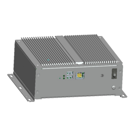
产品介绍 1.3 使用说明 1.3.1 外部功能 设备正视图 位置 描述 复位开关 硬盘指示灯 电源指示灯 USB3/4 网口 2 天线接口 接地螺钉 开关 设备后视图 位置 描述 电源接口 串口 2 串口 3 串口 4 HDMI 接口 串口 1 网口 1 USB2.0 USB3.0 · 4 · MEC-5031-M SERIES... -
Page 13: 内部布局
产品介绍 1.3.2 内部布局 设备开上盖内部布局图 位置 描述 主板 前 IO 板 设备开底盖内部布局图 位置 描述 电源模块 硬盘模块 1.3.3 操作控件 警告 开/关按钮信号不会切断设备电源! 小心 设备执行硬件复位时可能会丢失数据。 MEC-5031-M SERIES · 5 ·... -
Page 14: 状态指示灯
复位按钮。 按钮信号将触 发硬件复位 1.4 状态指示灯 显示 含义 描述 不亮 已从电源断开 POWER 设备状态显示 黄色 待机(休眠) 绿色 设备运行中 不亮 无访问 显示硬盘访问 绿色 访问 不亮 无连接 LAN1 LAN1 状态显示 绿色 数据通信 不亮 无连接 LAN2 LAN2 状态显示 绿色 数据通信 · 6 · MEC-5031-M SERIES... -
Page 15: 应用规划
2.1 运输 包装好的产品能以任何交通工具,运往任何地点,在长途运输时不得装在敞 开的船舱和车厢中,中途转运时不得存放在露天仓库中,在运输过程中不允许和 易燃、易爆、易腐蚀的物品同车(或其他运输工具)装运,并且产品不允许经受 雨、雪或液体物质的淋湿与机械损坏。 2.2 贮存 产品贮存时应存放在原包装箱内,存放产品的仓库环境温度为 0℃~40℃, 相对湿度为 20%~85%。仓库内不允许有各种有害气体、易燃、易爆炸的产品及 有腐蚀性的化学物品,并且无强烈的机械振动、冲击和强磁场作用。包装箱应垫 离地面至少 10cm,距离墙壁、热源、冷源、窗口或空气入口至少 50cm。 小心 损坏设备的风险! 在寒冷天气状况下运输设备时,应注意温度的极端变化。 这种情况下,请确保 设备上或设备内部没有形成水滴(凝露)。如果设备上形成了凝露,请至少等 待 12个小时后再接通设备。 2.3 开箱及检查交付的设备 2.3.1 开箱检查设备 设备开箱时请注意以下几点: 建议您不要丢弃原包装材料。 请保留原包装材料以备再次运输设备时使 用。 请将附带文档存放在安全的地方。 初始调试设备时需用到该文档,并且它 MEC-5031-M SERIES · 7 ·... -
Page 16: 记录设备的标识数据
验证所运货物是否包含完整的设备以及您单独订购的附件。 如有任何不符 或存在运输损坏,请联系客户服务人员。 2.3.2 记录设备的标识数据 注意 在维修时或失窃后,可凭借这些唯一的编号来识别设备,请不要撕毁。 序列号:位于设备箱体(一般位于后侧)(如下图所示) 2.4 外部环境条件 规划项目时,应考虑以下条件: 操作说明提供的规范中所指定的气候和机械环境条件。 请避免极端环境条件。设备应注意防尘、防潮及防热。 请勿使设备受到阳光直射。 请确保其它组件或机柜侧面距设备上方和下方的距离至少分别为 50 mm 和 100 mm。 请勿盖住设备的通风口。 应始终遵守该设备所允许的安装位置要求。 所连接或安装的 I/O 不得在设备中生成大于 0.5 V 的反向电压。 · 8 · MEC-5031-M SERIES... -
Page 17: 安装产品
安装产品 3.安装产品 3.1 安装信息 在安装设备前,请阅读以下安装说明。 注意 在开关柜中进行安装时,请遵守装配准则及相关的DIN/VDE要求或者国家/地 区特定的规章。 3.2 安装方式 □19″上架式 □桌面式(台面式) □嵌入面板式 ■壁挂式 □VESA 标准支撑臂 □手提便携式 □其他方式___________ 3.2.1 壁挂式安装 步骤: 如左图所示, 用螺钉把机 器固定在机柜上 注意事项: 整机一定要放置在托 板上或导轨上, 严禁只用前面板 螺钉固定整机。 警告 确保墙壁或天花板或载体能够承载至少为四倍的设备总重量(包括机柜支架 和附加的扩展模块)。 MEC-5031-M SERIES · 9 ·... -
Page 18: 密闭整机使用环境
密闭整机三维最大尺度为 L,重力方向为 Y,整机上方空间为+Y,下方空间为 -Y,如下面图 1 和图 2 所示。 1、上方区域 +Y > 2L,整机正上方要有大于 2 倍最大尺寸的区域空间; 2、下方区域 -Y > L,整机正下方要有大于 1 倍最大尺寸的区域空间; 3、其它四个方向(前、后、左、右)的区域空间要大于 0.5L; 4、在上述热交换区域空间内不能再有其它发热体或空间隔断物,机箱外壳表上 也不能再放置其它物品; 5、热交换区域空间与其外部的自然环境要有热交换渠道,比如动力排风设备、 保证空气自由流通的进出风口等等; 6、 在距离底部 20~50mm 的下方区域空间的温度不能超过整机的额定工作环境温 度; 7、热交换区域空间内任意一点的空气流动速度不低于 0.2m/s。 图 1 整机三维最大尺度 · 10 · MEC-5031-M SERIES... - Page 19 安装产品 图 2 热交换区域空间 安装时外壳散热翅片顺着机柜内的通风方向会有更好的散热效果, 推荐下面两种 通风方式,如图 3 和图 4 所示。 图 3 左右横向通风 图 4 向上通风 MEC-5031-M SERIES · 11 ·...
-
Page 20: 设备连接
本设备只能在接地电源网络上运行。 禁止在未接地或阻抗接地的电源网络上进 行操作。 警告 使用的设备额定电压必须符合本产品电源特性。 注意 只能连接经认可适合工业应用的外围设备。设备运行时,可以连接热插拔 I/O 模块(USB)。无热插拔功能的I/O设备只能在设备断开电源后进行连接。 4.2 接地连接 低阻抗接地连接更有助于将外部电缆、信号电缆或连接 I/O 模块的电缆所 生成的干扰释放到接地系统。 接地端子 设备上的接地端子 ①(大表面、 大面积接触) 必须与安装有设备的 机柜或设备的中央接地母线连接。 最 小 导 线 横 截 面 不 能 小 于 2.5mm ,接地电阻最大不能大于 0.1Ω。 · 12 · MEC-5031-M SERIES... -
Page 21: 将设备连接到电源
设备连接 4.3 将设备连接到电源 将设备连接到电源的步骤 把配件中的适配器上的端子插入 图示接口①中 危险 雷暴雨期间断开电源和数据电缆。 注意 必须断开电源连接器才能将设备与电源完全隔离。 MEC-5031-M SERIES · 13 ·... -
Page 22: 操作系统
支持操作系统:Linux、Win7、Win8 .2 产品接口定义 5.2.1 DC电源输入插座 提供 1 个 4P 卧式凤凰端子插座, 支持单电源输入, 电压输入范围: 9-30 VDC, 管脚定义如下: 管脚 信号名称 正 负 DC IN 9V-30V 注:SW+、SW-:远程开关机输入信号,ATX 模式下触发 SW+、SW-两脚开关机。 5.2.2 USB接口 1、USB2.0 接口定义 管脚 信号名称 USB_Data- USB_Data+ USB3,USB4 · 14 · MEC-5031-M SERIES... -
Page 23: 网络接口
USB_DATA+ USB_SSRX- USB1,USB2 USB_SSRX+ USB_SSTX- USB_SSTX+ 注:仅 USB1 支持 USB3.0。 2.3 网络接口 LAN1, LAN2 是标 准 RJ45 连接器, 为 10/100/1000Mbps 以太网接口, 其中 LILED 和 ACTLED 是以太网接 口两边的 LED,它们显示着 LAN 的网络速度指示状态和网 络活动指示状态。请参考以下每一个 LED 的状 态描述。 LAN1,LAN2 MEC-5031-M SERIES · 15 ·... -
Page 24: Vga接口
灭 无数据传输 灭 10Mbps 注:千兆网卡不管有/无 Link 信号,左 边的 ACTLED 灯表示的是 有无 数据传输, 有数据传输时,左边的绿色灯应为“闪烁”状态;只连接网络未收发数据时,绿 色灯应为“熄 灭”状态;有 广播包时,ACTLED 灯会“闪烁”属于正常。 5.2.4 VGA接口 提供 1 个标准 DB15 VGA 接口,管脚定义如下: 管脚 信号名称 管脚 信号名称 Green Blue DDCDATA HSYNC VSYNC DDCCLK · 16 · MEC-5031-M SERIES... -
Page 25: 标准Db9 串口
换 径是 B IOS 中 Advanced\Com1&Com2 M tion,B IOS 默 认为 R 32 模式, 用户 可根据 需要选择 RS -422 或 RS-485 模 式。 5.2.6 HDMI接口 提供 1 个 19 Pin Type A 型 HDMI 接口。 MEC-5031-M SERIES · 17 ·... - Page 26 TMDS DATA2 Shield TMDS DATA2- TMDS DATA1+ TMDS DATA1 Shield TMDS DATA1- TMDS D ATA0+ TMDS A0 Shiel DS DATA TMDS CLK+ HDMI1 CLK Sh ield TMDS CLK- D(NC on devi CEC Gro Plug De tect · 18 · MEC-5031-M SERIES...
-
Page 27: 软件介绍
本 公司 有支持 所 BPI 的主板整 机 件访问硬件的统一接口 在 BPI 基础上开发的平台管 理应用软件,方便用户对其 所有支持 BPI 的主板整机均可运 工控 设备 的状 态查询,日志 行 eManager,子功能视具体主板 eManager 管理和工控常用的基本功能 而定 。对 不支持的,可以提供 于 (如 WDT, GPIO,硬 件监控 ) 定制服务 (具体费用请咨询客服) 等 MEC-5031-M SERIES · 19 ·... -
Page 28: Bpi介绍
或 64 位操作系统保护模式下的访问硬件的软件接口规范, 支持多进程和多线程访 问硬件。 BPI 是 硬件和应用软件之间的纽带, 其目的是为应用层提供平台无关的操 作硬件的标准接 口(以库函数的形式呈现 ,类似标准 C 的库函数) ,应用软件工程 师无需关心主板具体的硬件实现方案。用户利用 BPI 库就可以快速开发出自己的 软件产品,而且在主板硬件 升级时,无需修改应用层软 件,原来的软件就可在新 的平台上正常运行。BPI 大大提高了产品的开发速度和降低产品的维护成本。 BPI 架构如 图 1 所示: 图 1 BPI 架构 BPI 支持功能 看门狗 · 20 · MEC-5031-M SERIES... - Page 29 2. BPI 的优点 平台无关性 BPI 向应用层提供的接口,即 BPI 库函数是平台无关的,因此使用 BPI 库函 数开发的软件,无需做任何修改,就可直接在支持 BPI 功能的新硬件平台上 正常运行,具有良好的可移植性。 安全性和可靠性高 访问硬件的 BPI 库函数由主板开发商编写,并经过严格测试,可避免因对系 统硬件操作不当,造成系统异常问题。 易维护 传统方式的 WDT 及 GPIO 编程与硬件密切相关,测试及调试复杂,且需要维 护不同平台的软件,而使用 BPI 库开发的软件,只要维护一套软件即可。 成本低 用户使用 BPI 开发应用程序,不会增加额外的硬件或软件成本。应用软件工 程师利用 BPI 库函数可以很方便地进行二次开发,无需关注具体硬件的访问 MEC-5031-M SERIES · 21 ·...
-
Page 30: Fmi简介
CPU 总的心跳次数。日志管理信息可以为 失效分析和产品升级提供非常有价 值的参考信息。 BPI 库地址:见光盘 中的“Sofware\Chinese\BPI” 或者“Sofware\English\BPI” BPI 库 函数使用手册 安装“BPI X Setup.exe”后,默认自动生成 BPI 库函数使用手册在“开始” →“程序”→“EVOC” → “evoc_bpi_x”中可以找到使用说明。 eManager管理软件介绍 eManager 软件是研祥自主研发的设备管理平台软件。利用 eManager 软件, 可以进 行系统运行异常监测,GPIO 输入输出模式及电平的设置,实时监测温度、 风扇、 电压状态,预测硬盘寿命等功能,帮助客户有效的使用及管理设备。 软件 具有以下功能: 看门狗(WDT) GPIO · 22 · MEC-5031-M SERIES... -
Page 31: 运行环境
盘 SMART 信息 硬 6. 1 运行环境 以 windows 操作系统为例,如果客户需要用 BPI 提供的库函 数,自己开发应 用程序,只需包含 EVO C_BPI_DLL.dll、BPI32.sys、BPI64.sys。如客户需运行, eMan ager 软件,直接解压安装,我们提供的的 BPI3.0 的安装包后,以启动即可。 (win 7 以上的操作系统需以管理员权限运行) 。 6.3. 2 功能 1、欢 界面 迎 软件打开后显示友好的欢迎界面,如下图所示。 2、看门狗(WDT) 看门狗效果图如下所示。 MEC-5031-M SERIES · 23 ·... - Page 32 软件介绍 使用方法:首先进行配置,模式为复位模式,计时单位选择分或者秒,超时 时间范围从 1-255 间任意数字。配置完成后 按左边“开始”按钮,看门狗开始倒 计时工作, “当前计时” 处显示当前倒计时值,复位模式下倒计时等于 0 时机器重 启 ,倒计时过程中可按下“喂狗”按钮将重新开始从配置的超时时间开始倒计时; 按下“停止”按钮为 停止看门狗工作。看门狗正在倒计时时退出程序也会停止看 门狗 工作。 “自动喂狗”选项框选中后,在倒计时过程中,计时时间小于 3 秒自动 喂狗。 功能:可监控系统是否正常运行,并对异常进行复位。当系统出现异常时, 看门狗无法自动喂狗,倒计时结束后系统重启,从系统错误中恢复。 3、GPIO · 24 · MEC-5031-M SERIES...
- Page 33 软件介绍 GPIO 效果图如上图所示。 使用方法:默认状态不启用 GPIO,避免用户程序也存在 GPIO 设置时与之冲 突。GPIO 最大支持 64Pin 显示,界面上超过 8Pin 时以滚动条的形式显示,GPIO MEC-5031-M SERIES · 25 ·...
- Page 34 软件介绍 的输入输出模式在相应的单选框内设置,电位的高低状态用绿灯显示,灯亮表示 高电位,灯灭表示低电位,GPIO 为输出模式时可改变电位状态,通过右边对应的 “设置”按钮切换电位状态。如果是网络型号主板则会把该主板特有的 LED 灯显 示出来,并可进行设置。 功能:进行 GPIO 和 LED 网络灯的设置 4、硬件检测 硬件检测效果图如上图所示。 使用方法:软件切换至硬件检测界面后,自动获取温度、风扇转速、电压等 参数信息,每隔 2S 刷新一次。 功能:实时获取硬件工作状态。 · 26 · MEC-5031-M SERIES...
-
Page 35: 固件管理
软件介绍 6.3.3 固件管理 1、硬盘 SMART 硬盘 SMART 效果图如上图所示。 使用方法:在下拉列表中选择硬盘,然后列表框中则会现在影响硬盘性能的 SMART 信息。 功能:查看影响硬盘性能的 SMART 属性,帮助预测硬盘的使用寿命,避免硬 盘损坏导致数据丢失。 2、开机时间 MEC-5031-M SERIES · 27 ·... -
Page 36: 数据备份
软件介绍 开机使劲效果图如上图所示。 使用方法:选择需要查询的其实时 间和结束时间,查询,然后列表框中则会 赛选 出规定时间跨度内的,机器开关机记录。也能显示非法关机次数。和机器总 运行时间。 功能:监控机器运行状态。记录非法关机次数。 3、用 户编 程 用户可以直 接使用 eManager 软件进行设备的管理, 如果用户打算自己编写软 件,可以参照光盘中附带 VB、VC、C++Builder、Delphi 的完整例程及 BPI 编程接 口使用手册。 6.4 数据备份 6.4.1 EVOC一键还原操作说明(可选) 研祥一键还原功能支持多种文件系统(FAT32/NTFS/EXT2/EXT3/EXT4)分区 · 28 · MEC-5031-M SERIES... - Page 37 当整机中只有一个存储设备时,固定地把该存储设备上的第一个分区备份到 最后一个分区,或固定地把该存储设备上的最后一个分区的备份镜像文件还 原到第一个分区。 整机可以最多支持四个存储设备同时存在,默认将其中一个存储设备为系统 的主盘,最后一个存储设备作为 系统的从盘。默认备份方式是将主盘的第一 个分区的数据保存到从盘的最后一个分区。默认还原方式是把从盘最后一个 分区的备份镜像还原到主盘的第一个分区。 在 MEC-5 031-M SERIES 中,当同时存在 CF 存储卡和硬盘时,CF 存储卡默认 作为整机的主盘,最后一个硬盘则是整机的从盘; 当仅有两个硬盘时,第一 个硬盘默认作为整机的主盘,最后一个硬盘则是整机的从盘。 在 MEC-50 31-M SERIES 中,每个存储设备需要有两个分区,确保备份还原操 作成功。 备份盘分区的文件系统与还原盘的文件系统可以不相同,但两者均不能使用 FAT32/NTF S/EXT2/EXT3/EXT4 以外的文件系统。 第一次还原时,必须确保有备份好的镜像文件(即此前须按上述规则备份数 据) ,否则, 还原动作无效。 二、 操作步骤: MEC-5031-M SERIES · 29 ·...
- Page 38 软件介绍 1. 开启或关闭研祥一键还原功能。 在开机画面起来后,按“Del”键进入 BIOS Setup 配置界面。 (1) 在 BIOS Setup 配置界面中找到 BOOT 项,配置 EVOC Backup 选项开启 [Enable]或关闭[Disabled],来启用或关闭 EVOC 一键还原功能。此项功 能默认是打开。 2. 进入系统备份还原界面。 当开启 EVOC 一键还原功能后,在主板开机时将在显示器上提示“Please Press button<RCV> for System Recovery within 3 Seconds!!”处,此时在 3 秒内按下整机背面的按键<RCV>,将进入系统还原备份界面。 3. 进行系统备份 进入系统备份还原界面,首先会进入到下面的界面,询问用户是否进行一键 还原系统,并有一个 25 秒的读秒倒计时。如果第一次运行此功能,一定要先选择...
- Page 39 软件介绍 A. 一键还原系统 Restore 此选项是自动还原上一次备份系统的镜像。 B. 一键备份系统 Backup 此选项是自动备份第一硬盘的第一 份分区 C. 手动备份还原 Mannual 此选项是手动备份还原,此选项需要专业人士 操作 D. 恢复出厂设置 Default 此选项是清除备份信息。 当数据备份或者还原操作完 毕后,系统将会自动重启。 4、手动备份还原 一键还原的主界面如下,使用上下键选择可以进入手动备份还 原功能,手动备份 功能一般需要专业人士操作,否则可能造成数据的丢失和系统崩溃! 上面的界面选择手动备份还原后,回车进入如下界面: MEC-5031-M SERIES · 31 ·...
- Page 40 软件介绍 该界面下:如需备份选择 Bachup,如果已经备份需要还原那么选择 Restore,下 面是备份的步骤,还原在之后讲到。 Backup 的过程,如下图示: 选择 Full Backup 后如下: · 32 · MEC-5031-M SERIES...
- Page 41 软件介绍 选择驱动接口默认为 BIOS,回车后,选择要备份的设备: 选择要备份的分区: 使用上下键移动,空格键进行选择,如下图示: MEC-5031-M SERIES · 33 ·...
- Page 42 软件介绍 选择 Mutiple File Set,后回车 选 择 File (Direct)方式: · 34 · MEC-5031-M SERIES...
- Page 43 软件介绍 选择默认 Bios,如下图示: 选择备份的目的地位置: 选择备份具体的分区: MEC-5031-M SERIES · 35 ·...
- Page 44 软件介绍 输入备份镜像的文件名,如下图示: 选择压缩的方式以及一些附加的信息,这里可以选择默认值,如下图示: 回车之后,显示备份的概要信息,如下图示: · 36 · MEC-5031-M SERIES...
- Page 45 软件介绍 直接回车之后,启动备份: 等 待备份完成,时间长短视备份文件的大小而定。弹出如下提示,表示备份完成, 如下图示: stor (还原)的过程: 在主菜单中选择 Restore,如下图示: MEC-5031-M SERIES · 37 ·...
- Page 46 软件介绍 回车之后,选择 Automatic 进行自动安装,如下图示: 选择还原的方式,这里直接使用默认值 File(Direct) ,如下图示: · 38 · MEC-5031-M SERIES...
- Page 47 软件介绍 选择驱动接口,这里直接使用默认值 BIOS,如下图示: 选择还原文件的位置,如下图示: MEC-5031-M SERIES · 39 ·...
- Page 48 软件介绍 选择还原文件在分区中的位置,如下图示: 选择还原镜像的文件名: · 40 · MEC-5031-M SERIES...
- Page 49 软件介绍 选择还原文件的目的地位置,如下图示: 警告信息,选择 YES 后回车,如下图示: 警告确认信息,选择 YES 后回车,如下图示: 回车后,显示还原过程的概要信息,如下图示: MEC-5031-M SERIES · 41 ·...
- Page 50 软件介绍 回车后,启动还原过程,如下图示: 等待,弹出以下提示后,表示完成还原工作,如下图示: 注意: 1) 完成率百分比有时候 1 分钟左右不动是正常的,系统在后台运行,请耐心等 待。 2) 备份时间取决于系统盘的大小。 杀 毒功能说明 我司 MBR 杀毒功能集成在 BIOS 中,不被其他软件(包括病毒)破坏,具有 很 好的防护性和安全性。下面是使用杀毒功能的说明。 · 42 · MEC-5031-M SERIES...
- Page 51 软件介绍 在开机阶段,按“Del”键进入 BIOS 配置界面; 在 BIOS 配置界面中的 Security 菜单中有一项功能选项“Clear MBR Virus Function” ;该选项中有三个选择子项: a)Disabled:关闭清除 MBR 病毒功能; b) Manual:检测到硬件系统存在 MBR 病毒时候会在 Post 阶段提示用户是 否清除 MBR 病毒,选择“Y”清除病毒,选择“N”不清除病毒; c) Quiet:检测到硬件系统存在病毒的时候自动清除病毒,没有任何提示 信息。 MEC-5031-M SERIES · 43 ·...
-
Page 52: Bios功能介绍
Press <F2> or <Del> to BIOS Setup,Press <F7> to Boot Menu. BIOS 信息提示界面如上图所示,包括公司及产品相关信息。BIOS 版本和编译 时间,CPU 型号和内存容量等信息。 通过 BIOS Setup 设置程序修改相关设置(除了日期、时间)都保存在系统的 闪存存储器中,即使掉电或拔掉主板电池,其内容也不会丢失;在因误操作无法 进入 Setup 界面时,如需恢复出厂设置,请短接 JCC1 执行清除 CMOS 内容的操作。 注意!BIOS 的设置直接影响到电脑的性能,设置错误的参数将造成电脑 的损坏,甚至不能开机,请使用 BIOS 内置缺省值来恢复系统正常运行。 由于本公司不断研发更新 BIOS,其设置界面也会略有不同,以下的画面 供您参考,有可能跟您目前所使用的 BIOS 设置程序不完全相同。 · 44 · MEC-5031-M SERIES... -
Page 53: Bios基本功能设置
System Date 选择此选项,用< + > / <->来设置目前的日期。以月/日/年的格式来表示。 各项目合理的范围是: Month/月(1-12), Date/日(01-31),Year/年(最大至 2099), Week/星期(Mon.~ Sun.)。 System Time 选择此选项,用< + > / <->来设置目前的时间。以时/分/秒的格式来表示。 各项目合理的范围是:Hour/时(00-23), Minute/分(00-59),Second/秒(00-59)。 System Information 选 择此子菜单,按< Enter > 进入,可以查看系统信息,如板卡名称,BIO 版 本,CPU 型号,内存大小等信息,详细参考下图所示。 MEC-5031-M SERIES · 45 ·... - Page 54 Legacy Boot [Enabled] Boot in Legacy Video Mode [Disabled] Boot Priority [UEFI First] F1 Help ↑↓ Select Item Change Values F9 Setup Defaults Esc Exit ←→ Select Menu Enter Select ▶ Sub-Menu F10 Save and Exit · 46 · MEC-5031-M SERIES...
- Page 55 BIOS Legacy 支持控制开关,当关闭时 BIOS 阶段及 DOS 系统无法使用 USB 设 备。 UEFI Boot UEFI 引导支持开关。 Legacy Boot 传统引导方式支持开关。 Boot in Leagcy V ideo Mode 引导时使用传统显示模式,以兼容个别系统或软件。 Boot Priority 引导方式优先级设置开关,用于调整 UEFI 和 Legacy 引导方式的先后顺序。 MEC-5031-M SERIES · 47 ·...
- Page 56 [0.880 V] VCC3.3V [3.264 V] VCC5V [5.040 V] VCC12V [11.711 V] F1 Help ↑↓ Select Item +/- Change Values F9 Setup Defaults Esc Exit ←→ Select Menu Enter Select ▶ Sub-Menu F10 Save and Exit · 48 · MEC-5031-M SERIES...
- Page 57 USB 控制器模式, 选项 xHCI Controller 与 EHCI Controller 不能 同时 设置成 Enabl e。 SATA Controller Mode 集成 SATA 控制器工作 式选项, 模 有 AHCI,IDE 被选项。 SD Card Support SD 卡支持开关选项 Power State 用于选择系统上电行为, Power On,系统上电即开机,Power Off,系统 MEC-5031-M SERIES · 49 ·...
- Page 58 Esc Exit ←→ Select Menu Enter Select ▶ Sub-Menu F10 Save and Exit Secure Boot Activation 安全引导激活选项,该选 项需设置 Supervisor Password 才能使用,该选项 一经设置 Enable,无法关闭。 Secure Boot Config uration Supervisor Password 才能使用 安全引导相关设置子菜单。该子菜单需设置 Supervisor/User Password is: · 50 · MEC-5031-M SERIES...
- Page 59 时,进入 Setup 时需要输入用户密码,该 项需要设 置 Supervisor Password 才能使用。 HDD Password Select 用于选择硬盘密码权限,有 User Only/Use r+Master 被选项。该选项只有 接硬盘时才显示。 HDD Security Status 用于显示硬盘安全信息状态 列表,如没有侦测到硬盘,会显示 No HDD Detected,如有侦测到硬盘会显示对应的 HDD Password State 状态,和 Set HDD User Password 选项,用于查看硬盘密码状态和设置硬盘密码功 能。 MEC-5031-M SERIES · 51 ·...
- Page 60 Save Changes configure driver. Finally resets the system automatically. F1 Help ↑↓ Select Item +/- Change Values F9 Setup Defaults Esc Exit ←→ Select Menu Enter Select ▶ Sub-Menu F10 Save and Exit · 52 · MEC-5031-M SERIES...
-
Page 61: X86 平台下Bios所要管理的系统资源
Memory 地址。 IO端口地址 X86 的 I/O 地址线只设计 16 条,从 0~0FFFFh,I/O 地址空间总共有 64K, 在传 统的 ISA 接口,只使 用到前面的 1024 个(0000~ 03FFh) ,0400h 以上的端口 为 I 接口与 EISA 接口所使用。每一外围设备都会占用 一段 I/O 地址空间。下表 给出了 X86 平台大致上所要用到的 I/O 接口列表。 MEC-5031-M SERIES · 53 ·... - Page 62 0065-0065 Motherboard resources 0067-0067 Motherboard resources 0070-0070 Motherboard resources 0070-0077 System CMOS/real time clock 0078-0CF7 PCI bus 0080-008F Motherboard resources 0092-0092 Motherboard resources 00A0-00A1 Programmable interrupt controller 00A4-00A5 Programmable interrupt controller 00A8-00A9 Programmable interrupt controller · 54 · MEC-5031-M SERIES...
- Page 63 标准 AHCI 1.0 串行 ATA 控制器 3020-303F 标准 AHCI 1.0 串行 ATA 控制器 3040-3047 标准 AHCI 1.0 串行 ATA 控制器 3048-304F 标准 VGA 图形适配器 3050-3057 标准 AHCI 1.0 串行 ATA 控制器 3058-305B 标准 AHCI 1.0 串行 ATA 控制器 305C-305F MEC-5031-M SERIES · 55 ·...
- Page 64 通讯端口(COM4) IRQ12 PS/2 兼容鼠标 IRQ13 保留 IRQ14 保留 IRQ15 保留 APIC 高级可编程 断控制器。在现代 P4 以上级别的 中 主板中,大都支持 APIC,可 以提 供多于 16 个 断源, 如 IRQ16—IRQ23, 部分主板 中 如支持 PCI-X 的主板可以有 多 达 28 个中断源。但要启用该功能必须相应的操作系统支持。 · 56 · MEC-5031-M SERIES...
- Page 65 FED00000-FED003FF High precision event timer FED01000-FED01FFF Motherboard resources FED03000-FED03FFF Motherboard resources FED04000-FED04FFF Motherboard resources FED08000-FED08FFF Motherboard resources FED0C000-FED0FFFF Motherboard resources FED1C000-FED1CFFF Motherboard resources FEE00000-FEEFFFFF Motherboard resources FEF00000-FEFFFFFF Motherboard resources FF000000-FFFFFFFF Intel(R) 82802 Firmware Hub Device MEC-5031-M SERIES · 57 ·...
-
Page 66: 扩展安装
扩展安装 8.扩展安装 8.1 打开设备 小心 仅能由经过授权和符合条件的人员来打开设备。 在保修期内, 只允许用户安装 扩展内存和扩展卡模块 小心 设备包含的电子元件可能 会被静电电荷损 坏。 因此, 打开设备前需要采取预防 措施。 请参见“ESD 准 则”中有关操作静电敏感组件的 ESD 准则 准 备工作 将 设备与电源隔离。 打开设备的步骤 卸掉如图四颗螺钉 卸下安装支架 卸掉如图四颗螺 钉,卸 下底盖 · 58 · MEC-5031-M SERIES... -
Page 67: 硬盘扩展
扩展安装 8.2 硬盘扩展 小心 只能由经授权的合格人员更换驱动器 安装硬盘 安装步骤 打开 底盖 把硬盘支架对准硬盘安 装孔位后,锁紧安装硬 盘的4颗螺钉 按图示位置放置上面装 好的硬盘模块,并锁紧 图示螺钉 合上设备 MEC-5031-M SERIES · 59 ·... -
Page 68: Sim卡扩展
扩展安装 拆卸硬盘 拆卸步骤 打开底盖 拔下连接硬盘的线材并 按图示卸下固定硬盘模 块的螺钉,取下硬盘模块 如图示,卸下固定硬盘的 4颗螺钉,取下硬盘支架 8.3 SIM卡扩展 备注:3G模块、SIM卡需要出厂前安装。 · 60 · MEC-5031-M SERIES... -
Page 69: 设备维护
9.设备维护 .1 卸下和 安装硬件组件 9 .1 执行维修 只能由经过授权的人员对设备进行维修。 警告 未经授权擅自打开或对设备维修不当可导致设备的严重损坏或危及用户安全。 每次打开设备前将设备与电源断开。 仅安装专为此设备设计的系统扩展设备。如果安装其它扩展设备,可能会 损坏该设备或违反关于射频抑制的安全要求和规章。请联系技术支持团队 或设备购买地,以了解可安全安装的系统扩展设备。 如果因安装或更换系统扩展设备而将设备损坏,担保将失效。 责任范围 对因使用第三方设备或组件而造成的功能损害,本公司不承担任何责任。 9.1.2 预防性维护 为了保持较高的系统可用性,我们建议对易磨损设备组件进行预防性更换。下表 给出了这种更换的时间间隔。 组件 更换时间间隔 硬盘 3 年 CMOS 备用电池 5 年 9.1.3 更换备用电池 更换电池前的注意事项 MEC-5031-M SERIES · 61 ·... - Page 70 小心 废弃电池必须按照当地法规来处理。 准备工作 说明 1.记下 BIOS Setup 的当前设置或将设置保存为 BIOS Setup “ 退出” Exit) 菜 单中的用户配置文件。 2.在 BIOS 说明中提供了一个列表,可在其中记下这些信息。 3.将设备 与电源断开 更换电池 更换电池的步骤 卸下固定上盖的4颗螺钉,打开上盖 拔 下 如 图 所 示 电 池 连 接 线,卸 下电池 · 62 · MEC-5031-M SERIES...
-
Page 71: 驱动程序安装说明
设备维护 将新电池背胶的离型纸揭 掉,贴在主板对应位置, 并用胶布加固,再电池连 接线插入主板对应插座里 盖上上盖并用螺钉锁紧 重新组 态 BIOS Setup 如果更换电池的时间超过 30 秒,设备的组态数据将丢失。 这种情况下需 要重新组态BIOS Setup。 驱动程序安装说明 本产品的驱动程序安装及主板详细信息请参考整机配套光盘,在此不做介 绍。 MEC-5031-M SERIES · 63 ·... -
Page 72: 技术参数
技术参数 10.技术参数 10.1 辅助组件的最大功耗 辅助组件 允许的最大功耗 最大总功率 +3.3V +12 V -12 V 7.5W (适用于 USB2.0 强电流 500Ma USB2/3/4 设备 设备) USB3.0 5W(适用于 强电流 900Ma 设备 USB1设备) · 64 · MEC-5031-M SERIES... -
Page 73: 尺寸图
尺寸图 11.尺寸图 11.1 尺寸图概述 本节包含以下尺寸图: 产品外形尺寸图 带有安装支架的产品的尺寸图 说明 尺寸图中的单位通常为毫米 11.2 产品外形尺寸图 单位:mm MEC-5031-M SERIES · 65 ·... -
Page 74: 安装尺寸图
尺寸图 11.3 安装尺寸图 11.3.1 带有安装支架的产品的尺寸图 12.5 单位:mm · 66 · MEC-5031-M SERIES... -
Page 75: 常见故障分析与解决
外 接 显 示 器 不 到显示器和系统单元或接地 亮 出口。 未连接电源线或显示器电 2、检查显示器电缆是否正确地 缆 连接到系统单元和显示器。 3、如果执行这些检查后显示器 屏幕仍不亮,请与技术支持 联系。 根据开机画面提示的按键, 打开 PC 上的时间或 BIOS 设置不正确 BIOS Setup,在 BIOS Setup 中 日期不正确。 调整时间和日期。 BIOS 设 置 正 确, 时间和日期 备用电池电量不足 更换电池 不对。 MEC-5031-M SERIES · 67 ·... - Page 76 到系统盘 winpe 系统) ,检查硬盘系统是 硬盘系统文件损坏 否已损坏, 有必要时最好重新安 装系统。 即插即用 I/O 一般是由于 PCI 或 ISA 卡频繁的 卡设备, 再次使 拔插、固定不稳、防尘措施不好 用 时 检 测 不 到 插槽接触不良 等造成插槽接触不良所致, 可反 或 不 能 正 常 使 复拔插几次或者换个槽插。 用。 · 68 · MEC-5031-M SERIES...
-
Page 77: 常见报警信息分析与解决
Award BIOS主板,开机POST阶段,屏幕 主板或整机未连接PS/2或USB键盘, 显示错误信息“Keboard error or no 需要正确接入键盘 keyboard present” EFI BIOS主板开机POST阶段,听到“滴 主板或整机未连接PS/2或USB键盘, -滴-滴-滴-滴”5声滴的响声 需要正确接入键盘 整机搭配冗余电源 ,当开机后,整机电 冗余电源没有同时接入2个AC插头, 源位置发出刺耳的报警声 需要关机重新接入2个AC插头 12.3 ESD 准则 ESD的定义 所有电子模块都配备了大规模集成化的 IC 或组件。 由于其自身设计原因,这 些电子元件对过电压极其敏感,因此对任何静电放电都极为敏感。 静电敏感组件/模块通常被称为 ESD设备。 这也是此类设备的国际通用缩略语。 可通过以下符号来识别 ESD 模块: MEC-5031-M SERIES · 69 ·... - Page 78 附录 小心 SD 设备可被远低于人 类能感知阈值的电压所损 坏。 如果您接触设备的元件或 电气连接时未释放身体中存在的静电电荷,将产生静 电电压。 静电放电电流可 能会导致模块出现潜在问题,损坏或许不会在当时表现得很严重,但运行中可能 导致故障。 静电充电 未与周围电位相连的人体中会发生静电充电现象。 以下数据显示了人体与指定材料接触时可能产生的最大静电电压。 这些值符合 IEC 801-2规范。 操作员身上的静电电 压 防止静电放电的基本保护措施 确保良好的等电位连接: · 70 · MEC-5031-M SERIES...
-
Page 79: 缩略语列表
必 使用接地的测量仪器。 2.4 缩略语列表 缩略语 术语 含义 交流 交流 ACPI 高级组态与电源接口 可编程控制器 加速图形端口 高速总线系统 SATA设备的标准控制器接 口。 Microsoft Windows XP(高于 AHCI 高级主机控制器接口 SP1 版本)和 IAA 驱动程序 支持该接口 APIC 高级可编程中断控制器 扩展的可编程中断控制器 用于监视和降低设备功耗的 高级电源管理 工具 自动化系统 ASIS 售后信息系统 MEC-5031-M SERIES · 71 ·... - Page 80 光盘 - 可重写 可重写 CD 产品符合所有适用的 EC 指 欧洲共同体(CE 符号) 令 CF 卡 彩色图形适配器 标准监视器接口 时钟脉冲 用于控制器的时钟信号 CMOS 互补金属氧化物半导体 互补金属氧化物半导体 Microsoft Windows 产 品 密 真品证书 钥 许可证书 许可证授权 通信端口 串行接口的术语 通信处理器 通信计算机 中央处理单元 阴极射线管 加拿大标准协会 按照本国或两国标准(使用 · 72 · MEC-5031-M SERIES...
- Page 81 直接存储器存取 磁盘操作系统 无 GUI 的操作系统 分布式 I/O 德国质量与环境管理体系认证 机构 DDRAM 双数据随机存取存储器 带有高 速接口的存储器芯片 数据设置就绪 操作就绪 数据终端就绪 数据终端就绪 数字多功能光盘 数字多功能光盘 数字视频接口 数字显示器接口 具有数字和 VGA 信号的数字 DVI-I 数字视频接口 显示接口 错误修正代码 错误修正代码 扩展的功能端口 扩展的并行端口 增强型图形适配器 设备与监视器的接口 静电荷敏感组件 电子手册 MEC-5031-M SERIES · 73 ·...
- Page 82 用 EPROM/EEPROM 芯 片 的 子可擦写可编程只读存储器 插件子模块 增强型并行端口 双向 Centr onics 接口 退出字符 控制字符 增强型写入过滤 常见问题解答 FAT 32 32 位文件分配表 位文件分配表 FBWF 基于文件的写入过滤器 软盘 磁盘驱动器,3.5" 前端总线 接地 机壳接地 硬盘 硬盘 高保真音频 硬盘驱动器 高度单位 人机界面 用户界面 HORM 一次休眠多次快速启动 超线程 · 74 · MEC-5031-M SERIES...
- Page 83 的数据输入/输出 Intel 应用程序加速器 集成设备电子部件 国际电工委员会 集成的图形设备 入口保护 防护等级 红外 红外 用于通过 IR 模块传输数据 IRDA 红外数据协会 的标准 中断请求 中断请求 工业标准体系结构 用于扩展模块的总 线 信息技术设备 二级缓存 局限于本地 区域的计算机网 局域网 络 液晶显示器 液晶显示器 发光二极管 发光二极管 行式打印机 打印机端口 LVDS 低电压差分信号 MEC-5031-M SERIES · 75 ·...
- Page 84 多语言用户界面 Windows 的 语言本地化 不适用 Normenarbeitsgemeinschaft for Mess- und Regelungstechnik in der NAMUR chemischen Industrie(化工 行业测量和控制技术标准协 会) 未连接 未连接 自 动将文件和磁盘存取重新 原生命令队列 排序, 以提高性能 美 国电子部件制造商联合组 NEMA 美国国家电气制造商协会 织 不可屏蔽中断 无法拒绝中断处理器 NTFS 新技术文件系统 ndows 版本(2000、XP、 · 76 · MEC-5031-M SERIES...
- Page 85 行、 差分全双工 PtP 接口。 PCMCIA 个人计算机存储卡国际协会 保护性接地 保护导体 PCI Express 图形 编程PC 可编程中断控制器 可编程中 断控制器 POST 开机检测 用于通过网络运行没有 硬盘 预引导执行环境 数 据的新设备的软件 RAID 独立磁盘冗余阵列 冗 余硬盘阵列 在受限制访问的操作设施 (例 受限的访问位置 如, 上锁的控制柜)中安装设 备 随机存取存储器 振铃输入 呼入 只读存储器 MEC-5031-M SERIES · 77 ·...
- Page 86 二级缓存 SMART 自我监视、分析和报告技术 硬盘错误诊断程序 短消息服务 通过电信网络传输短消息 SNMP 简单网络管理协议 网络协议 SO-DIMM 小型双内联内存模块 主板上的安全卡(SOM) 标准并行端口 并行端口的同义词 SRAM 静态随机存取存储器 静态 RAM 固态驱动器 使用了至少 256 种颜 色的增 SVGA 超级视频图形阵列 强型 VGA 标准 设备的序列号 软件 Total Cost of Ownershi p(总 · 78 · MEC-5031-M SERIES...
- Page 87 图 形 标 准 , 昀 大 分 辨 率 为 UXGA 极速扩展图形阵列 00x1200 像素。 通 过 串 行 端 口 传 输 数 据 的 V.24 ITU-T 标准化建议 集成电路的正极电源电压 Verein deutscher Elektrotechniker(德国电气 工程师协会) 视频图形阵列 满足工业标准的视频适配器 电压调整模块 虚拟化技术 通过 Intel 技术可以使用模 MEC-5031-M SERIES · 79 ·...
-
Page 88: 词汇表
图 形 标 准 , 最 大 分 辨 率 为 扩展图形阵列 24×768 像素 12.5 词汇 表 AHCI 模式 AHCI 是对 SATA 控制器进行寻址的标准方法。 AHCI 描述了 RAM 中的结构, 其中包含用于控制和状态的常规区域以及一个命 令列表。 APIC 模式 高级外围设备中断控制器。共有 24 条中断线。 ATAPI CD-ROM 驱动器 · 80 · MEC-5031-M SERIES... - Page 89 CF-I (42.6×36.4×3.3 mm) 和 CF-II (42.8×36.4×5mm)。 COM 接口 COM 接 口是串行 V.24 接口。 该接口 适用于 异步数据传输。 说明 关于 Electromagnetic Compatibility (电磁兼容) 的说明。 符合标准由 CE 符号和 EC 一致性证书确认。 ESD 说明 使用静电敏感组件的说明。 Intel VT 英特尔虚拟化技术 (IVT, Intel Virtualization Technology) 为应用程序 MEC-5031-M SERIES · 81 ·...
- Page 90 PC 卡 个人计算机存储卡国际协会(PCMCIA)的商标。 符合 PCMCIA 规范的辅助 卡的标识。与信用卡大小大致相同的PC卡可插入 PCMCIA 插槽。 版本 1 指定厚 度为 3.3 毫 米、主要用作外部存储器的 I 型卡。 PCMCIA 规范的版本 2 也定 义了厚度为 5 毫米的 II 型卡和厚度为 10.5 毫米的 III 型卡。II 型卡可以 实现例如调制解调器、传真卡和网络接口卡等设备。III 型卡配备有需要更多空 间的设备(例如,无线通信模块)或旋转存储介质(例如,硬盘)。 · 82 · MEC-5031-M SERIES...
- Page 91 卡的小型化和灵活使用提供国际标准,以便为市场提供基本的技术。 PEG 接口 用 于图形的 PCI Express。具有 16 个 PCIe 通道的图形接口,用于扩展图 形模块。 PIC 模式 外围设 备中断控制器。共有 15 条中断线。 POST 打 开计算机后 BIOS 执行的自检。 例如, 执行 RAM 测试和图形控制器测试。 如果 BIOS检 测到任何错误,则系统会输出音频信号(蜂鸣声代码);在屏幕上 会输出指示错误原因的相关消息。 PROFIBUS/MPI Process Field Bus(过程现场总线)(过程应用程序的标准总线系统)。 MEC-5031-M SERIES · 83 ·...
- Page 92 Redundant Array of Independent Disks(独立磁盘的冗余阵列): 数据 存储系统, 一般至少在两个硬盘卷上存储数据及相应错误修 正代码 (例如奇偶位) 以提高可靠性和性能。硬盘阵列由管理程序和用于错误修正的硬盘控制器控制。 RAID 系统通常在网 络服务器中实现。 Read-O nly Memory(ROM)是只读存储器,可以单独寻址其中的每个存储地 址。 程序或数据永久存储,电源故障时不会丢失。 S.M.A.R. 自监视、分析和报表技术(SMART 或 S.M.A.R.T.)是集成在存储介质 中的 工业标准。通过该技术可持续监视重要参数并在早期检测到即将发生的问题。 SATA 硬盘驱动器和光驱的串行 ATA 接口,串行数据的传输速率高达 300 Mbps。 SCSI 接口 用于连接 SCSI设备(例如硬盘驱动器或光驱)的小型计算机系统接口。 · 84 · MEC-5031-M SERIES...
- Page 93 SSD(固态驱动器) 固态 驱动器的安装方式与任何其它驱动器类似, 它仅使用容量接近的半导体 存储 芯片,因此不包含旋转磁盘或其它运动组件。这种设计使得 SSD 更为坚固 耐用,同时可以缩短存取时间并降低能耗。 WLAN Wireless LAN(无线 LAN)是本地网络,它通过无线电波、红外线或其它无 线技术传输 数据。 无线 LAN 主要应用于办公室或工厂环境中的便携式计算机。 备份 程序、数据介质或数据库的副本,用于归档或 用于保护关键、不可替换的数 据,防止工作副本损坏时数据丢失。 某些应用程序自动生成数据文件的备份副 本,并 管理硬盘上的当前和先前的版本。 波特 信号传输中步进速度的物理单位 。 定义每秒钟传送的信号状态的数目。 只 有两种状态时,一波特等于 1 bps 的传输率。 操作系统 MEC-5031-M SERIES · 85 ·...
- Page 94 技术(多线程)允许并行计算多个进程。 仅当支持所有相关的系统组件 (例 如处理器、操作系统和应用程序)时,HT 才有效。 传统 USB 支持 (Legacy USB support) 不使用驱动程序支持 USB 端口上的 USB设备(例如鼠标、键盘)。 传统的 启动设备 传统的驱动器可用作 USB设备。 存储卡 信用卡格 式的存储卡。 存储用户程序和参数(例如可编程模块和 CP)的存 储器 。 复位 硬 件复位: 使用按钮/开关复位/重启设备。 格式化 将磁性数 据介质上的存储空间初级划分为磁道和扇区。 格式化操作将删除数 据介 质上的所有数据。所有的数据介质在首次使用前,必须进行格式化。 · 86 · MEC-5031-M SERIES...
- Page 95 附录 常见故障 错误原因、原因分析、补救措施。 缓存 用于所请求数据的中间存储(缓冲)的高速访问缓冲区。 即插 即用 通常指计算机自动组态系统以便与外围设备(例如监视器、调制解调器或打 印机)通信的能力。用户可以插入一个外围设 备并可立即“使用”而无需手动组 态系统。 即插即用设备需要支持即插即用的 BIOS 和即插即用扩展卡。 集线 器 网络技术中的一个术语。 网络中的一个设备,它在一个中央位置连接多个 通信线路,为网络上的所有设备提供公共连接。 可扩 展的固件接口 (EFI) 指的是固件与计算机的各个组件以及操作系统间的中央接口。 EFI 在逻辑上 位于操作系统之下,是设备BIOS 的继任规范 ,主要面向 64 位系统。 控制器 控制某些内部或外围设备的功能的集成硬件和软件控制器(例如键盘控制 器)。 冷启动 MEC-5031-M SERIES · 87 ·...
- Page 96 模块固定架用于固定模块并确保安全接触和运输。 撞击和振动特别影 响大 而重的模块。因此建议对这种类型的模块使用模块固定架。 市场上也有短、轻、 紧凑的模块。 模块 固定架不是为这些模块而设计,因为对它们而言,标准的固 定措 施已足够。 暖启动 中止程序后重启计算机。 加载并再次重启操作系统。 可使用热键 CTRL+ ALT+ DEL 执行暖启动。 驱动程 序 操作系统的程序部分。 它们按 I/O设备(例如 硬盘、打印机和监视器)需 要的特定格式修改用户程序数据。 热插 拔 SATA 接口为设备的硬盘驱动器系统提供了热插拔功能。该组态的前提条 件 是一个带有SATA RAID 控制器(板载或插槽模块)的 RAID1 系统以及至少两个 · 88 · MEC-5031-M SERIES...
- Page 97 附录 SATA 拆卸式托架。热插拔的优势在于无需重新启动计算机就可更换有故障的硬 盘。 双核 C 与上一代使用超线程技术的单核处理器相比, 双核处理器显 著提高了计算和 程序执行的速度。 像素 PixElement(像素)(画面点)。 像素表示可在屏幕或打印机上复制的最 小元素。 芯片组 位于主板上,将处理器与 RAM、图形控制器、设备I 总线和外部接口连接在 一起。 以太网 局域网络内(总线结构)进行文本和数据通信时的传输率为 10/100/1000 Mbps。 引导盘 引导盘即为具有“引导”扇区的引导程序盘。 它可用于从磁盘装载操作系 统。 映像 MEC-5031-M SERIES · 89 ·...
- Page 98 附录 指硬盘分区的映像,例如,保存到一个文件中以便在必要时进行恢复。 重启 不 关闭电源暖启动计算机 (Ctrl + Alt + Del) 主板 主 板是计算机的核心部分。 在主板处理和存储数据并控制和管理接口和设 备I/O。 · 90 · MEC-5031-M SERIES...
- Page 99 OC Product Please pay attention to the following instructions: Warning EVOC product can only be used according to the descriptions within the manual, including the contents and the relevant technical documents. If the products or components fro m other companies are required, please get the recommendation and grant from EVOC first.
- Page 100 Trademarks EVOC is a registered trademark of EVOC Intelligent Technology Co., Ltd. Other product names mentioned herein are used for identification purposes only and may be trademark and/or registered trademarks of their respective companies.
- Page 101 About this manual Scope of the Manual The manual is appropriate for EVOC MEC-5031-M SERIES. Convention The term “the PC” or “the Product” within the manual usually stands for EVOC MEC-5031-M SERIES products. Instructio Safety instructions To avoid p roperty losses or individual injury, please pay attention to the safety instructions within the manual.
- Page 102 Safety Instructions General Safety Instructions Caution Please do not expand your device unless you have read related safety instructions. This product is compliant with safety requirements related to information technology. If you have any question or doubt about effectiveness of installation in the planned environment, please contact your service representative.
- Page 103 ESD Instructions following label can be u sed to identify the modules that contain electrostatic sensitive devices: n operating the modules that contain electr ostatic sensitive devices, please follow th e instructions b elow: When operating the modules that contain electrostatic sensitive devices, make sure to releas e static electricity on your body (for example, by touching a grounded object).
- Page 104 Contents 1. Product Introduction ....................1 1.1 Overview .......................1 1.2 Specifications ....................1.3 Ope rating Instructions ...................4 1.3.1 External Functions................1.3.2 Internal Layout ..................5 1.3. 3 Operation Control................6 1.4 Status LED ....................7 2. Application Scheme ....................8 ..8 2.1 Transportation.................... 2.2 Storage......................
- Page 105 6.3.2 Function...................27 6.3.3 Firmware Management..............30 6.4 Data Backup ....................33 6.4.1 EVOC One-Button-Recovery Operating Instructions (Optional)..33 7. BIOS Setup ......................49 7.1 BIOS Information Interface.................49 7.2 Basic Function Setting for BIOS ..............50 7.3 System Resource Managed by BIOS under X86 Platform ......58 8.
- Page 106 8.3 SIM Card Expansion ...................66 9. PC Maintenance......................67 9.1 Removal/Installation of Hardware Assembly ..........67 9.1.1 Carry out Maintenance ..............67 9.1.2 Preventative Maintenance ...............67 9.1.3 Replacing Backup Battery ...............68 9.2 In stalling the Drivers ...................69 10. Technic al Parameters ....................70 10.1 Maximum Power Consumption of Accessory Assemblies......70 11.
-
Page 107: Product Introduction
It can be used in a wide range of harsh environments, such as heavy contamination, heavy dust and serious EMC, etc. MEC-5031-M SERIES products are designed for highroad lane control, machinery testing equipment, machinery testing equipment, intelligent traffic, industrial autom ation control, etc. -
Page 108: Specifications
RS-232 mode; it does not support Wake-up External IO by Modem. ports 2 x USB2.0 ports and 2 x USB3.0 ports Note: Only USB1 supports USB3.0 standard. 2 x LAN port (RJ45) · 2 · MEC-5031-M SERIES... - Page 109 GB/T 17626.2.2006 ESD Level(2) GB/T 17626.4-2006 Burst Immunity Level(2) GB/T 17626.5-2008 Surge(impact) immunity Level(2) GB/T 17626.6-2008 Conduction Immunity L evel(2) MTBF≥ 100000h ELIABILITY MTTR≤0.5h Meets basic requirements for GB4943 Safety MEC-5031-M SERIES · 3 ·...
-
Page 110: Ope Rating Instructions
Power con sumption of the PC: 13.6W(operating Win7 100% ) Operatin g Instructions 1.3. 1 External Functions Front View Location Description Reset button HDD LED Power LED USB3/4 LAN2 Antenna port Ground screw Switch · 4 · MEC-5031-M SERIES... -
Page 111: Internal Layout
Product Introduction Rear View Location Description Power connector COM2 COM3 COM4 HDMI port COM1 LAN1 USB2.0 USB3.0 1.3.2 Internal Layout Internal Layout of the PC Location Description Motherboard Front IO board MEC-5031-M SERIES · 5 ·... -
Page 112: Operation Control
1.3.3 Operation Control Warning The On/Off button signal will not disconnect PC power supply! Caution When the PC executes hardware reset, data may be lost. Control Button Location Description On/Off button used switch on/off e PC. · 6 · MEC-5031-M SERIES... -
Page 113: Status Led
POWER Displaying PC status Yellow Standby(hibernate) Green PC is operating No access Displaying hard drive status Green Being accessed Not linked LAN1 LAN1 status ata c ommunication Not linked LAN2 LAN2 status Green Data communication MEC-5031-M SERIES · 7 ·... -
Page 114: Application Scheme
(condensation) is formed on the surface or interior of the device. If cond ensation is formed on the de e, please wait for over twelve hours before connecting the device. · 8 · MEC-5031-M SERIES... -
Page 115: Opening The Box And Initial Examination
, these code s can be used to identify the PC. Please do not rip them off. Seria l number: located o n the chassis b ody (as s hown below) MEC-5031-M SERIES · 9 ·... -
Page 116: External Environment Conditions
Please do not block the ventilation hole of the PC. The installation position requirement for the PC should be always observed. The conn ected or installed I/O should not generate reverse voltage of more than 0.5V inside the PC. · 10 · MEC-5031-M SERIES... -
Page 117: Product Installation
Warning Please make sure the total carrying capac ity of the wall or ceiling is at least four times as much as the total weight of the PC (including cabinet bracket and accessory expansion modules). MEC-5031-M SERIES · 11 ·... -
Page 118: Application Environment Of Fully-Enclosed Computer
6. The temperature of lower space (20~50mm from the bottom of the PC) should be no more than the rated operating environment temperature of the PC; 7. At any point in the heat exchange area, the air flow speed should not be lower than 0.2m/s. · 12 · MEC-5031-M SERIES... - Page 119 . Two ventilation methods are recommended, as shown in th e Picture 3 and Picture 4. Figure 3 Left-right transverse ventilation MEC-5031-M SERIES · 13 ·...
- Page 120 Product Installation Figure 4 Upward ventilation · 14 · MEC-5031-M SERIES...
-
Page 121: Pc Connection
PC or the central grounding busbar on the device. The minimum cross section area of the cable shall be no less than 2.5mm . The maximum ground resistance should be no more than 0.1Ω. MEC-5031-M SERIES · 15 ·... -
Page 122: Connecting The Device To Power
Danger Disconnect the power source and data cable during a lightning storm. Attention The PC is completely isolated from the power supply only by disconnecting the power connector. · 16 · MEC-5031-M SERIES... -
Page 123: Debugging
Positive Negative DC IN 9V-30V Note: SW+, SW-: remote switch-on/off input signal, to trigger switch-on /off of SW+ and SW- under ATX mode. .2.2 USB Port . USB2.0 port definition Signal Name USB_Data- USB_Data+ USB3,USB4 MEC-5031-M SERIES · 17 ·... -
Page 124: Network Port
LILED and ACTLED are two LEDs on both sides of the Ethernet port, which respectively indicates network speed and network activity status. Please refer to the following for the status description of each LED: LAN1,LAN2 · 18 · MEC-5031-M SERIES... -
Page 125: Vga Port
LED is “off”; when there are broadcasting packages, it is normal if the ACTLED is “flashing”. 5.2.4 VGA Port The product provides one standard DB15 VGA port. Its pin defi nition is as follows: Signal Name Signal Name Green Blue DDCD HSYNC VSYNC DDCCLK MEC-5031-M SERIES · 19 ·... -
Page 126: Standard Db9 Com Ports
The setup path is Advanced\Com1&Com2 Mode Selection in the BIOS. BIOS is RS-232 mode by default, and users can select RS -422 or RS-485 mode according to their needs. 5.2.6 HDMI Port The produ ct provides one 19 -Pin Type A HDMI port. · 20 · MEC-5031-M SERIES... - Page 127 TMDS DATA2- TMDS DATA1+ TMDS DA TA1 Shield TMDS DATA1- TMDS D ATA0+ TMDS DA TA0 Shie TMDS DATA0- TMDS CLK+ HDMI1 TMDS CLK Shield TMDS CLK- RSVD(NC on device) DDC/CEC Ground Hot Plug Detect MEC-5031-M SERIES · 21 ·...
-
Page 128: Software Introduction
6. Software Introduction Software Description Supported Range Name BIOS programming interface All supporting BPI specification, which provid motherboards an d PCs of EVOC unified interface for softw are to company access hardware. A platform mana All th other boards /complete... -
Page 129: Bpi Overview
Software Introduction 6.1 BPI Overview EVOC BPI (BIOS P rogramming Interface) is a cros -platfor m, easy-to-maintain software interface specification, which supports access to hardware under the Protected Mode of 32-bit or 6 4-bit operating sy stem a suppo rts multi-process multi-threading hardware a ccess. - Page 130 Security and High Reliability The BPI function library accessing the hardware is programmed by the motherboard developer and is strictly tested; therefore, it can avoid system malfunction caused by improper operation of the system hardware. · 24 · MEC-5031-M SERIES...
-
Page 131: Fmi Overview
PC, total heart beat times of the CPU. eLog management information can provide valuable reference for failure analysis and product upgrade. BPI library address: please see “Software\Chinese\BPI” Or “Software\English\BPI” in the enclosed CD MEC-5031-M SERIES · 25 ·... -
Page 132: Emanager Software
”→“Program”→“EVOC” →“evoc_bpi_x”. 6.3 e Manager Software eManager software is a devi ce management platform software developed by EVOC. eMan ager software can be used for system operation abnormality monitoring, setup of GPIO input/output mode and electrical level, real-time monitoring of temperature, fan and v oltage status. -
Page 133: Function
3 seconds, Watchdog will be automatically fed. Function: Monitors whether the system can be normally operated, and carry out reset for abnorma lity. When abnormality occurs to the system, W atchdog cannot be fed MEC-5031-M SERIES · 27 ·... - Page 134 Software Introduction automatically. After counting-down is finished, the system will restart, and recover from system error. 3. GPIO · 28 · MEC-5031-M SERIES...
- Page 135 “Setup” button on the right. If it is a network-type motherboard, the special LED of the motherboard will also be displayed and can be set up. Function: Setup of GPIO and Network LED 4. Hardware Detection MEC-5031-M SERIES · 29 ·...
-
Page 136: Firmware Management
Method: After the software switches to hardware detection interface, it will utomatically acquire temperature, fan speed, voltage and other information, refreshing at a 2S interval. Function: real-time acquisition of hardware operating status. 6.3.3 Firmware Management 1、HDD SMART · 30 · MEC-5031-M SERIES... - Page 137 HDD performance will be displayed in the list box. Function: To check SMART information related to HDD performance, which helps predict service life of HDD, and avoid data loss caused by damage to HDD. 2. Boot-up time MEC-5031-M SERIES · 31 ·...
- Page 138 The user can directly use eManager software for management of the device. If users intend to program software by themselves. Please refer to the complete routine of VB, VC, C++Builder, Delphi and BPI Programming Interface Operation Manual in the enclosed CD. · 32 · MEC-5031-M SERIES...
-
Page 139: Data Backup
PC in default and the last hard disk is set as the secondary disk of the PC. When only two hard disks are installed in MEC-5031-M SERIES, the first hard disk is set as the primary disk of the PC in MEC-5031-M SERIES... - Page 140 Software Introduction default and the last hard disk is set as the secondary disk of the PC. In MEC-5031-M SERIES, each storage device shall have two partitions, to ensure the successful operation of system backup and recovery. The file system in the partition of the backup disk can differ from that of the recovery disk;...
- Page 141 This option is used to back up the first partition of the first HDD. C. Mannual backup and restore Mannual This option is used for mannual backup and restoration, and must be handled by professional personnel. MEC-5031-M SERIES · 35 ·...
- Page 142 Backup/Restore function. The manual backup function usually needs to be operated by professionals, otherwise data loss or system crash may occur! After selecting manual Backup/Restore in the interface above, press “Enter” and the follo wing interface will appear: · 36 · MEC-5031-M SERIES...
- Page 143 Restore. The following shows the steps of backup, and those for restoration will be covered later. The steps of Backup is shown below: Select Full Backup, then the following interface will appear MEC-5031-M SERIES · 37 ·...
- Page 144 The default option for Select Drive Interface is BIOS. Press “Enter” and select the device which needs to be backed up. Select the partition to be backed up: Use “↑” or “↓” and space bar to select, as shown below: · 38 · MEC-5031-M SERIES...
- Page 145 Software Introduction Select Multiple File Set, and press “Enter”. Select File (Direct): Select BIOS by default, as shown below: MEC-5031-M SERIES · 39 ·...
- Page 146 Software Introduction Select a destination location for backup: Select the specific partition for backup: Input the file name of backup image, as shown below: · 40 · MEC-5031-M SERIES...
- Page 147 Software Introduction Select compression method and other additional information, default value can be selected here, as shown below: After pressing “Enter”, the Summary information for backup will be displayed, as shown below: MEC-5031-M SERIES · 41 ·...
- Page 148 The backup time depends on the size of backup file. When the following interface appears , it means the backup is finished, as shown below: The steps of Restore are as follows: Select Restore in the main menu, as shown below: · 42 · MEC-5031-M SERIES...
- Page 149 Software Introduction After pressing “Enter”, select Automatic for automatic installation, as shown below: Select the method for restoration, use default value “File (Direct)” here, as shown below: MEC-5031-M SERIES · 43 ·...
- Page 150 Software Introduction Select Drive Interface, use default value “BIOS” here, as shown below: Select the location for restoration, as shown below: · 44 · MEC-5031-M SERIES...
- Page 151 Software Introduction Select the location of restoration file in the partition, as shown below: Select the file name of restoration image: Select the destination location of file name, as shown below: MEC-5031-M SERIES · 45 ·...
- Page 152 Warning confirmation, select YES and press “Enter”, as shown below: After pressing “Enter”, the Summary information for restoration process will be displayed, as shown below: After pressing “Enter”, start the restoration process, as shown below: · 46 · MEC-5031-M SERIES...
- Page 153 2) The time needed for system backup is dependent upon the size of the system disk. Instructions for Anti-virus Function he EVOC MBR anti-virus function is integrated in BIOS, which is well protected from damage from other software (including virus); therefore , it provides excellent defending and safety features.
- Page 154 MBR virus during POST period. Choose “Y” to clear the virus; choose “N” not to clear the virus. Quiet: when MBR virus is detected in the hardware system clear the virus automatically without any prompt information. · 48 · MEC-5031-M SERIES...
-
Page 155: Bios Setup
Whenever the system is connected to power source, and normal boot-up is finished, the prompt information about BIOS setup program can be seen. At this time, press the specified keys (usually <F2> or <Del>) to enter into BIOS Setup interface. EVOC Intelligent Technology ********************************************** EC3-1820V2NA... -
Page 156: Basic Function Setting For Bios
System Information Select this submenu, press < Enter >, to check system information, such as name of the board, BIOS version, CPU model, memory capacity, and etc. For details, please see the figure below: · 50 · MEC-5031-M SERIES... - Page 157 Boot in Legacy Video Mode [Disabled] [UEFI First] Boot Priority F1 Help ↑↓ Select Item Change Values F9 Setup Defaults Esc Exit ←→ Select Menu Enter Select ▶ Sub-Menu F10 Save and Exit NumLock MEC-5031-M SERIES · 51 ·...
- Page 158 Boot in Legacy Video Mode Boot in legacy video mode, used to support specific system or software. Boot Priority Boot priority setup switch, used to adjust priority of UEFI and Legacy boot. · 52 · MEC-5031-M SERIES...
- Page 159 [0.88 0 V] VCC3.3V [3.26 VCC5V [5.040 V] VCC12V [11.711 V] F1 Help ↑↓ Select Item +/- Change Values F9 Setup Defaults Esc Exit ←→ Select Menu Enter Select ▶ Sub-Menu F10 Save and Exit MEC-5031-M SERIES · 53 ·...
- Page 160 VBIOS. Integrated display resolution output can be selected according to the connected LVDS screen. If the supported LVDS screen resolution is not in the options, please contac t EVOC customer service for customization. COM1~4 Port COM1~4 switch control option. When it is disabled, they cannot be used under the system by default.
- Page 161 Supervisor Password has b en se Once this op tion is set to Enable, it cannot be disabled. Secure Boot Configuration Secure boot configuration submenu. This submenu can be used only when MEC-5031-M SERIES · 55 ·...
- Page 162 HDD” will be displayed. If HDD is detected, corresponding HDD Password State and Set HDD User Password option will be displayed, which are used to check HDD password state, and s et up HDD password function. Boot · 56 · MEC-5031-M SERIES...
- Page 163 Discard Changes configure driver. Save Changes Finally resets the system automatically. F1 Help ↑↓ Select Item +/- Change Values F9 Setup Defaults Esc Exit ←→ Select Menu Enter Select ▶ Sub-Menu F10 Save and Exit MEC-5031-M SERIES · 57 ·...
-
Page 164: System Resource Managed By Bios Under X86 Platform
0400h are used by PCI slots and EISA slots. Each peripheral device will occupy a section of I/O address space. The following table shows the list of I/O ports to be used on the X86 platform. · 58 · MEC-5031-M SERIES... - Page 165 0065-0065 Motherboard resources 0067-0067 Motherboard resources 0070-0070 Motherboard resources 0070-0077 System CMOS/real time clock 0078-0CF7 PCI bus 0080-008F Motherboard resources 0092-0092 Motherboard resources 00A0-00A1 Programmable interrupt controller 00A4-00A5 Programmable interrupt controller 00A8-00A9 Programmable interrupt controller MEC-5031-M SERIES · 59 ·...
- Page 166 3020-303F Standard AHCI1.0 serial ATA controller 3040-3047 Standard AHCI1.0 serial ATA controller 3048-304F Standard AHCI1.0 serial ATA controller 3050-3057 Standard VGA graphics adapter 3058-305B Standard AHCI1.0 serial ATA controller 305C-305F Standard AHCI1.0 serial ATA controller · 60 · MEC-5031-M SERIES...
- Page 167 Reserved IRQ3 COM2 IRQ4 COM1 IRQ5 Reserved IRQ6 Reserved IRQ7 Reserved IRQ8 igh precision event timer IRQ9 Reserved IRQ10 COM3 IRQ11 COM4 IRQ12 PS/2 compatible mouse IRQ13 Rese rved IRQ14 Rese rved IRQ15 Rese rved MEC-5031-M SERIES · 61 ·...
- Page 168 Ethernet controller 90600000-906FFFFF PCI encryption/decryption controller 90700000-907FFFFF PCI encryption/decryption controller 90800000-90803FFF High Definition Audio controller 90804000-90804FFF SDA Standard Compliant SD Host Controller 90805000-90805FFF SDA Standard Compliant SD Host Controller 90806000-90806FFF SDA Standard Compliant SD Host Controller · 62 · MEC-5031-M SERIES...
- Page 169 MBI Device - 33BD FED00000-FED003FF High precision event timer FED01000-FED01FFF Motherboard resources FED03000-FED03FFF Motherboard resources FED04000-FED04FFF Motherboard resources FED08000-FED08FFF Motherboard resources FED0C000-FED0FFFF Motherboard resources FED1C000-FED1CFFF Motherboard resources FEE00000-FEEFFFFF Motherboard resources FEF00000-FEFFFFFF Motherboard resources FF000000-FFFFFFFF Intel(R) 82802 Firmware Device MEC-5031-M SERIES · 63 ·...
-
Page 170: Installing Expansion
PC Remove the four scre shown in the right ture Remove the mounting rack Remove the four scre shown in the righ t pic ture, and remove the bottom cover. · 64 · MEC-5031-M SERIES... -
Page 171: Hdd Expansion
Align the HDD brack with the HDD inst ation four hole, and tighten t screws to fasten th HDD. Place the HDD module as shown in the right picture, and tighten the screws. Close the PC MEC-5031-M SERIES · 65 ·... -
Page 172: Sim Card Expansion
As shown in the picture, loosen the four screws fixing the HDD, and remove the HDD bracket. 8.3 SIM Card Expansion Note: 3G module, SIM card nee ds to be installed before leaving factory. · 66 · MEC-5031-M SERIES... -
Page 173: Pc Maintenance
To maintain relatively high system availability, it is recommended to preventatively replace the quick-wear parts. The table below give the time interval for replacem t: Assembly Time Interval for Replacement 3 years CMOS backup battery 5 years MEC-5031-M SERIES · 67 ·... -
Page 174: Replacing Backup Battery
PC from power source. Replacing Battery Steps to replace battery Loosen the four screws on the top cover, and open the top cover. Pull battery connection cable as shown in the picutre, and remove the battery. · 68 · MEC-5031-M SERIES... -
Page 175: Installing The Drivers
If the time for battery replacement is over 30 seconds, the configuration data of the PC will be lost. In this situation, reconfiguration of BIOS Setup is needed. 9.2 Installing the Drivers Regarding the installation of driver program of this product, please refer to the nclosed CD. MEC-5031-M SERIES · 69 ·... -
Page 176: Technical Parameters
Accessory Allowed maximum power total power Assemblies consumption consumption +3.3V +12 V -12 V 7.5W(applica USB2.0 Strong ble to all 500Ma device current USB2/3/4 devices) 5W(applicabl USB3. Strong 900Ma e to USB1 device current devices) · 70 · MEC-5031-M SERIES... -
Page 177: Dimensions Drawing
Product Outline Dimensions Drawing Dim si ons drawing of product with in stallation bracket Note: The unit in the dimensions drawing is usually millimeter. 11.2 Pr oduct Outline Dim ensions Drawing Unit: mm MEC-5031-M SERIES · 71 ·... -
Page 178: Installation Dimensions Drawing
Dimensions Drawing 11.3 Installation Dimensions Drawing 11.3.1 The dimensions drawing of the product with mounting b racket 12.5 Unit: mm · 72 · MEC-5031-M SERIES... -
Page 179: Appendix
Power cable or display system unit or th ground port. cable is not conne cted 2. P lease check whether the display cable correctly connected with the display and the system unit. MEC-5031-M SERIES · 73 ·... - Page 180 Boot menu of is not the first priority or displays “Boot BIOS setting or include that the device is not included device not found” device into the booting priority. in the booting device. · 74 · MEC-5031-M SERIES...
-
Page 181: Common Alarm Information Analysis And Solution
Alarm Information Meaning and Solution EFI BIOS. After the product is booted, screen displays yellow alarm Motherboard CMOS time setting information “Warning system time is error, which needs to be corrected. invalid,please set it to right”. MEC-5031-M SERIES · 75 ·... -
Page 182: Esd Guideline
ESD. ESD-sensitive assemblies/m odules are usuall y called ESD dev ices. It is also the internationally universal abbreviation for this type of devices. he following sign can be used to identify ESD m dule: · 76 · MEC-5031-M SERIES... - Page 183 Electrostatic voltage on the body of operating personnel asic protective measures to prevent ESD: Ensure excellent equipotent ial connection: When holding the ESD-sensitive device, please make sure your body, work area and package are grounded. This can prevent electrostatic charge. MEC-5031-M SERIES · 77 ·...
-
Page 184: Abbreviations
(above SP1 version) and IAA driver program supports the interface Advanced Programmable Extended programmable APIC Interrupt Controller interrupt controller Advanced Power A tool used to monitor and lower Management PC power consu mption. Automation System · 78 · MEC-5031-M SERIES... - Page 185 CF card Color Graphic Adapter Standard monitor interface Clock Pulse Clock Signal Complementary Metal-oxide Complementary Metal-oxide CMOS Semi-conductor Semi-conductor Certificate Of Authenticity Microsoft Windows product key Certificate of License License authorization Serial Communication Port Serial Port MEC-5031-M SERIES · 79 ·...
- Page 186 Management Systems Memory chip with high-speed DDRAM Double Data Rate SDRAM interface Data set ready Set ready Data terminal ready Data terminal ready Digital Versatile Disc Digital Versatile Disc igital Video Interface igital Video Interface · 80 · MEC-5031-M SERIES...
- Page 187 European N Electrica lly Programmable Read -Only Memory EPROM/EEP sub-module Electrical ly Erasable EPROM/EEPROM chip Programmable Read-Only Memor Enhanced Parallel Port Two-way Centronics port Character for exit Control character Enhanced Write Filter Frequently Asked Question MEC-5031-M SERIES · 81 ·...
- Page 188 HTML Language ternet page Data transfer protocol on the HTTP Hypertext transfer protocol ternet Hardware Hardware Input/Output Data input/out of the computer Intel(R) Application Accelerator Inte grated Drive Electron International Electrotechnical Commission · 82 · MEC-5031-M SERIES...
- Page 189 Line Print Terminal Line Print Terminal Low-Voltage Differential LVDS Signaling Drive Media Access Co ntrol Media Access Control Memory card in credit card Memory Card format achine-readable produc MLFB designation Micro Memory Card 32*24.5mm format memory card MEC-5031-M SERIES · 83 ·...
- Page 190 U.S. National Electrical NEMA electronic component Manufa ctures Associa tion anufacturers Maskable Inter rupt Interrupt cannot be refused New Technology File afety file system of Windows NTFS System version (2000, XP, Vista) · 84 · MEC-5031-M SERIES...
- Page 191 Used to operate software without Environment HDD da ta PC via network Redundant Arrays of RAID edundant HDD array ependent Dis Install device operation estricted Access Location cility with restricted access (e.g. control cabinet with lock) MEC-5031-M SERIES · 85 ·...
- Page 192 Self-Monitoring, Analysis SMART HDD error diagnosis procedure and Reporting Technology To transmit short message by Short Messaging Service telecommunicatio n network Simple Network SNMP Network protocol Management Protocol SO-DIMM Small Ou tline Du al Inline · 86 · MEC-5031-M SERIES...
- Page 193 Underwriter Laboratories based on the standards of the Inc. country or two countries (u sing CSA/Canada) Unified Memory Video memory Architecture Complete address mark Unified Resource Locator Internet page MEC-5031-M SERIES · 87 ·...
- Page 194 To enable the function whic Intel Virtualization directly assigns the device (e.g. VT-D echnology for Directed I/O network adapter) tual device. Windows 2000 Loss-free file format used for Wavelength encoding audio d Watchdog Monitoring program using error · 88 · MEC-5031-M SERIES...
-
Page 195: Terminology Glossary
CF C CF card is a digital storage media in the card form, without m obile p art. A CF card y and controller. includes non-volatile memor The CF card socket is compliant with MEC-5031-M SERIES · 89 ·... - Page 196 The devices connect ed to LAN are called node. The purpose of network is to share files, printers and other resou rces. Wake-On-LAN (WoL) · 90 · MEC-5031-M SERIES...
- Page 197 ISA (PC/104) and PCI (PC/104-Plus). Software usually cannot detect the difference between them and common desktop bus system. Their advantages are compact desig and space saving. MEC-5031-M SERIES · 91 ·...
- Page 198 Process Field Bus (standard bus system of process application program). PROFINET PROFINET is the standard name of industrial Ethernet dev eloped and maintained by PROFIBUS users. PROFINET unifies the protocol and specifications of industrial Ethernet, to meet the requiremen t of industrial automation technology. · 92 · MEC-5031-M SERIES...
- Page 199 Small computer system interface use to connect SCSI device (such as hard drive o optical drive). SETUP (BIOS Setu The program where information about device configuration (i.e. configuration of hardware on PC/PG) is defined. The device configuration of PC/PG is preset with MEC-5031-M SERIES · 93 ·...
- Page 200 HDD. Baud Physical unit of stepping speed during signal transmission. It defines the number of signal status sent each second. Only in two statuses, one baud is equal to 1bps transmission rate. Operat ing System · 94 · MEC-5031-M SERIES...
- Page 201 Storage space on the magnetic data media is primarily divided into magnetic track and sector. Formatization opera tion will delete all the data on the data media. All the data media must be formatized before first use. MEC-5031-M SERIES · 95 ·...
- Page 202 Logically, EFI is located under the operating system, and is successive specification of device BIOS, mainly target 64-bit system. Controller Controller integrating hardware and software to control certain internal or peripheral devices (e.g. keyboard controller). · 96 · MEC-5031-M SERIES...
- Page 203 I/O devices (e.g. hard drive, printer and monitor). Hots ap SATA interface provides hotswap function fo r hard drive system of the device. The prerequisite of the configuration is a RAID1 system with SATA RAID controller MEC-5031-M SERIES · 97 ·...
- Page 204 A boot disk is a boot program disk with boot sector. It can be used to load operating system from disk Image It refers to image of hard drive partition, for example, saving to a file so that it can be recovered when necessary. · 98 · MEC-5031-M SERIES...
- Page 205 Warm boot the computer (Ctrl + Alt + Del) without disconnecting power source. herb oard Motherbo ard is the core part of a computer. Motherboard is used to process and store data, control and manage ports and device I/O. MEC-5031-M SERIES · 99 ·...
Need help?
Do you have a question about the MEC-5031-M Series and is the answer not in the manual?
Questions and answers