
Related Manuals for Siemens SIMEAS P 7KG7550


Summary of Contents for Siemens SIMEAS P 7KG7550
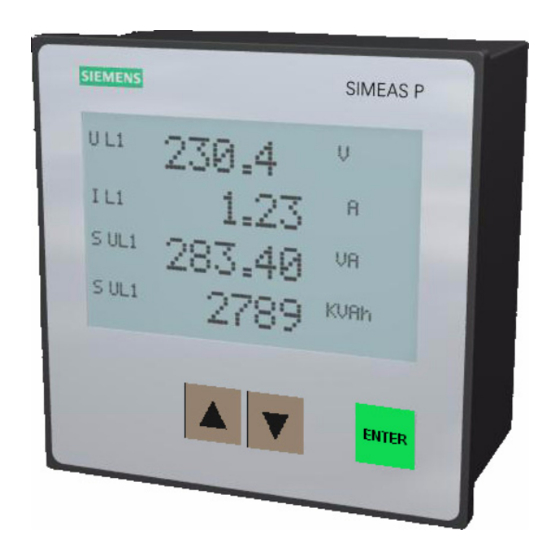
- Page 1 SIMEAS Power Meter 7KG7550/7KG7650/7KG7660 Operating Instructions Order no: E50417-B1076-C263-A5 Edition 07/2004...
-
Page 2: Table Of Contents
Operating Instructions.............2 Compliance ..............2 General Information............3 Qualified Personnel ............5 Ordering Data..............6 Note Concerning Transport ..........7 Range of Application ............7 Mode of Operation............8 Block Diagram ..............9 Measured Values ............11 1.10 Technical Data...............13 1.11 Communication Interface ..........19 1.12 Dimensions ..............20 1.13 Connection Terminals............24 1.13.1 For Devices 7KG7550 and 7KG7650 ......24 1.13.2 For Devices 7KG7660 ..........26 1.14... - Page 3 The warnings and information contained in these operating instructions are provided to ensure personal safety and maximize the useful life of the product. Please follow them! This product is UL-certified to Standard UL 61010B-1, based on the specification stated in Chapter 1.10 (Technical Data). UL File No.: E228586 Measuring Equipment 2UD1...
-
Page 4: Operating Instructions
Voltage Directive 73/23/EEC). Compliance has been verified via testing performed by Siemens AG as per article 10 of the Council Directives in accordance with the generic standards EN 61000-6-4 and EN 61000-6-2 (for EMC Directive) as well as EN 61010-1 (for Low Voltage Directive). -
Page 5: General Information
If more information is required, or if specific problems arise which are not discussed in this document, additional information can be requested from your local Siemens subsidiary or from the address given on the back cover of this document. - Page 6 All commitments of Siemens are specified in the specific purchase contract, which also includes the entire and unique warranty regulations. The contractual warranty regulations are neither extended nor restricted by the information in this document.
-
Page 7: Qualified Personnel
WARNING! During operation of electric devices, certain parts of the device are subject to dangerous voltages. Ignoring the warning notes can result in severe injury or damage to property. Only qualified personnel should be allowed to operate this device. Appropriate transportation, storage, installation and assembly, as well as careful operation and maintenance, are basic requirements for proper and safe operation of this device. -
Page 8: Ordering Data
Ordering Data Description Order-No. Power Meter with grahic-display SIMEAS P500 7KG7 5 5 0 - 0 A A 0 - 0 A A 0 Standard built-in device for control panels 144x144 with graphic display Front protection class IP 41 IP 54 SIMEAS P600 7KG7 6 0 - 0... -
Page 9: Note Concerning Transport
Note Concerning Transport The Lithium-batteries in our equipment are subject to Special Provision 188 of the UN Recommendations on the Transport of Dangerous Goods Model Regulations and Special Provision A45 of the IATA Dangerous Goods Regulation and the ICAO Technical Instructions. This is only valid for the original battery or original spare batteries. -
Page 10: Mode Of Operation
Mode of Operation Input voltages and currents are sampled for calculation of the corresponding r.m.s. values. All measurements derived from sampled values are calculated by a processor. Measured quantities can be displayed on the screens and/or transmitted via the serial interface. With the SIMEAS P, it is possible to program limit value groups for various measured quantities to activate limit violations when the value of a specific measured quantity... -
Page 11: Block Diagram
Block Diagram Basic device: The housing of the RS 485 interface is connected with protective ground (PG). - Page 12 Additional input and output modules are available for the device 7KG7660 (optional): • binary input (2 contacts with common contact) • binary output (2 contacts with common contact) • relay output (3 contacts with common contact) • analog input (2 channels) •...
-
Page 13: Measured Values
Measured Values Measuring Measured values Menu Tolerances path A-N, B-N, ± 0.2% Voltage d a h C-N, (N-G) A-B, B-C, ± 0.2% Voltage d a h C-A, Σ A, B, C, N, ± 0.2% Current d a h Σ Real power P A, B, C, Σ... - Page 14 Measuring Measured values Menu Tolerances path A, B, C, Σ ± 0.5% Reactive power absolute A, B, C, Σ ± 0.5% Apparent power Four-wire ± 0.5% Unbalanced voltage d a h system Four-wire ± 0.5% Unbalanced current d a h system ±...
-
Page 15: Technical Data
1.10 Technical Data Input signals Only for connection to AC systems Max. system voltage 600 V (phase-to-phase) Overload Frequency of fundamental component 40 ... 65 Hz Frequency range f +/- 5 Hz, min. > 30% V Waveform Sinusoidal or distorted up to the 21st harmonic AC current inputs 3 current inputs... - Page 16 Binary outputs Via isolated solid-state relay Permissible voltage 230 V/AC; 250 V/DC Permissible current 100 mA continuous 300 mA for 100 ms 50 Ω Internal resistance Permissible operating 10 Hz frequency Analog outputs (optional, only 7KG7660) Nominal output current 0 to 20 mA DC Output range 0 to 24 mA DC Max.
- Page 17 Auxiliary power Multi-range power supply unit AC /DC Nominal range 24 to 250 V DC or 100 to 230 V AC; 50/60 Hz Total range 7KG7550 and 7KG7650: +/- 20% of nominal range 7KG7660: -10% ... +20% of nominal range DC +/- 20% of nominal range AC Power consumption 7KG7550 and 7KG7650:...
- Page 18 Electromagnetic compatibility Immunity according to IEC 61000-6-2 Emission according to CISPR 11, Class A and 47 CFR, Part 15, Class A Dielectric test, according to IEC 61010-1 routine test, 2 s and UL 61010B-1 Signal inputs mutually (current to current and current to voltage) 2.2 kV;...
- Page 19 Impulse voltage withstand according IEC 60688 and test, test type IEC 60255-5 5 kV; 1.2 / 50 µs All circuits mutually except serial interface Insulation type of inputs and outputs Signal inputs (current) Reinforced, max. 600 V AC, Cat II or max.
- Page 20 Environmental conditions The device is designed for indoor use only Ambient Temperature According to IEC 60688 Operating Temperature Range 32° F to 131° F (0° C to 55° C) Storage Temperature Range -13° F to 158° F (-25° C to 70° C) Max.
-
Page 21: Communication Interface
1.11 Communication Interface Pin-No. RS485-Interface PROFIBUS-Interface Protective Ground Protective Ground B (RxD/TxD-P) CTRL-A +5 V +5 V A (RxD/TxD-N) The bus is terminated at the connection cable. The isolated interface supply voltage is provided via the D-subminiature female connector. Therefore, the matching resistors for signals can be connected to the cable. -
Page 22: Dimensions
1.12 Dimensions IP41 Front NOTE: All dimensions are in mm. Battery slot Width of the device: 144 mm... - Page 24 IP54 Front NOTE: All dimensions in mm. Width of the device: 144 mm...
- Page 25 Housing: Panel flush mounting or cubicle mounting Panel section: 5-7/8" x 5-7/8" (138 x 138 Protection Class: Front IP 41 or IP 54 (refer to ordering data, section 1.4) Terminals Screw-drive terminals for Power supply/PG: Wire size #12-22 AWG Voltage and current inputs: Wire size #12-22 AWG Contact outputs:...
-
Page 26: Connection Terminals
1.13 Connection Terminals 1.13.1 For Devices 7KG7550 and 7KG7650 This device complies with Part 15 of the FCC rules. Operation is subject to the following two conditions: (1) this device may not cause harmful interference, and (2) this device must accept any interference received, including interference that may cause undesired operation. - Page 27 Table 1 Terminal Assignment Terminal Function A phase current, in A phase current, out B phase current, in B phase current, out C phase current, in C phase current, out Phase A voltage input Phase B voltage input Phase C voltage input Neutral Root Common path for output contacts...
-
Page 28: For Devices 7Kg7660
1.13.2 For Devices 7KG7660 This device complies with Part 15 of the FCC rules. Operation is subject to the following two conditions: (1) this device may not cause harmful interference, and (2) this device must accept any interference received, including interference that may cause undesired operation. - Page 29 Table 2 Terminal Assignment Terminal Function A phase current, in A phase current, out B phase current, in B phase current, out C phase current, in C phase current, out Phase A voltage input Phase B voltage input Phase C voltage input Neutral Root Common path for output contacts...
- Page 30 Table 3 I/O modules Ordering Module Code Terminal Allocation Type (refer to section 1.4) equipped BO1+ 2 binary BO2+ outputs n.c. BI1+ 2 binary inputs BI2+ AO1+ AO1- 2 analog AO2+ outputs AO2- AI1+ AI1- 2 analog AI2+ inputs AI2- 3 relays outputs...
-
Page 31: Mounting And Operation
1.14 Mounting and Operation WARNING! During operation of electric devices, certain parts of the device are subject to dangerous voltages. Ignoring the warning notes can result in severe injury or damage to property. Strict compliance with all safety information is imperative. ... -
Page 32: Mounting The Device
1.14.1 Mounting the Device To mount the device, proceed as follows: • Swing the mounting element (provided with the device) over the rear cone. Note: Minimum thickness of the mounting plate: 1 mm; steel... - Page 33 • Move the mounting element to the horizontal position. Use a screw driver 0.6 x 4.5 mm to fix the mounting elements until the slipping clutch takes effect. Note: To prevent accidential contact with energized parts the above described mounting must be taken carefully and correctly.
-
Page 34: Cable Connections
1.15 Cable Connections Listed below is information on making connections to the SIMEAS P, as well as examples of suitable cable types. • Measured quantity input connections (voltage, current): Wire size: #12-22 AWG Cu Min. cable voltage rating min. 600 V AC Solid or stranded with connector sleeve Torque rating: 9 in-lb. -
Page 35: Storage
1.16 Storage During storage, a temperature range between +50°F (10°C) and +95°F (35 °C) is recommended in order to prevent premature aging of components, particularly the electrolytic capacitors. For longer storage periods, it is recommended that voltage be applied to the device power supply for one or two days every other year, in order to regenerate the electrolytic capacitors. - Page 36 WARNING! For field wiring and installation, all national and local codes must be adhered to. During electrical installation, all rules and regulations for power systems must be observed. • If current transformers are used, the secondary connections of the current transformers must be short- circuited before the current leads to the device are interrupted.
-
Page 37: Connection Examples
1.18 Connection Examples The input connections shown below are only examples. Direct connection without the use of current or voltage transformers can be made to the SIMEAS P as long as the maximum allowable current and voltage ratings of the SIMEAS P are not exceeded. - Page 38 Single-phase AC current SIMEAS P Terminals Three-wire three-phase balanced SIMEAS P Terminals...
- Page 39 Three-wire three-phase, unbalanced SIMEAS P Terminals Four-wire three-phase, balanced SIMEAS P Terminals...
- Page 40 Four-wire three-phase, unbalanced (low voltage system) SIMEAS P Terminals Four-wire three-phase, unbalanced (high-voltage system) SIMEAS P Terminals...
-
Page 41: Commissioning
1.19 Commissioning The ratings and information on the nameplate should be checked prior to connecting the power supply voltage. In particular, power supply voltage ratings, as well as input voltage and current ratings should be verified. A warm-up period of 15 minutes is required before the device will perform within specified accuracy limits. - Page 42 After applying voltage to the power supply, the SIMEAS P will run in the startup-phase for 15 seconds. Power Meter S I M E A S - P SIEMENS 7KG7xxx Version: xx.xx.xx...
-
Page 43: Configuration Overview
1.20 Configuration Overview 1.20.1 Operating Notes This chapter describes the basic setting options of the SIMEAS P that are made via the front buttons. ENTER The Main Menu of the programming level can be accessed from the Measured Values screens, the Min-Max Values screens or the Phasor Diagram screen via the "ENTER”... -
Page 44: Window Structure
1.20.3 Window Structure Selecting * and pressing "ENTER" moves the cursor directly to the data entry field on the same line. Selecting > and pressing "ENTER" opens a new window for additional data entry. Selecting < "OK" and pressing "ENTER" confirms the settings and returns the user to the previous level. -
Page 45: Notes
1.20.4 Notes • The selection of the measured quantity depends on the selected input voltage and current connections. • If the number selected is too large, "Overflow" is displayed and the input value is automatically set to the maximum value. •... -
Page 46: Overview Of The Programming Levels: 7Kg7550
Overview of the Programming Levels: 7KG7550 1.20.5 Level 1 corresponds to the measured value screens Levels 2 through 4 correspond to the programming screens and are described as follows: A detailed description of device programming is given in the SIMEAS P Instruction Manual (Order no: E50417-B1076-C210). Level 1 Level 2 Level 3... -
Page 47: 7Kg7650/7Kg7660
1.20.6 Overview of the Programming Levels: 7KG7650/7KG7660 Level 1 Level 2 Level 3 Level 4 main menu screens time/date binary states limit value group oscilloscope basic settings Outputs parameter Interface change code additional settings About SIMEAS Reset screen content configuration I/O modules memory date/time... -
Page 48: Testing And Calibration
1.21 Testing and Calibration WARNING! The following measures must be carried out in compliance with the accident prevention instructions. Appropriate electrical tools must be used. A calibration instrument, which indicates AC voltages, AC currents, and phase angles with an error of ≤ 0.1%, is required for testing and calibrating the Power Quality Recorder. -
Page 49: Maintenance, Repair And Cleaning
1.22 Maintenance, Repair and Cleaning The SIMEAS P does not require special maintenance. If necessary, it can be checked in a laboratory and readjusted. Repair of defective modules is never recommended because specially selected electronic components are used which must be handled in accordance with the procedures required by Electrostatically Endangered Components (EEC). - Page 50 SIEMENS AG. Offenders will be liable for damages. All rights arising from the granting of patents or registration of a design are reserved.
- Page 51 Notes ..........................................................................................................................................................................................................................................................................................
- Page 52 For questions and comments regarding this product please do not hesitate to contact: SIEMENS AG Power Transmission and Distribution Power Automation (PTD PA) Humboldtstraße 59 D-90459 Nürnberg Hotline: Phone: +49 (0)180 524 7000 Fax: +49 (0)180 524 2471 eMail: support@ptd.siemens.com Internet: www.simeas.com...
Need help?
Do you have a question about the SIMEAS P 7KG7550 and is the answer not in the manual?
Questions and answers