Advertisement
Table of Contents
OWNER'S GUIDE & INSTALLATION INSTRUCTIONS
Survey:
Installed in Lloyd's Type-approved Tank, CS235
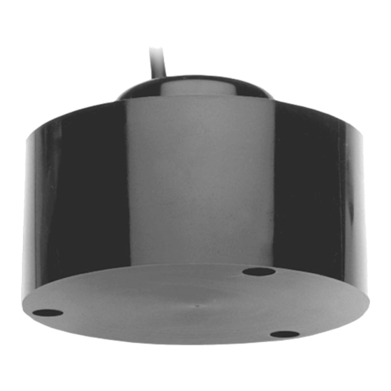
Depth Transducer
Model: M192
Patent http://www.airmar.com/patent.html
Follow the precautions below for optimal product
performance and to reduce the risk of property
damage, personal injury, and/or death.
WARNING: Always wear safety glasses, a dust
mask, and ear protection when installing.
CAUTION: Never pull, carry, or hold the transducer
by the cable as this may sever internal
connections.
CAUTION: Never use solvents. Cleaner, fuel,
sealant, paint, and other products may contain
solvents that can damage plastic parts, especially
the transducer's face.
IMPORTANT: Please read the instructions
completely before proceeding with the installation.
These directions supersede instructions in your
instrument manual if they differ.
Tools & Materials
Safety glasses
Dust mask
Ear protection
Water-based antifouling paint (mandatory in salt water)
Cable gland
Junction box
Underwater lubricant such as Aqualube
Hex wrench: 8M
Marine sealant
NOTE: The terms tank and housing are used interchangeably.
Antifouling Paint
Surfaces exposed to salt water must be coated with antifouling
paint. Paint the housing with an appropriate antifouling, corrosion
inhibiting coating. Use only water-based antifouling paint on the
radiating face of the transducer. Never use ketone-based paint on
the transducer's face since ketones can attack many plastics
possibly damaging the transducer. It is easier to apply antifouling
paint before installation, but allow for sufficient drying time.
Installation
CAUTION: Do not remove the rubber retaining rings.The
transducer's mounting screws utilize rubber retaining rings to hold
the screws in place during installation.
CAUTION: Lubricate the screw threads.Lubrication is necessary
for removing the screws, if the transducer needs to be replaced.
®
Record the information found on the cable tag for future reference.
Part No._________________Date___________Frequency________kHz
cable
passage
cable
stop
cable
loop
connectors
transducer
radiating face
counterbore (3)
Figure 1. Installation
Copyright © 1999 Airmar Technology Corp.
1. Inspect the transducer, cable, and connectors carefully before
installing. All parts must be clean and free of oil, grease, paint,
solvents, and other foreign material that may hinder
performance.
2. Pull the tagged end of the transducer cable (P/N 22-136-01)
through the housing cable passage and the seamless pipe until
the cable stop is seated firmly against the cable passage
opening (Figure 1). Approximately 305mm (12") of cable will
remain in the housing with the male connector attached.
3. Use a suitable cable gland at the top of the pipe to support and
clamp the cable.
4. Secure the free end of the cable in a junction box located in a
dry, gas free environment within the ship.
5. Carefully push the socket head end of each mounting screw
into the counterbore of the transducer to fully expose the
threaded end of the screw. Sparingly apply a uniform coat of
Aqualube
or other similar underwater lubricant to the screw
®
threads.
6. Push the threaded end of each screw back into the transducer
until approximately 7mm (0.25") of the lubricated threads are
exposed and held in place by the retaining ring.
7. While supporting the weight of the transducer, plug the mating
connectors together until they are fully engaged. The connector
faces must touch.
8. Slowly rotate the transducer approximately 1 to 2 turns as it is
raised into the housing to properly dress the cable and joined
connectors in the cable storage cavity. The transducer face will
be almost flush with the flange of the housing when the cable is
properly stowed and the mounting screws are seated in the
threaded holes of the housing.
seamless
pipe
tank
(housing)
cable
storage
cavity
rubber
retaining
ring (3)
mounting
screw (3)
flange
Advertisement
Table of Contents

Subscribe to Our Youtube Channel
Related Manuals for Airmar M192


Summary of Contents for Airmar M192
- Page 1 (3) flange instrument manual if they differ. Figure 1. Installation Copyright © 1999 Airmar Technology Corp. Tools & Materials 1. Inspect the transducer, cable, and connectors carefully before installing. All parts must be clean and free of oil, grease, paint,...
- Page 2 Obtain parts from your instrument manufacturer or marine dealer. Gemeco Tel: 803-693-0777 email: sales@gemeco.com Airmar EMEA Europe, Middle East, Africa Tel: +33.(0)2.23.52.06.48 email: sales@airmar-emea.com 35 Meadowbrook Drive, Milford, New Hampshire 03055-4613, USA • www.airmar.com Copyright © 1999 - 2018 Airmar Technology Corp. All rights reserved.
Need help?
Do you have a question about the M192 and is the answer not in the manual?
Questions and answers