Table of Contents
Advertisement
Quick Links
Network Converter Slave Edition
Applicable product:
Thank you for purchasing an Oriental Motor product.
This Operating Manual describes product handling procedures and safety precautions.
• Please read it thoroughly to ensure safe operation.
• Always keep the manual where it is readily available.
BLV
Series
Table of Contents
1 Setting and connection for BLV Series .............. 2
1.1 Setting of switches for BLV ......................................... 2
2 Using via CC-Link communication .................... 5
2.1 Guidance .................................................................... 5
2.2 Remote register list .................................................... 8
2.3 Assignment for remote I/O ......................................... 8
communications .............................................. 10
3.1 Guidance .................................................................. 10
3.2 I/O field map for the NETC01-M2 ............................ 13
3.3 I/O field map for the NETC01-M3 ............................ 14
3.4 Communication format ............................................. 15
4 Details of remote I/O ....................................... 17
4.1 Remote I/O input (input to BLV) ................................ 17
4.2 Remote I/O output (output from BLV) ....................... 18
5 Command code list ......................................... 19
5.1 Maintenance command ............................................ 19
5.2 Monitor command..................................................... 19
5.3 Operation data.......................................................... 21
5.4 Parameter................................................................. 22
5.5 Group function .......................................................... 26
errors of BLV .................................................... 28
6.1 Alarms ...................................................................... 28
6.2 Warnings .................................................................. 30
6.3 Communication errors .............................................. 31
HP-5065-4
Advertisement
Table of Contents

Subscribe to Our Youtube Channel
Related Manuals for Oriental motor NETC01-CC

Summary of Contents for Oriental motor NETC01-CC
-
Page 1: Table Of Contents
Network Converter Slave Edition Applicable product: Series Thank you for purchasing an Oriental Motor product. This Operating Manual describes product handling procedures and safety precautions. • Please read it thoroughly to ensure safe operation. • Always keep the manual where it is readily available. -
Page 2: Setting And Connection For Blv Series
1 Setting and connection for BLV Series This chapter explains the setting of switches and the connections for when the BLV Series (hereinafter referred to as BLV) is used in combination with the network converter NETC01-CC, NETC01-M2, or NETC01-M3. 1.1 Setting of switches for BLV When the BLV is used with the network converter, set the switches of the BLV driver in advance. -
Page 3: Connection Between Blv And Control Power Supply
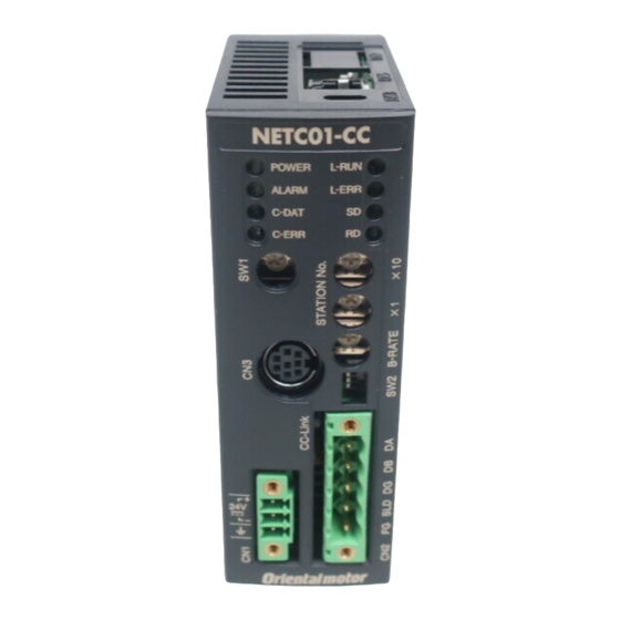
The vacant connector of the BLV driver can be used to connect a different driver. Connect among the drivers using the accessory (sold separately) or commercially RS-485 communication available LAN cable (straight cable). connector of BLV (CN5/CN6) The figure shows the NETC01-CC. −3−... - Page 4 Setting and connection for BLV Series Connector of BLV (CN5/CN6) • Internal circuit C-DAT LED (Green) 6 TR- 3 TR+ 2 GND SW2-No.7 C-ERR LED (Red) 120 Ω 6 TR- 3 TR+ 2 GND 0 V ∗ * The GND line is used in common with main power supply input terminal (CN1) and control power supply input terminal (TB1) [not insulated].
-
Page 5: Using Via Cc-Link Communication
Using via CC-Link communication 2 Using via CC-Link communication Read this chapter when the BLV Series (hereinafter referred to as BLV) is used in combination with the NETC01-CC via CC-Link communication. 2.1 Guidance If you are new to these products, read this section to understand the operating methods along with the operation flow. - Page 6 Green Lit C-ERR LED When C-ERR (red) of the BLV or NETC01-CC is lit: Check the transmission rate or address number of RS-485 communication. When L-ERR (red) of the NETC01-CC is lit: Check the type of the CC-Link communication error.
- Page 7 • Is the C-ERR LED lit? (RS-485 communication error) • Is the L-ERR LED lit? (CC-Link communication error) • Are the parameters of the BLV set correctly? For more detailed settings and functions, refer to the next page and later as well as the NETC01-CC USER MANUAL. −7−...
-
Page 8: Remote Register List
2.2 Remote register list Remote register is common to 6-axes connection mode and 12-axes connection mode. Monitor, read and write of parameters, and maintenance command for the BLV or NETC01-CC are executed using remote register. n is an address assigned to the master station by the CC-Link station number setting. - Page 9 Control input of system area* Status output of system area* RY (n+7) F to RY (n+7) 8 RX (n+7) F to RX (n+7) 8 * Refer to the network converter NETC01-CC USER MANUAL for details. „ Remote I/O input „ ( ): Initial value •...
-
Page 10: Using Via Mechatrolink Communications
Using via MECHATROLINK communications 3 Using via MECHATROLINK communications Read this chapter when the BLV Series (hereinafter referred to as BLV) is used in combination with the NETC01-M2 or NETC01-M3 (hereinafter referred to as NETC01-M2/M3) via MECHATROLINK communications. 3.1 Guidance If you are new to these products, read this section to understand the operating methods along with the operation flow. - Page 11 Using via MECHATROLINK communications STEP 2 Check the connection and the termination resistor. Termination resistor: ON (SW2-No.7) RS-485 communication cable Programmable controller or master device MECHATROLINK- / communication cable ∗2 Termination resistor ∗2 Termination resistor ∗1 NETC01-M2/M3 ∗1 The figure shows the NETC01-M2. ∗2 No termination resistor is required for the NETC01-M3.
- Page 12 Using via MECHATROLINK communications STEP 4 Execute an operation Set the operating speed using the internal potentiometer of the BLV driver. For the NETC01-M2, set the NET-IN3 (FWD) of the address number 0 to ON with the I/O command (DATA_RWA: 50h) of MECHATROLINK-Ⅱ communications to execute an operation. For the NETC01-M3, set the NET-IN3 (FWD) of the address number 0 to ON with the I/O command (DATA_RWA: 20h) of MECHATROLINK-Ⅲ...
-
Page 13: I/O Field Map For The Netc01-M2
Using via MECHATROLINK communications 3.2 I/O field map for the NETC01-M2 Update of remote I/O data (asynchronous) is executed with the “DATA_RWA” command (50h). When the remote I/O occupied size is 16-bit mode and the number of transmission bytes is 32 bytes (initial value), I/O field map will be as follows. -
Page 14: I/O Field Map For The Netc01-M3
Using via MECHATROLINK communications 3.3 I/O field map for the NETC01-M3 Update of remote I/O data (asynchronous) is executed with the “DATA_RWA” command (20h). When the remote I/O occupied size is 16-bit mode and the number of transmission bytes is 32 bytes (initial value), I/O field map will be as follows. -
Page 15: Communication Format
Using via MECHATROLINK communications 3.4 Communication format Communication formats between the BLV and NETC01-M2/M3 are shown below. „ Remote I/O input „ ( ): Initial value • 16 bit mode bit7 bit6 bit5 bit4 bit3 bit2 bit1 bit0 NET-IN7 NET-IN6 NET-IN5 NET-IN4 NET-IN3... - Page 16 Using via MECHATROLINK communications „ Remote register field „ • Command (from NETC01-M2/M3 to BLV) bit 7 bit 6 bit 5 bit 4 bit 3 bit 2 bit 1 bit 0 Command code − TRIG DATA Description Name Description Setting range The command sets the command code for “write and read of parameters, ”...
-
Page 17: Details Of Remote I/O
Details of remote I/O 4 Details of remote I/O This is common to the NETC01-CC, NETC01-M2 and NETC01-M3. 4.1 Remote I/O input (input to BLV) The following input signals can be assigned to the NET-IN0 to NET-IN15 of remote I/O using the parameter. -
Page 18: Remote I/O Output (Output From Blv)
Details of remote I/O 4.2 Remote I/O output (output from BLV) The following output signals can be assigned to the NET-OUT0 to NET-OUT15 of remote I/O using the parameter. Refer to the table below for the assignments of the NET-OUT0 to NET-OUT15. Refer to "I/O function (remote I/O)"... -
Page 19: Command Code List
Command code list 5 Command code list This is common to the NETC01-CC, NETC01-M2 and NETC01-M3. 5.1 Maintenance command These commands are used to clear the alarm history and warning history, and also used to execute the batch processing for the non-volatile memory. - Page 20 Command code list Command Item Description Range code 2056h Present communication error code Monitors the present error code. 2057h Communication error code history 1 2058h Communication error code history 2 2059h Communication error code history 3 205Ah Communication error code history 4 205Bh Communication error code history 5 00h to FFh...
-
Page 21: Operation Data
Command code list 5.3 Operation data There are the following two types of parameters required to operate the motor. • Operation data • User parameters The parameters are saved in the RAM or non-volatile memory. The data saved in the RAM will be erased once the power is turned off. -
Page 22: Parameter
Command code list 5.4 Parameter „ User parameters „ Command code Setting Initial Effective* Item Description Setting range unit value Read Write JOG operating 0 r/min, or 0143h 1143h Sets the rotation speed of JOG operation. speed 80 to 4000 r/min Sets the motor rotation direction to be Motor rotation 0: + direction=CCW... - Page 23 Command code list Operation data setting using analog input signal selection The setting method of operation data can be changed using the analog input signal selection parameter. Combinations of the mode number and analog setting/digital setting are shown below. Only the combinations shown below are available to set.
- Page 24 Command code list „ Alarm/warning „ Command code Setting Effective* Item Description Setting range Initial value unit Read Write 24 VDC Sets the warning level for the specification: 216 Undervoltage warning 0 to 480 01A4h 11A4h undervoltage of the main power (1=0.1 V)...
- Page 25 Command code list „ I/O function (direct I/O) „ Command code Initial value Effective*1 Item Setting range Read Write 0880h 1880h X0 input function selection 0: Not used 20: MB-FREE 1: FWD 21: EXT-ERROR 0881h 1881h X1 input function selection (START/STOP)*2 24: ALARM-RESET 0882h...
-
Page 26: Group Function
Group 0 to 31: Sets a group address.* * Set in a range of 0 to 11 when the NETC01-CC is used, and set in a range of 0 to 15 when NETC01-M2 or NETC01-M3 is used. „ Setting example of group function „... - Page 27 Command code list This is the timing chart for when the FWD was assigned to the NET-IN3 (remote I/O) of the BLV composed the group. Address number 0 Address number 0 Remote I/O input NET-IN3=ON NET-IN3=OFF Motor operation at address number 0 (parent slave) Group setting: –1 Motor operation at...
-
Page 28: Alarms, Warnings And Communication Errors Of Blv
Alarms, warnings and communication errors of BLV 6 Alarms, warnings and communication errors of BLV The BLV provides alarms (protective functions) to protect the BLV from overheating, poor connection, wrong operation and others, as well as warnings (warning functions) to output before the corresponding alarms generate. A communication error will be returned when the processing requested by the master controller could not be executed. - Page 29 Contact your nearest Oriental Motor sales office. • In the case of resetting an alarm with the maintenance command, if an alarm reset is executed in a state where the FWD input or REV input is being ON, it is dangerous because the motor will start rotating after the alarm reset.
-
Page 30: Warnings
Alarms, warnings and communicationerrors of BLV „ Alarm history „ Up to 10 generated alarms are saved in the non-volatile memory in order of the latest to oldest. The stored alarm history can be read or cleared if any of the following items is performed. •... -
Page 31: Communication Errors
Alarms, warnings and communicationerrors of BLV 6.3 Communication errors Up to 10 communication errors are saved in the RAM in order of the latest to the oldest and you can check via RS-485 communication. „ Communication error list „ Communication error Code Cause Remedial action... - Page 32 • Unauthorized reproduction or copying of all or part of this manual is prohibited. If a new copy is required to replace an original manual that has been damaged or lost, please contact your nearest Oriental Motor branch or sales office.
Need help?
Do you have a question about the NETC01-CC and is the answer not in the manual?
Questions and answers