
Related Manuals for HighLine Feed Chopper 1251


Summary of Contents for HighLine Feed Chopper 1251
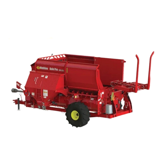
- Page 1 ® Bale Pro Complete Feed Ration ™ Feed Chopper 1251 O p e r a t o r s M a n u a l E16227_A...
- Page 2 The content of this manual was based on the most current information available as of the date of copyright. It is the policy of Highline Manufacturing Limited to improve and develop our products continually. We reserve the right to make changes or add improvements, at any time, without incurring any obligation to make changes or improvements on machines previously sold.
- Page 3 If you find that you require information not covered in this manual, please feel free to consult your local dealer. Your dealer is always able to contact Highline for this technical information. Highline Manufacturing Ltd. thanks and congratulates you for selecting a Feed Chopper for the Complete Feed Ration 1251 as your machine of choice.
-
Page 4: Table Of Contents
Table of Contents General Description of the Feed Chopper Intended Use of the Feed Chopper Section 1 - Safety Serial Number ................1 Safety Sign-off Form . - Page 5 This Page Left Blank...
- Page 6 GENERAL DESCRIPTION OF THE FEED CHOPPER ® The Feed Chopper (FC 1251) is an attachment to the Bale Pro Complete Feed Ration 1251. When the Feed Chopper is engaged, it uses power from the drive of the CFR 1251 to run a belt drive for the Feed Chopper rotor.
- Page 7 This Page Left Blank...
-
Page 8: Serial Number
Section 1 - Safety SERIAL NUMBER Your serial number is found on the serial number plate (1) attached to the Feed Chopper. 219148C Serial Plate Location It is important to record the serial number for proof of ownership and for any service or maintenance assistance. -
Page 9: Safety Sign-Off Form
Highline Manufacturing Ltd. follows the general Safety Standards specified by the American Society of Agricultural Engineers (ASAE) and the Occupational Safety and Health Administration (OSHA). Anyone who will be operating and/or maintaining the Feed Chopper 1251 should read and clearly understand all Safety, Operating and Maintenance information presented in this manual. -
Page 10: Safety Alert Symbol
Section 1 - Safety SAFETY ALERT SYMBOL The Safety Alert Symbol means . . . ATTENTION! BECOME ALERT! YOUR SAFETY IS INVOLVED! The Safety Alert Symbol combined with a Signal Word alert to the presence of a hazard and the degree of possible injury. -
Page 11: General Safety
Section 1 - Safety GENERAL SAFETY 1. Ensure that anyone who is going to operate, maintain or work near the Feed Chopper 1251 is familiar with the recommended operating, maintenance procedures and safety information contained in this manual and follows all the safety precautions. - Page 12 Section 1 - Safety DO NOT CONTACT ROTATING BLADES Rotating blades will cause serious injury or death. Before servicing or adjusting, disengage power take off, shut of the tractor, remove key, set park brake. Before servicing or adjusting, wait for all parts to stop rotating. Keep guards in place and in good condition.
- Page 13 Section 1 - Safety SHUTDOWN THE TRACTOR BEFORE DISMOUNTING TRACTOR Shut down the tractor and remove the key before repairing, servicing, lubricating or cleaning the Feed Chopper. READ, UNDERSTAND AND FOLLOW SAFETY INSTRUCTIONS Read, understand and follow all instructions and safety messages included in this manual and on decals attached to the machine.
-
Page 14: Safety Decal Locations
Section 1 - Safety SAFETY DECAL LOCATIONS 219147 Page 1-7... - Page 15 Section 1 - Safety This Page Left Blank Page 1-8...
-
Page 16: Operating The Feed Chopper
Section 2 - Operating the CFR 1251 Feed Chopper OPERATING THE FEED CHOPPER Operating With the Feed Chopper Shut off the tractor engine and remove the key. Wait for all components to stop rotating. Do not place hands in the Chopper drive clutch area while the flail drum/auger is turning. - Page 17 Section 2 - Operating the CFR 1251 Feed Chopper 1. Put the blower discharge panel into the chopping position. The blower discharge panel (1) can be moved to 3 positions. Moving the panel will move the rear door to direct material into the feed chopper.
- Page 18 Section 2 - Operating the CFR 1251 Feed Chopper 3. Engage the chopper drive clutch. Do not place hands in the Feed Chopper drive clutch area while turning. Contact with the rotating pulley or clutch pin/plate can cause serious injury. Rotate the pulley to align a cutout (1) in the clutch engagement plate with the clutch pin (2).
- Page 19 Section 2 - Operating the CFR 1251 Feed Chopper 5. Begin to process a bale in the CFR 1251. Note: If livestock is being fed, it is the operator's responsibility to ensure that the materials in the processed feed mix are suitable. Some of the wrapping material (twine, net wrap other materials)
-
Page 20: Operating Without The Feed Chopper
Section 2 - Operating the CFR 1251 Feed Chopper Operating Without the Feed Chopper For Bedding 1. Pull the rear door pin (1) to allow the rear door (2) to cover the chopper. This door position will cause the material to by pass over the chopper and be discharged. - Page 21 Section 2 - Operating the CFR 1251 Feed Chopper For Feeding Without Chopping To place feed in a windrow or a bunk, raise the discharge panel to the highest position. Place the blower discharge panel (1) into one of the upper slots (2) of the arc for the greater lift.
-
Page 22: Unplugging The Feed Chopper
Section 2 - Operating the CFR 1251 Feed Chopper Unplugging the Feed Chopper 1. Reduce the engine speed to idle. 2. Disengage tractor power take off (PTO). 3. Set the tractor park brake. Shut off tractor engine and remove the key. Wait for all components to stop rotating. - Page 23 Section 2 - Operating the CFR 1251 Feed Chopper 5. Clear the chopping area and the knives. Wait for all components to stop rotating. Do not place hands in the Feed Chopper while the rotor is turning. Contact with the rotating knives will cause serious injury.
- Page 24 Section 2 - Operating the CFR 1251 Feed Chopper 8. Replace the cover and door. Push the discharge door back to move the hinge towards the back of the slot. Pull the on the rear door pin lock (3) to compress the spring to allow the pin to enter the slot on the rear door.
- Page 25 Section 2 - Operating the CFR 1251 Feed Chopper This Page Left Blank Page 2-10...
-
Page 26: Maintaining The Feed Chopper
Section 3 - Maintaining the Feed Chopper MAINTAINING THE FEED CHOPPER Lubrication Lubricate all grease fittings with a quality lithium complex, extreme pressure NLGI Grade 2 grease. Every 10 Hours ! Lubricate 1 point on the chopper rotor front bearing. Open the chopper drive shield to access the front grease point. -
Page 27: Rotor Knife Replacement
Section 3 - Maintaining the Feed Chopper Rotor Knife Replacement Replace knives that are broken or worn to the point that they will not process material properly. Four knives must be replaced at the same time. Note: To maintain rotary balance, the set of knives on the opposite side of the rotor must be replaced at the same time. -
Page 28: Replacing The Chopper Drive Belt
Section 3 - Maintaining the Feed Chopper Replacing the Chopper Drive Belt Removing the Drive Belt 1. Disconnect and remove the driveline (1) for ease in changing the belt. 2. Open the drive shield on the left side (2) of the machine. Leave this shield attached. - Page 29 Section 3 - Maintaining the Feed Chopper 5. Loosen the chopper belt tensioner (6) located below the drive box. To loosen the belt tensioner: 219128C2 Loosen the Feed Chopper Tensioner (If present) Loosen the jam nut (1) on the threaded rod. Turn the nut (2) next to the spring washer to remove the tension on the spring.
- Page 30 Section 3 - Maintaining the Feed Chopper 7. Remove the nuts (3) holding the gearbox support frame to the hitch. Keep the bolt and nuts for re-use. 8. Move the chopper drive belt to be around the base of the gearbox support. 9.
- Page 31 Section 3 - Maintaining the Feed Chopper 5. Place the bolts up through the hitch and tubes and fasten with the nuts (3). Torque to 295 lbf (400 Nm). 219129C Fasten the Gearbox Support Frame 6. Tighten the feed chopper belt tension. To adjust feed chopper belt tension: Turn the nut (2) next to the spring washer (3) to adjust the spring so...
- Page 32 Section 3 - Maintaining the Feed Chopper To adjust flail/auger belt tension: Turn the nut (4) next to the spring washer (1) to adjust the spring so it shows in the cut out window (2). Tighten the jam nut (3) on the threaded rod.
-
Page 33: Rotor Twine Scraper Adjustment
Section 3 - Maintaining the Feed Chopper Rotor Twine Scraper Adjustment Adjust the twine scrapers (3) on both ends of the rotor shaft. Loosen the bearing bolt nuts (4) that have the twine scraper on it to allow the bearing bolts to be loose. Slide the twine scraper (3) on the bearing bolts until it is almost touching the rotor shaft. -
Page 34: Troubleshooting
Replace knives as pairs and also replace knife pair on opposite side of rotor to maintain rotational balance. Check for damage to the rotor. Contact Highline for proper repair procedure. Failed rotor end bearing. Check if rotor rotation feels rough. Replace failed bearing. - Page 35 Section 4 - Troubleshooting Symptom Problem Solution Rotor Does Not Spin Drive clutch is not engaged. Move the clutch engage pin to the Engaged Position. Ensure the drive pin is locked in position. Broken Drive Belt. Replace the belt. Foreign material lodged in Remove foreign material to housing.
- Page 36 (1) full year after initial purchase/retail sale. Highline will warrant its product for one (1) year parts and labour, if performed by a qualified Dealer. This Limited Warranty shall apply only to complete machines of Highline's manufacture. Parts are covered by a separate Limited Warranty.
- Page 37 12. Depreciation damage caused by normal wear, lack of reasonable and proper maintenance, failure to follow operating instructions, misuse, and/or lack of proper protection during storage. 13. Accessory systems and electronics not of Highline's manufacture are warranted only to the extent of such manufacturer's respective Limited Warranty if any.
Need help?
Do you have a question about the Feed Chopper 1251 and is the answer not in the manual?
Questions and answers