Table of Contents
Advertisement
Advertisement
Table of Contents

Related Manuals for HighLine Bale Pro CFR651


Summary of Contents for HighLine Bale Pro CFR651
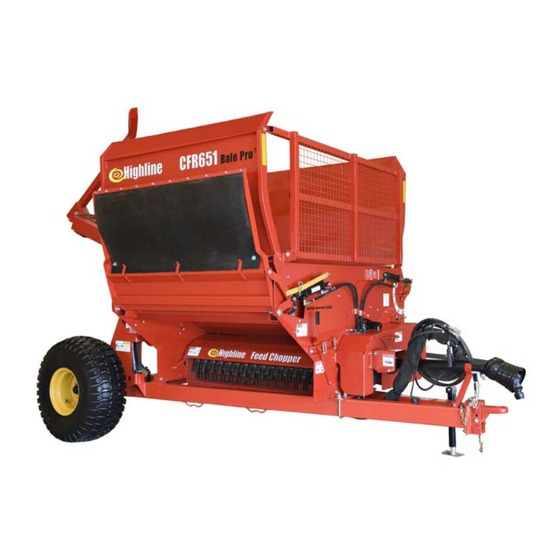
- Page 1 ® Bale Pro Complete Feed Ration CFR651 O p e r a t o r s M a n u a l E12033V3_A...
- Page 2 The content of this manual was based on the most current information available as of the date of copyright. It is the policy of Highline Manufacturing Limited to improve and develop our products continually. We reserve the right to make changes or add improvements, at any time, without incurring any obligation to make changes or improvements on machines previously sold.
- Page 3 If you find that you require information not covered in this manual, please feel free to consult your local dealer. Your dealer is always able to contact Highline for this technical information. Highline Manufacturing Ltd. thanks and congratulates you for selecting a Complete Feed Ration 651 as your machine of choice.
-
Page 4: Table Of Contents
Table of Contents Section 1 - Safety Serial Number ......1 Safety Decals ....... . . 4 Safety Sign-off Form . - Page 5 Section 6 - Storing the CFR 651 Clean all the debris from the tub area ... 1 Disconnect the safety chain ..... . 4 Park the CFR 651 on level ground .
- Page 6 GENERAL DESCRIPTION OF THE COMPLETE FEED RATION 651 (CFR 651) The Complete Feed Ration 651 (CFR 651) is a machine to process round bales of hay or other animal feed materials. When the CFR 651 is engaged, it uses power from the tractor PTO to rotate a flail drum.
- Page 7 This Page Left Blank...
-
Page 8: Serial Number
Section 1 - Safety SERIAL NUMBER Your serial number is found on the serial number plate attached to the tub wall of the Complete Feed Ration 651. 215120C Serial Plate Location It is important to record the serial number for proof of ownership and for any service or maintenance assistance. -
Page 9: Safety Sign-Off Form
Section 1 - Safety SAFETY SIGN-OFF FORM Highline Manufacturing Ltd. follows the general Safety Standards specified by the American Society of Agricultural Engineers (ASAE) and the Occupational Safety and Health Administration (OSHA). Anyone who will be operating and/or maintaining this equipment should read and clearly understand all Safety, Operating and Maintenance information presented in this manual. -
Page 10: Safety Alert Symbol
Section 1 - Safety SAFETY ALERT SYMBOL The Safety Alert Symbol means: ATTENTION! BECOME ALERT! YOUR SAFETY IS INVOLVED! The Safety Alert Symbol combined with a Signal Word alert to the presence of a hazard and the degree of possible injury. Indicates an imminently hazardous situation that, if not avoided, WILL result in DEATH OR SERIOUS INJURY. -
Page 11: General Safety
3. Replaced parts that displayed a decal should also display the current decal. 4. Decals are available from the Highline Parts Department. 5. Be familiar with the decals, the type of warning and the area or function(s) related to the area(s) that requires your awareness. - Page 12 Section 1 - Safety DO NOT CONTACT ROTATING DRIVELINE Contact with rotating driveline will cause serious injury or death. Keep all driveline guards in place. Securely attach drivelines at both ends. Check that the driveline guards turn freely on the driveline. DO NOT OPERATE WITH SHIELDS MISSING Stop engine and ensure the PTO driveline is stopped before working on driveline...
- Page 13 Section 1 - Safety STAY AWAY FROM OVERHEAD POWER LINES Stay away from overhead power lines when transporting equipment. Serious injury or death from electrocution can occur without contacting power lines. STAY BACK FROM AN OPERATING MACHINE WHICH CAN DISCHARGE OBJECTS SEVERAL FEET Stay clear from discharge side when PTO is engaged.
- Page 14 Section 1 - Safety DO NOT RIDE ON MACHINE Falling from the moving machine can cause serious injury or death. Falling from the operating machine can cause being entangled under the machine or being injured by the machine. READ, UNDERSTAND, AND FOLLOW SAFETY INSTRUCTIONS Read, understand and follow all instructions and safety messages included in this manual and on decals attached to the machine.
- Page 15 Section 1 - Safety INSTALL CYLINDER LOCK BEFORE GOING UNDER RAISED BALE FORKS Install and secure the cylinder lock before going under raised bale forks. Install and secure cylinder lock before using the twine cutter. USE PAPER OR CARDBOARD TO CHECK FOR HYDRAULIC LEAKS To prevent serious injury or death: Relieve pressure on hydraulic system before repairing, adjusting or...
- Page 16 Section 1 - Safety DO NOT EXCEED 80 TURNS IN OPERATION Do not operate the Constant Velocity (CV) driveline at greater than to prevent damage to the driveline. KEEP AXLE U-BOLTS TIGHT axles could slide out of the frame if the u-bolts are loose. This may result in injury/ Tighten u-bolts after first 5 hours of use.
- Page 17 Section 1 - Safety SAFETY DECAL LOCATIONS 216197 Page 1-10...
-
Page 18: Transporting The Cfr
Section 2 - Transporting the CFR 651 2.0 TRANSPORTING THE CFR 651 Only tow the CFR 651 behind a properly sized and equipped tractor which exceeds the loaded weight of the CFR 651 by 50%. Do not tow behind a truck or other type of vehicle. -
Page 19: Tractor Requirements
Section 2 - Transporting the CFR 651 1. Tractor Requirements Roll Over Protection System (ROPS) Working seatbelts 1 3/8" 21 spline PTO PTO requirement refer "Specifications" Section for the PTO requirements. 3 Selective Control Valves (SCV) An optional solenoid valve is available for tractors with 2 SCV. -
Page 20: Lift The Hitch
Section 2 - Transporting the CFR 651 4. Lift the hitch. Lift the Hitch with the jack (1). The hitch is heavy. Do not attempt to lift it without using the jack. 5. Connect the hitch to the tractor clevis drawbar. -
Page 21: Attach Driveline To Pto
Section 2 - Transporting the CFR 651 8. Attach driveline to PTO. Note: Use the Category 6 drive line with the Feed Chopper Option. Shut off the tractor engine before a t t a c h i n g P T O d r i v e l i n e . -
Page 22: Attach Hydraulics
Section 2 - Transporting the CFR 651 9. Attach hydraulics. Clean the end of the hoses and the connection. Firmly push the hoses into the tractor receptacle according user preference. Route the hoses so they do not interfere with moving parts. 201199 Attach Hydraulics Connect the lights. - Page 23 Section 2 - Transporting the CFR 651 Adjust wheel stance settings. Increase the wheel stance to maintain stability when working on hilly terrain or rough ground. Note: Ensure the bale processing tub is empty before adjusting wheel stance. Jack up the main axle under the cylinder mount and support.
- Page 24 Section 2 - Transporting the CFR 651 Raise the bale loading forks to the highest position. Install the cylinder lock (1) on the cylinder of the bale loading forks. Fasten the cylinder lock in place with the pin (2). Raise the discharge deflector door to the transport position.
- Page 25 Section 2 - Transporting the CFR 651 Ensure that the Slow Moving Vehicle (SMV) sign is clean and visible. 216192 Ensure SMV is Visible Transport Do not transport on public roads with bales in the processor tub. Do not transport on public roads with a bale loaded on the forks.
-
Page 26: Preparing The Cfr
Section 3 - Preparing the CFR 651 3.0 PREPARING THE CFR 651 Check these items each time before using the machine. 1. Park the tractor and CFR 651 on level ground. Engage the tractor parking brake and shut down the tractor. 2. -
Page 27: Check The Condition Of The Flails
Section 3 - Preparing the CFR 651 5. Clean debris and material buildup from the flail drum area and the processor tub. Do not use the twine cutter tool to dislodge jammed material. Check the condition of the drum. 6. Check the condition of the flails. 212043 Clean Debris and Check Drum and Flails Spin the drum by hand to check all the... -
Page 28: Check The Condition Of The Feeder Chain
Section 3 - Preparing the CFR 651 8. Check the condition of the feeder chain. Remove any debris in the tub area that would interfere with the operation of the feeder chain. Remove any twine or netwrap caught in the feeder chain bars. Remove any twine or netwrap caught in the chain. -
Page 29: Adjust The Height Of The Hitch Tongue
Section 3 - Preparing the CFR 651 Adjust the height of the hitch tongue. Note: Do this procedure on level ground. Level the frame of the CFR 651 to ensure the bale forks can be lowered to load a bale. Adjust the hitch tongue height to connect with the tractor drawbar while keeping the frame level . -
Page 30: Verify The Position Of The Lower Discharge Door
Section 3 - Preparing the CFR 651 Verify the position of the lower discharge door (4). Look under the tub at the discharge area to verify the position of the lower discharge door (4). 212047C Verify Position of Lower Discharge Door Remove any material that has built up around the feeder chain bearings. - Page 31 Section 3 - Preparing the CFR 651 Check the condition and tension of the flail drum drive belt. Release the belt drive shield and swing out of the way. Check the condition of the drive belt. Check the tension of the drive belt. The tensioner should be set to the 25 degree mark.
- Page 32 Section 3 - Preparing the CFR 651 Adjust the bale loader forks for the width of bale being processed. For bales 6 feet (1.8 m) in diameter Place both fork inner u-bolts against the brace (1). 201209C Fork Width - 6 Foot (1.8m) Bales For bales 5 feet (1.5 m) in diameter Place both fork outer u-bolts against the inside of the brace (2).
- Page 33 Section 3 - Preparing the CFR 651 Inspect all the hydraulic motors, cylinders and hoses. Use a piece of cardboard or heavy paper to check for leaks. Do not use your hand. Wear proper hand and eye protection when searching for leaks. Relieve pressure on hydraulic system before repairing, adjusting or disconnecting.
- Page 34 Section 3 - Preparing the CFR 651 Check that the axle u-bolts (1) are tight. Torque the axle u-bolts (1) to 250 lbf (339 Nm) to ensure the axles do not slide out of the frame. Maximum axle extension is 14" (355 mm) from the main tube edge to the inside face of the spindle plate.
- Page 35 Section 3 - Preparing the CFR 651 Remove the flail drum lock pin from the tube (1) on the flail drum plate. Note: Failure to unlock the flail drum will result in damage to the machine during start up. 213179C Disengage the Flail Drum Lock Place the drum lock pin into the storage holder on the outside of...
- Page 36 Section 3 - Preparing the CFR 651 Note: If the Feed Chopper is installed, the cylinder lock is to be stored in the hole of the tub end wall. 212067 Cylinder Lock Stored (With Feedchopper) Note: If the Grain Tank is installed, the cylinder lock is to be stored in the hole in the Grain Tank support.
- Page 37 Section 3 - Preparing the CFR 651 Remove the clip pin and lock pin on the discharge deflector door to allow the door to be operated by the hydraulic cylinder. Note: The cylinder may need to be moved with the hydraulics to remove the weight of the door from the lock.
- Page 38 Section 3 - Preparing the CFR 651 NetWrap or Twine Removal Procedure Remove netwrap or twine that is around the flail drum. Note: Remove the twine from the flail drum and feed rollers every 25 bales. Premature bearing failure can occur if twine is allowed to build up on the flail drum.
- Page 39 Section 3 - Preparing the CFR 651 3. At the front of the machine, move the flail guard rod adjustment lever to a number between 1 and 4. Note: Having the lever at position 5 will result in damage to the twine cutter blade.
- Page 40 Section 3 - Preparing the CFR 651 8. Move any flails blocking the knife path. Reach through the drum access panels and move any flails that are lying across the knife path. Failure to move flails on the knife path will result in damage to the twine cutter blade.
-
Page 41: Unlock The Flail Drum
Section 3 - Preparing the CFR 651 Place twine cutter back into the storage position. Ensure the handle is facing down and is locked into the key hole slot. 212070 Replace Twine Cutter Into Storage Position Unlock the flail drum. Remove the drum lock pin from the flail drum drive plate tube (1). - Page 42 Section 3 - Preparing the CFR 651 Remove the netwrap or twine from the flail drum. 212043 Remove Netwrap & Twine Replace the flail drum access panels. Fasten in place with the panel pins (1). Secure with the clip pins. 213177C Replace the Flail Drum Access Panels Remove the fork lock from the...
- Page 43 Section 3 - Preparing the CFR 651 This Page Left Blank Page 3-18...
- Page 44 Section 4 - Operating the CFR 651 OPERATING THE CFR 651 Do not allow anyone to ride on the CFR 651. Falling from the machine can cause injury Do not enter the tub while parts are rotating. With Bale in Tub Without Bale in Tub The bale is unstable and may cause entrapment.
-
Page 45: Set The Aggression Level Of The Flails
Section 4 - Operating the CFR 651 Discharge Rate Settings There are 2 settings that determine the discharge rate of material and the time it takes to process a bale: ! The aggression level of the flails acting on the bale. ! The speed of the feeder chain which feeds the bale into the flail drum. -
Page 46: Set The Speed Of The Feeder Chain
Section 4 - Operating the CFR 651 2. Set the speed of the feeder chain. Set the direction of the feeder chain so that the chain bars move toward the flail drum. This will keep the bale against the flails and rotate the bale. It will also cause the bottom of the bale to move against the flail guard rods. -
Page 47: Set The Upper Deflector Door
Section 4 - Operating the CFR 651 3. Set the upper deflector door. Raise or lower the upper deflector door adjust amount spreading of material. Use the hydraulic cylinder to adjust the door. Note: If the 2 remote option is installed, the door cylinder will be linked to the bale lift hydraulic circuit through an electric solenoid... -
Page 48: Set The Level Of Lower Discharge Door
Section 4 - Operating the CFR 651 4. Set the level of the lower discharge door. (No Feed Chopper Present) The lower discharge door adjustment handle (1) is located on the rear tub wall. There are 3 door positions: The lowest position is often used for wet material or for a shorter 213182C Lower Discharge Door... -
Page 49: Load The Bale Into The Processor Tub
Section 4 - Operating the CFR 651 5. Load the bale into the processor tub. Align the center of a bale with the center of the processor. Lower the forks completely. Slowly back up to the bale until the forks are completely under the bale. Raise the forks enough to lift the bale off the ground. -
Page 50: Load A Second Bale
Section 4 - Operating the CFR 651 6. Lower the forks and load a second bale (optional). Another bale may be loaded onto the forks while a bale is in the processor. If a bale is loaded onto the forks, raise the forks as high as possible. - Page 51 Section 4 - Operating the CFR 651 8. Begin processing material. Start the feeder chain to move the bale towards the flail drum. Note: If processor vibrates e x c e s s i v e l y , i m m e d i a t e l y disengage PTO and stop the tractor.
- Page 52 Section 4 - Operating the CFR 651 Adjust aggression level needed). If the different rate of material discharge is desired: Stop the tractor and remove the key. Wait until all flail drum rotation has stopped. Move the discharge rate lever. 213021 Adjust Aggression Level Higher...
- Page 53 Section 4 - Operating the CFR 651 Crossing ditches and steep inclines. Cross ditches or inclines at about a 30° approach angle. 107072 Cross Ditch at 30° Angle Do not approach a ditch or steep incline straight on as this may collapse the driveline to its shortest length, causing damage by pushing the PTO into the tractor or into the drivebox or...
-
Page 54: Maintaining The Cfr
Section 5 - Maintaining the CFR 651 MAINTAINING THE CFR 651 Shut down the tractor and remove the key before repairing, servicing, lubricating cleaning machine. Relieve all hydraulic pressure in hoses. Disconnect hydraulic hoses from the tractor before going near the machine. Lubrication Lubricate all grease fittings with a quality lithium complex, extreme pressure NLGI... - Page 55 Section 5 - Maintaining the CFR 651 ! Lubricate 1 point on the front flail drum bearing. 213185C Lubricate the Driveline Sheave Bearing ! Lubricate 2 points on the upper feeder chain bearings One the front tub wall and one on the back tub wall.
-
Page 56: Visually Inspect Hydraulic Hoses/Fittings
Section 5 - Maintaining the CFR 651 ! Lubricate 1 point on the lower feeder chain bearing on the inside front of the tub. This bearing is connected to the hydraulic feeder chain motor. 212073C Grease Lower Chain Bearing (Inside Tub) Every 100 Hours ! Hubs on spindles - Lubricate the hubs every 100 hours. -
Page 57: Adjust The Feeder Chain Tension
Section 5 - Maintaining the CFR 651 Adjust the Feeder Chain Tension Loosen the bolts on the front and rear upper feeder chain bearings (1). Loosen the jam nut (2) on front and rear adjustment bolt. Turn the adjustment nut (3) to change the chain tension. -
Page 58: Adjust The Belt Tension For The Flail Drum Drive
Section 5 - Maintaining the CFR 651 Adjust the Belt Tension for the Flail Drum Drive The belt tension adjuster will adjust to keep the belt tight within a range of tension. The tensioner should be set to a tension of 25 degrees. - Page 59 Section 5 - Maintaining the CFR 651 To get more adjustability from the tensioner, move the anti-rotation bolt. Loosen the top nut (1). Place a socket wrench onto the nut (3) on the tension adjustment arm. Take up the tension of the belt when lower loosened.
-
Page 60: Changing The Gearbox To Flail Drum Belt
Section 5 - Maintaining the CFR 651 Changing the Gearbox to Flail Drum Belt The alignment of the drivebox belt sheave to the flail drum belt sheave is an important adjustment that is set at the factory. To maintain this setting when changing the flail drum drive belt, the drive box is mounted on a hinged mount. - Page 61 Section 5 - Maintaining the CFR 651 7. Route the belt onto the drivebox sheave, flail drum sheave and the tensioner. 8. Replace the drivebox mount bolts (1) and fasten with the locknuts. 9. Adjust the tension on the belt by following the instructions above.
-
Page 62: Gearbox Oil Changing Procedures
Section 5 - Maintaining the CFR 651 Gearbox Oil Changing Procedures Change the oil annually and before storing the CFR 651 for the season. Before beginning, make sure the tractor is off and the PTO is disengaged. Disconnect driveline from the tractor before doing any work. -
Page 63: Flail Replacement Procedure
Section 5 - Maintaining the CFR 651 Flail Replacement Procedure Replace flails that are broken or worn to the point that they will not process material properly. Before beginning, make sure the tractor is off and the PTO is disengaged. Disconnect driveline from the tractor before doing any work. -
Page 64: Tires
Section 5 - Maintaining the CFR 651 Tires Note: It is recommended to have the tires mounted by a tire technician. Check the condition of the tires. Mount the rim so that the air valve will be facing outward when mounted on the CFR 651. - Page 65 Section 5 - Maintaining the CFR 651 ! Remove any twine that is built up around the axle spindle and hub. Be careful to not damage the grease seal on the bearing while removing twine. 212021 Remove Twine From the Spindle and Hub Page 5-12...
-
Page 66: Storing The Cfr
Section 6 - Storing the CFR 651 STORING THE CFR 651 Instructions for storing longer than a week: 1. Clean all the debris from the tub area and off the CFR 651. 2. Park the CFR 651 on level ground. 3. -
Page 67: Lock The Cfr 651 Flail Drum
Section 6 - Storing the CFR 651 5. Lock the CFR 651 flail drum. Place the flail drum lock pin into the tube on the front tub wall. Allow the lock pin to slid into the processing chamber. Manually rotate the flail drum until the lock pin drops into place locking the flail drum. -
Page 68: Lower The Forks To The Ground
Section 6 - Storing the CFR 651 7. Lower the forks to the ground. Fasten the fork lock in the storage position. 8. Raise the discharge deflector door to the transport position. The top discharge deflector door is operated by a hydraulic cylinder. 215126 Lower Forks to the Ground Note: If the 2 remote option is... -
Page 69: Place The Jack Onto The Hitch
Section 6 - Storing the CFR 651 Place the jack onto the hitch. Remove the jack from the storage position. Pin the jack in place on the hitch. Ensure that the jack is resting on solid level ground or resting on a wood block. -
Page 70: Secure The Hydraulic Hoses And Electrical Connector To The Hose Holder
Section 6 - Storing the CFR 651 Secure the hydraulic hoses and electrical connector to the hose holder on the hitch to keep them off the ground and clean. Place the driveline into the driveline support. 216114 Hoses and Driveline in Supports Change the oil in the gearbox. - Page 71 Section 6 - Storing the CFR 651 This Page Left Blank Page 6-6...
- Page 72 Section 7 - Troubleshooting TROUBLESHOOTING Symptom Problem Solution Bale lifting problems Forks do not raise Check hydraulic connections and lines Electric solenoid valve (if Check the electrical present) connection to the solenoid Check that hydraulic fluid passes through the solenoid valve Bale tips off back of forks Narrow forks for a better lift...
- Page 73 Section 7 - Troubleshooting Symptom Problem Solution Difficult to rotate bale in tub Feeder chain not fully Increase aggression of flails engaging bale to help rotate bale Direct feeder chain to move the bottom of the bale toward the flail drum Bale on forks contacting Lower the bale on the forks bale in tub...
- Page 74 Section 8 - Specifications CFR 651 SPECIFICATIONS Width Base CFR Width 101 5/8"" (2581 mm) CFR With Feed Chopper 112 1/2" (2857 mm) CFR With MGIS 137 5/8" (3495 mm) CFR With Feed Chopper and MGIS 137 5/8" (3495 mm) Overall Length (To end of tires) 173 3/4"...
- Page 75 Section 8 - Specifications Tires 16.5LX 16.1 ANS (Inflate to 24 psi) Gearbox Oil Capacity 300 ml Page 8-2...
- Page 76 (1) full year after initial purchase/retail sale. Highline will warrant its product for one (1) year parts and labour, if performed by a qualified Dealer. This Limited Warranty shall apply only to complete machines of Highline's manufacture. Parts are covered by a separate Limited Warranty.
- Page 77 12. Depreciation damage caused by normal wear, lack of reasonable and proper maintenance, failure to follow operating instructions, misuse, and/or lack of proper protection during storage. 13. Accessory systems and electronics not of Highline's manufacture are warranted only to the extent of such manufacturer's respective Limited Warranty if any.
Need help?
Do you have a question about the Bale Pro CFR651 and is the answer not in the manual?
Questions and answers