Table of Contents
Advertisement
Advertisement
Table of Contents

Related Manuals for HighLine Bale Pro CFR650


Summary of Contents for HighLine Bale Pro CFR650
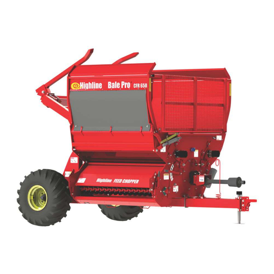
- Page 1 ® Bale Pro Complete Feed Ration CFR650 O p e r a t o r s M a n u a l E9813V1...
- Page 2 The content of this manual was based on the most current information available as of the date of copyright. It is the policy of Highline Manufacturing Limited to improve and develop our products continually. We reserve the right to make changes or add improvements, at any time, without incurring any obligation to make changes or improvements on machines previously sold.
- Page 3 If you find that you require information not covered in this manual, please feel free to consult your local dealer. Your dealer is always able to contact Highline for this technical information. Highline Manufacturing Ltd. thanks and congratulates you for selecting a Complete Feed Ration 650 as your machine of choice.
-
Page 4: Table Of Contents
Table of Contents Page Section 1 - Safety Serial number ................1 Safety sign-off form . - Page 5 Section 6 - Storing the CFR 650 Clean all the debris ......1 Install the discharge deflector door transport lock ..2 Park the CFR 650 on level ground .
- Page 6 GENERAL DESCRIPTION OF THE COMPLETE FEED RATION 650 (CFR 650) The Complete Feed Ration 650 (CFR 650) is a machine to process round bales of hay or other animal feed materials. When the CFR 650 is engaged, it uses power from the tractor PTO to rotate a flail drum.
- Page 7 This Page Left Blank...
-
Page 8: Serial Number
Section 1 - Safety SERIAL NUMBER Your serial number is found on the serial number plate (1) attached to the Complete Feed Ration 650 on the top left hand side of the front tub wall. 215068C Serial Plate Location It is important to record the serial number for proof of ownership and for any service or maintenance assistance. -
Page 9: Safety Sign-Off Form
Section 1 - Safety SAFETY SIGN-OFF FORM Highline Manufacturing Ltd. follows the general Safety Standards specified by the American Society of Agricultural Engineers (ASAE) and the Occupational Safety and Health Administration (OSHA). Anyone who will be operating and/or maintaining the Complete Feed Ration 650 should read and clearly understand all Safety, Operating and Maintenance information presented in this manual. -
Page 10: Safety Alert Symbol
Section 1 - Safety SAFETY ALERT SYMBOL The Safety Alert Symbol means: ATTENTION! BECOME ALERT! YOUR SAFETY IS INVOLVED! The Safety Alert Symbol combined with a Signal Word alert to the presence of a hazard and the degree of possible injury. Indicates an imminently hazardous situation that, if not avoided, WILL result in DEATH OR SERIOUS INJURY. -
Page 11: General Safety
3. Replaced parts that displayed a decal should also display the current decal. 4. Decals are available from the Highline Parts Department. 5. Be familiar with the decals, the type of warning and the area or function(s) related to the area(s) that requires your awareness. - Page 12 Section 1 - Safety DO NOT CONTACT ROTATING DRIVELINE Contact with rotating driveline will cause serious injury or death. Keep all driveline guards in place. Securely attach drivelines at both ends. Check that the driveline guards turn freely on the driveline. DO NOT OPERATE WITH SHIELDS MISSING Stop engine and ensure the PTO driveline is stopped before working on driveline...
- Page 13 Section 1 - Safety STAY AWAY FROM OVERHEAD POWER LINES Stay away from overhead power lines when transporting equipment. Serious injury or death from electrocution can occur without contacting power lines. STAY BACK FROM AN OPERATING MACHINE WHICH CAN DISCHARGE OBJECTS SEVERAL FEET Stay clear from discharge side when PTO is engaged.
- Page 14 Section 1 - Safety READ, UNDERSTAND, AND FOLLOW SAFETY INSTRUCTIONS Read, understand and follow all instructions and safety messages included in this manual and on decals attached to the machine. These instructions and safety messages contain important information. Allow only responsible, properly instructed individuals to operate and service the machine.
- Page 15 Section 1 - Safety USE PAPER OR CARDBOARD TO CHECK FOR HYDRAULIC LEAKS To prevent serious injury or death: Relieve pressure on hydraulic system before repairing, adjusting or disconnecting. Wear proper hand and eye protection when searching for leaks. Use wood or cardboard instead of hands. Keep all components in good repair.
- Page 16 Section 1 - Safety SHUT DOWN TRACTOR BEFORE USING TWINE CUTTER Use the shutdown procedure to ensure no movement of the flail drum will occur while cutting twine or netwrap. LOCK FORKS AND FLAIL DRUM BEFORE USING TWINE CUTTER Lock forks in the upright position before going under the raised forks.
-
Page 17: Safety Decal Locations
Section 1 - Safety SAFETY DECAL LOCATIONS 650DecalIso2 Page 1-10... -
Page 18: Transporting The Cfr 650
Section 2 - Transporting the CFR 650 2.0 TRANSPORTING THE CFR 650 Only tow the CFR 650 behind a properly sized and equipped tractor which exceeds the loaded weight of the CFR 650 by 50%. Do not tow behind a truck or other type of vehicle. -
Page 19: Tractor Requirements
Section 2 - Transporting the CFR 650 1. Tractor Requirements Roll Over Protection System (ROPS) Working seatbelts 1 3/8" 21 spline PTO PTO requirement refer “Specifications” Section for the PTO requirements. 3 Spool Control Valves (SCV) An optional solenoid valve is available for tractors with 2 SCV. -
Page 20: Lift The Hitch
Section 2 - Transporting the CFR 650 4. Lift the hitch. Lift the Hitch with the jack (1) The hitch is heavy. Do not attempt to lift it without using the jack. 201192 Lift Hitch with the Jack 5. Connect the hitch to the tractor clevis drawbar. -
Page 21: Connect The Safety Chain
Section 2 - Transporting the CFR 650 6. Connect the safety chain (if this option is on the machine) Ensure the safety chain rating is equal or greater than the gross weight of the CFR 650. Route the safety chain around the lower safety chain bolt (1). -
Page 22: Attach Driveline To Pto
Section 2 - Transporting the CFR 650 8. Attach driveline to PTO. Note: Use the Category 6 drive line with the Feed Chopper Option. Shut off the tractor engine before a t t a c h i n g P T O d r i v e l i n e . -
Page 23: Attach Hydraulics
Section 2 - Transporting the CFR 650 9. Attach hydraulics. Clean the end of the hoses (1) and the connection. Firmly push the hoses into the tractor receptacle according user preference. Route the hoses so they do not interfere with moving parts. 108008 Attach Hydraulics and Electrical Connect the lights. - Page 24 Section 2 - Transporting the CFR 650 Adjust wheel stance settings. Increase the rear wheel stance to maintain stability when working on hilly terrain or rough ground. Note: Ensure the bale processing tub is empty before adjusting wheel stance. Raise the main axle under the cylinder mount and support.
- Page 25 Section 2 - Transporting the CFR 650 Raise the bale loading forks to the highest position. Install the cylinder lock (1) on the cylinder of the bale loading forks. Fasten the cylinder lock in place with the pin (2). 201197C Fork Cylinder Resting on Lock Raise the discharge deflector door to the transport position.
- Page 26 Section 2 - Transporting the CFR 650 Ensure that the Slow Moving Vehicle (SMV) sign is clean and visible. 201202-2 Ensure SMV is Visible Transport Do not transport on public roads with bales in the processor tub. Do not transport on public roads with a bale loaded on the forks.
- Page 27 Section 2 - Transporting the CFR 650 This Page Left Blank Page 2-10...
-
Page 28: Cfr 650 Preparation
Section 3 - CFR 650 Preparation 3.0 CFR 650 PREPARATION Check these items each time before using the machine. 1. Park the tractor and CFR 650 on level ground. Engage the tractor parking brake and shut down the tractor. 2. Ensure that all decals are clean and in place. -
Page 29: Check The Condition Of The Flails
Section 3 - CFR 650 Preparation 6. Check the condition of the flails. Inspect the flails daily. Spin the drum by hand to check all the flails. Check that the flails swing freely. Check if they are broken or worn to the point that they would not process the material properly. -
Page 30: Adjust The Height Of The Hitch Tongue
Section 3 - CFR 650 Preparation 8. Adjust the height of the hitch tongue. Note: Do this procedure on level ground. Level the frame of the CFR 650 to ensure the bale forks can lower for loading a bale. Adjust the hitch tongue height to connect with the tractor drawbar while keeping the frame level. - Page 31 Section 3 - CFR 650 Preparation Adjust the bale loader forks for the width of bale being processed. For bales 6 feet (1.8 m) in diameter Place both fork inner u-bolts against the brace (1). 201209C Fork Width - 6 Foot (1.8m) Bales For bales 5 feet (1.5 m) in diameter Place both fork outer u-bolts against the inside of the brace (2).
- Page 32 Section 3 - CFR 650 Preparation Inspect all the hydraulic motors, cylinders and hoses. Use a piece of cardboard or heavy paper to check for leaks. Do not use your hand. Wear proper hand and eye protection when searching for leaks. Relieve pressure on the hydraulic system before repairing, adjusting or disconnecting.
- Page 33 Section 3 - CFR 650 Preparation Check that the axle u-bolts (1) are tight. Torque the axle u-bolts (1) to 250 lb-ft (339 Nm) to ensure the axles do not slide out of the frame. Maximum axle extension is 14" (355 mm) from the main tube edge to the inside face of the spindle plate.
- Page 34 Section 3 - CFR 650 Preparation Remove the flail drum lock. Disengage the drum clutch pin from the flail drum drive plate. Pull the spring loaded pin out and rotate to lock in the disengaged position. Failure to unlock the flail drum will result in damage to the machine during start up.
-
Page 35: Lubricate All Grease Fittings And Check The Fluid Level
Section 3 - CFR 650 Preparation Remove the nut and washer (2) from the rubber deflector. If the rubber deflector is going to be used in processing material, remove the rubber panel from the tabs (1) on the deflector door. 201198C Remove Rubber Panel Fasteners Lubricate all grease fittings and check... -
Page 36: Netwrap Or Twine Removal Procedure
Section 3 - CFR 650 Preparation NetWrap or Twine Removal Procedure Remove netwrap or twine that is around the flail drum. Note: Remove the twine from the flail drum and feed rollers every 25 bales. Premature bearing failure can occur if twine is allowed to build up. - Page 37 Section 3 - CFR 650 Preparation 3. Move the flail guard rod adjustment lever to a number between 1 and 4. Note: Having the lever at position 5 will result in damage to the twine cutter blade. 214087-2 Move Flail Guard Rod Lever (to less than 5) 4.
- Page 38 Section 3 - CFR 650 Preparation 7. Remove the twine cutter from the storage position. The twine cutter is located on the non-discharge side of the rear bale tub wall. 201231 Remove Twine Cutter from Storage Position 8. Insert the twine cutter with the blade up. Insert the twine cutter into the guide at the back of the processor tub.
-
Page 39: Unlock The Flail Drum
Section 3 - CFR 650 Preparation Unlock the flail drum. Disengage the drum clutch pin from the flail drum drive plate. Pull the spring loaded pin out and rotate to lock in the disengaged position. Failure to unlock the flail drum will result in damage to the machine during start up. - Page 40 Section 4 - Operating the CFR 650 OPERATING THE CFR 650 Do not allow anyone to ride on the CFR 650. Falling from the machine can cause injury Do Not Enter the Tub While Parts Are Rotating With Bale in Tub Without Bale in Tub The Bale is unstable and may cause entrapment.
- Page 41 Section 4 - Operating the CFR 650 Discharge Rate Settings There are 2 settings that determine the discharge rate of material: The aggression level of the flails acting on the bale. The speed of the feed rollers which feed the bale into the flail drum. 1.
- Page 42 Section 4 - Operating the CFR 650 2. Set the speed of the feed rollers. Adjust the feed roller speed to a maximum of 40 rpm. Adjust using the tractor flow control settings. Faster feed roller speeds will result in a faster discharge of material.
- Page 43 Section 4 - Operating the CFR 650 4. Set the lower deflector door. Raise or lower the lower deflector door to adjust the discharge height and distance of material. To Increase height and distance, move the door up. To decrease height and distance, move the door down.
- Page 44 Section 4 - Operating the CFR 650 6. Lower the forks and load a second bale (optional). Another bale may be loaded onto the forks while a bale is in the processor. If a bale is loaded onto the forks, raise the forks as high as possible.
-
Page 45: Begin Processing Material
Section 4 - Operating the CFR 650 8. Begin processing material. Slowly start rotating the bale with the feed rollers. Bring the feed rollers up to a speed where the material is being fully processed. Note: If the feed rollers are rotating to fast they may dig into the bale. -
Page 46: Re-Adjust The Discharge Rate Lever
Section 4 - Operating the CFR 650 Re-adjust the discharge rate lever (if needed). If the different rate of material discharge is desired: Stop the tractor and remove the key. Wait until all flail drum rotation has stopped. Move the discharge rate lever Higher Number more... -
Page 47: Crossing Ditches And Steep Inclines
Section 4 - Operating the CFR 650 Crossing ditches and steep inclines. Cross ditches or inclines at about a 30° approach angle. 107072 Cross Ditch at 30° Angle Do not approach a ditch or steep incline straight on as this may collapse the driveline to its shortest length, causing damage by pushing the PTO into the tractor or into the drivebox on... -
Page 48: Maintaining The Cfr 650
Section 5 - Maintaining the CFR 650 MAINTAINING THE CFR 650 Shut down the tractor and remove the key before repairing, servicing, lubricating cleaning machine. Relieve all hydraulic pressure in hoses. Disconnect hydraulic hoses from the tractor before going near the machine. Lubrication Lubricate all grease fittings with a quality lithium soap compatible E.P. -
Page 49: Check The Fluid Level In The Gearbox
Section 5 - Maintaining the CFR 650 Visually Inspect Hydraulic Hoses/Fittings Shut down the machine and disconnect the hoses from the tractor. Relieve pressure from the hoses. Replace the hydraulic hose assembly if any of the following conditions exist: Fitting slippage on hose. Damaged, cracked, cut or abraded cover (any reinforcement exposed). -
Page 50: Gearbox Oil Changing Procedures
Section 5 - Maintaining the CFR 650 Gearbox Oil Changing Procedures Change the oil annually and before storing the CFR 650 for the season. Before beginning, make sure the tractor is off and the PTO is disengaged. Disconnect driveline from the tractor before doing any work. - Page 51 Section 5 - Maintaining the CFR 650 4. Check the oil level in the gearbox. Removing the oil level plug (1) in the center of the gearbox. The oil should be at the level of the plug. If oil needs to be added, add through the plug on the top of the gearbox.
- Page 52 Section 5 - Maintaining the CFR 650 Flail Replacement Procedure Replace flails that are broken or worn to the point that they will not process material properly. Before beginning, make sure the tractor is off and the PTO is disengaged. Disconnect driveline from the tractor before doing any work.
- Page 53 Section 5 - Maintaining the CFR 650 Tires Note: It is recommended to have the tires mounted by a tire technician. Check the condition of the tires. Mount the rim so that the air valve will be facing outward when mounted on the CFR 650.
- Page 54 Section 5 - Maintaining the CFR 650 Remove any twine that is built up around the axle spindle and hub. Be careful to not damage the grease seal on the bearing while removing twine. 212021 Remove Twine From the Spindle and Hub Page 5-7...
- Page 55 Section 5 - Maintaining the CFR 650 This Page Left Blank Page 5-8...
-
Page 56: Storing The Cfr
Section 6 - Storing the CFR 650 STORING THE CFR 650 1. Clean all the debris from the tub area and off the CFR 650. 2. Park the CFR 650 on level ground. 3. Lubricate all CFR 650 grease points (See Section 5). -
Page 57: Lower The Forks To The Ground
Section 6 - Storing the CFR 650 8. Lower the forks to the ground. Fasten the fork lock in the storage position. 215126 Lower Forks to the Ground 9. Raise the discharge deflector door to the transport position. The top discharge deflector door is operated by a hydraulic cylinder. -
Page 58: Place The Jack Onto The Hitch
Section 6 - Storing the CFR 650 Place the jack onto the hitch Remove the jack from the storage position. Pin the jack in place on the hitch. Ensure that the jack is resting on solid level ground or resting on a wood block. -
Page 59: Disconnect Hydraulic Hoses
Section 6 - Storing the CFR 650 Relieve the pressure on the hydraulic hoses and disconnect them. Disconnect the electrical connection. 108008 Disconnect Hydraulic Hoses & Electrical Secure the hydraulic hoses and electrical connector to the hose holder on the hitch to keep them off the ground and clean. - Page 60 Section 7 - Troubleshooting TROUBLESHOOTING Symptom Problem Solution Bale lifting problems Forks do not raise Check hydraulic connections and lines Bale tips off back of forks Narrow forks for a better lift on bale Bale hung up on forks - not Cycle feed rollers left to right going into the tub to pull bale into tub...
- Page 61 Section 7 - Troubleshooting Symptom Problem Solution Feed rollers not turning SCV not supplying enough Increase the flow rate at the hydraulic flow Electric solenoid valve Check the electrical connection to the solenoid Check that hydraulic fluid passes through the solenoid valve Not able to get sufficient Discharge door at bottom is...
- Page 62 Section 8 - Specifications CFR 650 SPECIFICATIONS Width Base CFR Width 101 5/8" (2581 mm) CFR With Feed Chopper 107 7/8" (2740 mm) CFR With MGIS 124 1/8"( 3153 mm) CFR With Feed Chopper and MGIS 131 1/4" (3334 mm) CFR with Top Gun 104 1/2"...
- Page 63 Section 8 - Specifications Constant Velocity Turning Range Maximum 80 degrees Minimum Recommended Base CFR 85 (63kW) 100 (75kW) CFR With Feed Chopper 125 (93kW) 140 (104kW) CFR With MGIS 100 (75kW) 125 (93kW) CFR With Feed Chopper and MGIS 125 (93kW) 140 (104kW) CFR with Top Gun...
- Page 64 (1) full year after initial purchase/retail sale. Highline will warrant its product for one (1) year parts and labour, if performed by a qualified Dealer. This Limited Warranty shall apply only to complete machines of Highline's manufacture. Parts are covered by a separate Limited Warranty.
- Page 65 12. Depreciation damage caused by normal wear, lack of reasonable and proper maintenance, failure to follow operating instructions, misuse, and/or lack of proper protection during storage. 13. Accessory systems and electronics not of Highline's manufacture are warranted only to the extent of such manufacturer's respective Limited Warranty if any.
Need help?
Do you have a question about the Bale Pro CFR650 and is the answer not in the manual?
Questions and answers