Table of Contents
Advertisement
Quick Links
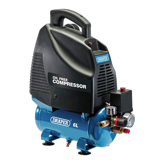
230V DIRECT DRIVE
OIL FREE
COMPRESSOR
24974
These instructions accompanying the product are the original instructions. This document is part of the product, keep
it for the life of the product passing it on to any subsequent holder of the product. Read all these instructions before
assembling, operating or maintaining this product.
This manual has been compiled by Draper Tools describing the purpose for which the product has been designed,
and contains all the necessary information to ensure its correct and safe use. By following all the general safety
instructions contained in this manual, it will ensure both product and operator safety, together with longer life of the
product itself.
All photographs and drawings in this manual are supplied by Draper Tools to help illustrate the operation of the
product.
Whilst every effort has been made to ensure the accuracy of information contained in this manual, the Draper Tools
policy of continuous improvement determines the right to make modifications without prior warning.
Advertisement
Table of Contents

Subscribe to Our Youtube Channel
Related Manuals for Draper OIL FREE COMPRESSOR


Summary of Contents for Draper OIL FREE COMPRESSOR
- Page 1 All photographs and drawings in this manual are supplied by Draper Tools to help illustrate the operation of the product.
-
Page 2: Title Page
TITLE PAGE INTRODUCTION: USER MANUAL FOR: 230V Oil Free Compressor Stock No: 24974 Part No: DA6/169 REVISIONS: Date first published September 2012. Date of first revision: May 2020. As our user manuals are continually updated, users should make sure that they use the very latest version. -
Page 3: Table Of Contents
CONTENTS TABLE OF CONTENTS TITLE PAGE INTRODUCTION: ......................2 REVISIONS: ......................... 2 UNDERSTANDING THIS MANUALS SAFETY CONTENT: ......... 2 COPYRIGHT © NOTICE: ..................... 2 CONTENTS TABLE OF CONTENTS ....................3 WARRANTY WARRANTY ......................... 4 INTRODUCTION SCOPE ......................... 5 SPECIFICATION ......................5 HANDLING AND STORAGE .................. -
Page 4: Warranty 3.1 Warranty
This warranty applies in lieu of any other warranty expressed or implied and variations of its terms are not authorised. Your Draper warranty is not effective unless you can produce upon request a dated receipt or invoice to verify your proof of purchase within the warranty period. -
Page 5: Introduction
INTRODUCTION SCOPE The compressor described in this manual is capable of supplying compressed air to a maximum pressure of 8bar. to operate pneumatic tools for a variety of applications including blowing, spraying and tyre inflating. SPECIFICATION Stock No..........................24974 Part No. -
Page 6: Health And Safety Information
HEALTH AND SAFETY INFORMATION GENERAL SAFETY INSTRUCTIONS FOR POWER TOOL USE When using any type of power tool there are steps that should be taken to make sure that you, as the user, remain safe. Common sense and a respect for the tool will help reduce the risk of injury. Read the instruction manual fully. -
Page 7: Additional Safety Instructions For Safety Valves
HEALTH AND SAFETY INFORMATION before making any adjustments, carrying out maintenance operations or just finishing using the tool. Remove and check setting tools. Some machinery requires the use of additional tools or keys to set, load or adjust the power tool. Before starting the power tool always check to make certain they have been removed and are safely away from the machine. -
Page 8: Additional Safety Instructions For Pressure Vessels
HEALTH AND SAFETY INFORMATION Maintenance and inspection: The valve must not be subject to knocks which may cause deformities. It is obligatory for qualified technicians to make sure that the safety valve functions correctly at least once a year. Valves equipped with a ring must be tested while pressurised to between 80 –... - Page 9 HEALTH AND SAFETY INFORMATION Important: If using an extension lead, follow the instructions that came with your lead regarding maximum load while cable is wound. If in doubt, ensure that the entire cable is unwound. Using a coiled extension lead will generate heat which could melt the lead and cause a fire. –...
-
Page 10: Technical Description
TECHNICAL DESCRIPTION IDENTIFICATION (10) (13) (11) (12) (1) Carry handle (10) Air filter. (2) Pressure switch ON/OFF button (11) Tank (3) Pressure regulator (12) 4 × Rubber feet (4) Air outlet quick connector (13) Motor (5) Pressure switch (6) Tank pressure gauge (7) Air outlet pressure gauge (8) Safety valve (9) Drain cock... -
Page 11: Unpacking And Checking
Lay the contents out and check them against the parts shown below. If any part is damaged or missing, please contact the Draper Help Line (the telephone number appears on the Title page) and do not attempt to use the product. -
Page 12: Preparing The Compressor
PREPARING THE COMPRESSOR Note: Remove the plug from the socket before carrying out adjustment, servicing or maintenance. (10) LOCATION AND ASSEMBLY – FIG. 1 It is extremely important to install the compressor in a clean, well ventilated area where the surrounding air temperature will not be more than 40ºC. -
Page 13: Operation
OPERATION BASIC COMPRESSOR OPERATION – FIG. 4 – Connect the air line to the compressor by pulling back the collar (4.1) on the air outlet quick coupling (4) and inserting the corresponding air coupling fitted on the air line. Release the collar so it slides back in place to secure the air coupling. -
Page 14: Thermal Overload Protector
OPERATION THERMAL OVERLOAD PROTECTOR Caution: This compressor is equipped with an automatic reset thermal overload protector, which will shut off the motor if it becomes overheated. If thermal overload protector shuts motor OFF frequently, look for the following causes. – Low voltage. –... -
Page 15: Maintenance And Troubleshooting
10. MAINTENANCE AND TROUBLESHOOTING 10.1 TROUBLESHOOTING GUIDE Problem Possible Cause Remedy Compressor will not run. 1. No electrical power. 1. Plugged in? Check fuse/ breaker or motor overload. 2. Blown fuse. 2. Replace blown fuse. 3. Breaker open. 3. Reset, determine cause of problem. - Page 16 10. MAINTENANCE AND TROUBLESHOOTING Thermal overload protector 1. Low voltage. 1. Eliminate extension cord, cuts out repeatedly. check with voltmeter. 2. Clogged air filter. 2. Clean filter (see maintenance section). 3. Lack of proper ventilation/ 3. Move compressor to well room temperature too ventilated area.
-
Page 17: Basic Maintenance And Checks - Fig. 6
10. MAINTENANCE AND TROUBLESHOOTING Excessive moisture in 1. Excessive water in tank. 1. Drain tank. discharge air. Compressor runs 1. Defective pressure switch. 1. Replace switch. continuously and safety 2. Defective safety valve. 2. Replace safety valve with valve opens as pressure genuine replacement part. -
Page 18: Draining Water From The Tank - Fig. 7
10. MAINTENANCE AND TROUBLESHOOTING 10.3 DRAINING WATER FROM THE TANK – FIG. 7 The drain cock (9) is located on the bottom of the tank. Use this valve to drain moisture from the tank daily to reduce the risk of corrosion. –... -
Page 19: Explanation Of Symbols
11. EXPLANATION OF SYMBOLS 11.1 EXPLANATION OF SYMBOLS Read the Remove from instruction Tank air capacity packaging. manual. Wear face mask Motor capacity and safety ON/OFF switch. (Kilowatts). glasses. Wear ear Lift button to Motor capacity defenders. switch on. (Horse power). Max. -
Page 20: Disposal
12. DISPOSAL 12.1 DISPOSAL – At the end of the machine’s working life, or when it can no longer be repaired, ensure that it is disposed of according to national regulations. – Contact your local authority for details of collection schemes in your area. In all circumstances: •... - Page 21 NOTES – 21 –...
- Page 22 NOTES – 22 –...
- Page 23 NOTES – 23 –...
- Page 24 ©Published by Draper Tools Limited. No part of this publication may be reproduced, stored in a retrieval system or transmitted in any form or by any means, electronic, mechanical photocopying, recording or otherwise without prior permission in writing from Draper Tools Ltd.
Need help?
Do you have a question about the OIL FREE COMPRESSOR and is the answer not in the manual?
Questions and answers