Sign In
Upload
Manuals
Brands
Nivus Manuals
Transmitter
NivuFlow Mobile 550
Nivus NivuFlow Mobile 550 Manuals
Manuals and User Guides for Nivus NivuFlow Mobile 550. We have
2
Nivus NivuFlow Mobile 550 manuals available for free PDF download: Instruction Manual
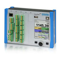
Nivus NivuFlow Mobile 550 Instruction Manual (163 pages)
Flow measurement transmitter
Brand:
Nivus
| Category:
Transmitter
| Size: 8.38 MB
Table of Contents
Copyrights and Property Rights
3
Document Modifications
4
Table of Contents
5
General
10
Signs and Definitions Used
10
Abbreviations Used
11
Colour Code for Wires and Single Conductors
11
1 About this Manual
10
Applicable Documentation
10
2 Connections and Operating Elements
11
Power Supply
11
Transmitter
11
Nivuflow Mobile Operating Elements
12
Rechargeable Batteries
12
Interfaces
13
Safety Instructions
14
3 Used Symbols and Signal Words
14
Valuation of the Accident Level
14
4 Safeguards and Precautions
15
Warning Notices on the Product (Option)
15
5 Warranty
17
6 Liability Disclaimer
17
7 Use in Accordance with the Requirements
17
8 Ex Protection
18
9 User's Responsibilities
19
10 Personnel Requirements
20
Delivery, Storage and Transport
21
11 Delivery
21
12 Reception Inspection
21
13 Storage
22
14 Transport
22
15 Return
22
Product Specification
23
16 Product Construction and Overview
23
17 Device Identification
24
Directly Connectable Sensors
24
Enclosure Dimensions
24
18 Specifications
26
19 Configuration/Device Types
27
Functional Description
29
20 Operating Ranges
29
Flow Velocity Determination - Doppler Principle
29
21 Functional Principles
29
Level Measurement
30
Installation and Connection
31
22 In General
31
Installation Place
31
Before Installation
32
Connection Sockets
32
Gaskets
32
PU Stickers on Enclosure Frame
32
Securing the Instrument
32
23 Electrical Installation/Power Supply
33
Rechargeable Battery Pack
33
Removing/Inserting the Rechargeable Battery Pack
34
Charging the Rechargeable Battery Pack
35
Operation/Charging Via an Alternative Power Supply
37
Operation/Charging with Direct Connection to Mains Power
38
24 Sensor Installation
38
Sensor Installation Basics
38
Cable for Sensor Connection
39
25 Connection of Sensors
39
Definition of Channel Shape
39
Installation of the Level Sensor
39
Installation of the Radar Sensor
39
Overvoltage Protection Measures
40
Sensor Connection
40
26 Single External Connection for Inputs/Outputs
41
27 Connecting the Connector Box for Inputs/Outputs
41
28 (T-Shape) Antenna for GPRS Data Remote Transmission
43
Putting into Operation
44
29 Notes to Users
44
30 Indication System of Status LED on Nivuflow Mobile
44
Android Operating System
45
General
45
31 Setting up Connection
45
Ios Operating System
48
Windows Operating System
51
Display Overview
54
32 Menu Operation/Overview
54
Saving Parameters
55
Menus
56
Commissioning Example
57
33 Contactless Measurement in a Rectangular Channel
57
Easy Parameterisation Process in a Specific Example
57
General
57
Main Display
60
34 Functions of the Main Display
60
Parameter Setting
66
35 General Programming
66
Change WLAN Password
66
Save Parameters
66
Change Instrument SSID
67
Lost Password
67
Automatic Data Transmission to USB Stick
68
36 Parameter Setting Using Quick Start
68
Functions of the First Menu Level
72
Main Menu
72
Menu - Application
72
37 Parameter Functions
72
Menu - Data
73
Menu - System
74
Menu - Communication
75
Menu - Display
75
Menu - Battery (12V)
76
Menu - Quick Start
76
Menu - Alert
77
38 Parameters Menu Application
77
Channel Profiles
78
Menu Measure Place
78
Name of Measurement Place
78
Low-Flow Suppression
83
View
83
Damping
84
Stability
84
Menu H-Sensors
85
Menu V-Sensor 1
85
Sensor Types
85
Mounting Data
86
V-Determination Low Levels
86
V-Minimum and V-Maximum
86
Menu Inputs/Outputs (Analog and Digital)
88
Analog Inputs
89
Analog Outputs
90
Digital Inputs
91
Digital Outputs
92
Menu Diagnostics
93
Menu Trend
94
39 Parameters Menu Data
94
Menu Day Totals
95
Menu Data Memory
97
Menu Information
99
40 Parameters Menu System
99
Date Format
100
Menu Region Settings
100
Operation) Language
100
Units
100
Data Units
102
Menu Time/Date
103
Menu Error Messages
104
Menu Service
104
Feature Unlock
105
Parameter Reset
105
Powerdown
105
Restart
105
Service Level
105
Update Bootloader
108
Update Nivuflow
108
Menu Storage Mode
109
41 Parameters Menu Communication
110
42 Parameter Menu Display
115
43 Parameter Menu Battery (12V)
116
Menu >Quick Start< / >Region Settings
117
44 Parameter Menu Quick Start
117
Menu >Quick Start< / >H-Sensors
118
Menu >Quick Start< / >Measure Place
118
Menu >Quick Start< / >Analog Input X
119
Menu >Quick Start< / >V-Sensor 1
119
Menu >Quick Start< / >Digital Input 1
120
45 Parameter Menu Alert
120
Menu >Alert< / >Flow
121
Menu >Alert< / >Level
121
Menu >Alert< / >Velocity
122
Menu >Alert< / >Air Temperature
123
Menu >Alert< / >Battery (12V)
123
Menu >Alert< / >Analog Input 1
124
Menu >Alert< / >Analog Input 2
125
Menu >Alert< / >Analog Input 3
126
Menu >Alert< / >Digital Input
127
Diagnostics
128
46 Diagnostics Menu Principles
128
47 Menu Diagnostics H-Sensors
129
48 Menu Diagnostics V-Sensor
129
Important Information on the Simulation
130
49 Menu Diagnostics Inputs/Outputs
130
50 Menu Diagnostics Signal Analysis
132
51 Menu Diagnostics Simulation
133
Maintenance and Cleaning
134
52 Maintenance
134
Maintenance Interval
134
53 Cleaning
135
Customer Service Information
135
Power Adapter / Battery Charger
135
Sensors
135
Transmitter
135
54 Dismantling/Disposal
136
55 Installation of Spare Parts and Parts Subject to Wear and Tear
136
56 Accessories
136
Index
138
Credits and Licenses
141
57 List of References of the Licenses and Codes Used
141
Approvals and Certificates
142
Advertisement
Nivus NivuFlow Mobile 550 Instruction Manual (124 pages)
Flow Measurement Transmitter for Radar Sensors
Brand:
Nivus
| Category:
Transmitter
| Size: 5.72 MB
Table of Contents
Copyrights and Property Rights
2
Modifications
3
Table of Contents
4
General
10
Signs and Definitions Used
10
Abbreviations Used
11
1 About this Manual
10
Applicable Documentation
10
2 Connections and User Elements
11
Power Supply
11
Nivuflow Control Elements
12
Tasks of Control Elements
12
Interfaces
13
Safety Instructions
14
3 In General: Used Symbols and Signal Words
14
Valuation of the Accident Level
14
4 Safeguards and Precautions
15
Warning Notices on the Product
15
5 Liability Disclaimer
16
6 Use in Accordance with the Requirements
16
7 User's Responsibilities
17
8 Personnel Requirements
18
Product Specification
19
9 Product Construction and Overview
19
Dimensions of Enclosure
19
Connectable Sensors
20
Device Identification
20
10 Specifications
22
11 Configuration
23
Device Types
23
Delivery
23
Reception Inspection
23
Storing
24
Transport
24
Return
24
Installation of Spare Parts and Parts Subject to Wear and Tear
24
Functional Principle
25
12 Operating Range
25
13 Functional Principles
25
Flow Velocity Measurement
25
Surface Radar
25
Level Measurement
26
External Level Sensor
26
Installation and Connection
27
14 Installation Instructions
27
Choosing the Installation Place
27
Hints on How to Avoid Electrostatic Discharge (ESD)
27
15 Electric Installation
28
Power and Relay Connections
29
Clamps for Protective Conductor Terminal and AC Supply
29
Power Supply DC
29
Power Supply AC
29
Relays
30
Fastening the Transmitter
28
16 Installation of Sensors
31
Sensor Installation Principles
31
Preparations for Sensor Installation
31
17 Sensor Connection
32
Cable and Cable Lengths for Sensor Connection
32
Sensor Connection at Nivuflow
33
Overvoltage Protection
35
18 Transmitter Connection
38
Connection to the Terminal Blocks
38
Connection Diagrams
39
Switching on Voltage Supply
40
Operation Start-Up
42
19 Notes to Users
42
20 Operation Basics
43
Display Overview
43
Using the Control Elements
43
Use/Entry Using the Letter Block
44
Use/Entry Using the Numeric Keypad
45
Revision of Parameters
46
Menus
46
Setting Parameters
47
21 General Programming
47
Change Password
47
Save Parameters
47
22 Parameter Functions
48
Main Menu
48
Functions Top Menu Level
48
Application Menu
48
Data Menu
49
System Menu
50
Communication Menu
50
Display Menu
51
Connections Menu
51
23 Description of Parameters
52
Setting the Measurement Place Parameters (Application Menu)
52
Name of Measurement Place
52
Channel Profiles
53
Sludge Level
58
Flow Velocity Evaluation
58
Low-Flow Suppression
59
Damping
60
Stability
60
Setting Parameters in H-Sensors Menu
60
H-Sensor Types
60
Definition Of Measurement Ranges
62
Setting Parameters in V-Sensors Menu
65
Number of Flow Velocity Sensors
65
Sensor Types
65
Sensor Mounting Position
65
V-Minimum and V-Maximum
67
Data Transmission Rate
67
Inputs and Outputs (Analog and Digital)
68
Analog Inputs
68
Analog Outputs
70
Digital Inputs
72
Digital Outputs
74
Diagnosis
77
24 Data Parameter Menu
78
Trend
78
Day Totals
81
USB-Transfer
82
Data Memory (Internal)
87
25 System
88
Information
88
Language Settings
89
Operation) Language
89
Date Format
89
Units
89
Memory Units
91
Time/Date
92
Error Messages
93
Service
93
Change (System) Password
94
Restart
94
Measurement Restart
94
Parameter Reset
95
26 Communication Parameters Menu
95
27 Display Parameters Menu
97
28 Connections
99
Main Display
100
29 General Overview
100
Display Flow
101
Menu Settings (Flow)
102
Menu Diagnostics (Flow)
102
Menu Display (Flow)
103
Menu Error Messages (Flow)
103
Display Level
104
Menu Settings (Level)
104
Menu Diagnostics (Level)
105
Menu Display (Level)
105
Display Velocity
105
Menu Settings (Velocity)
106
Menu Diagnostics (Velocity)
106
Display Temperature and Sum
107
Display Trend/Hydrograph
107
Diagnosis
108
30 Basics of Diagnosis Menus
108
31 Diagnosis H-Sensors
109
32 Diagnosis V-Sensors
110
33 Inputs and Outputs (Analog and Digital)
111
Analog Inputs
111
Analog Outputs
112
Digital Inputs
114
Digital Outputs
114
34 Simulation
116
Maintenance and Cleaning
118
35 Maintenance
118
Maintenance Interval
118
Customer Service Information
118
36 Cleaning
119
Transmitter
119
Sensors
119
37 Dismantling/Disposal
119
38 Accessories
120
Advertisement
Related Products
Nivus NivuFlow Mobile 550 Ex
Nivus NivuFlow Mobile 600
Nivus NivuFlow Mobile 600 Ex
Nivus NivuFlow Mobile 750 Ex
Nivus NivuFlow 650
Nivus NivuFlow 750
Nivus OCM F
Nivus Categories
Measuring Instruments
Transmitter
Surge Protector
Accessories
Data Loggers
More Nivus Manuals
Login
Sign In
OR
Sign in with Facebook
Sign in with Google
Upload manual
Upload from disk
Upload from URL