Advertisement
Quick Links
GTE Industrieelektronik GmbH
KMG-2000-G
compliant - according to the BIA (Professional Institute for Health and Safety at Work) - with
DIN EN 12453 - "Gates - Safe Use of Power-Operated Gates - Test Procedures"
and DIN 16005 – "Automatic Door Systems"
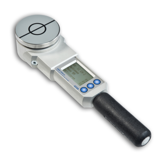
Handheld measuring device for determining the
dynamic and static forces at the closing edges of
doors and gates.
GTE Industrieelektronik GmbH
Helmholtz Str. 38 - 40
D-41747 VIERSEN
Tel.: ++49 - (0)2162 3703 - 0
Fax.:++49 - (0)2162 3703 - 25
www.gte.de
Advertisement

Related Manuals for GTE KMG-2000-G


Summary of Contents for GTE KMG-2000-G
- Page 1 GTE Industrieelektronik GmbH KMG-2000-G compliant - according to the BIA (Professional Institute for Health and Safety at Work) - with DIN EN 12453 - “Gates - Safe Use of Power-Operated Gates - Test Procedures” and DIN 16005 – “Automatic Door Systems”...
- Page 2 GTE Industrieelektronik GmbH 1. Technical Data Power supply: 2 x 1.2V NiMH accumulators Power consumption: 20 mA Interface: Number of graphs stored: 500 single measurements equal to 166 normal measurements each with 3 individu- al measurements Temperature range: -10 ..+60°C Relative humidity: 20 - 90 % r.h.
- Page 3 2. Introduction The KMG-2000-G force-measuring device is used for the determination of dynamic and static forces as well as the duration of these at the closing edges of doors and gates. According to the standard, three single measurements must be made at each test point for a normal measurement, the mean value of which then represents the measured value that is relevant for standard purposes.
- Page 4 The measuring device consists essentially of a measuring body complete with the test sur- face, a centrepiece complete with electronics and a display, and the handgrip complete with a battery compartment (Picture 1). Picture 1: KMG-2000-G Force-Measuring Device V3.2UK 2/19 KMG-2000-G...
- Page 5 He will then test that it is compliant and approve the device for use for an- other year. 3.3. The centrepiece of the KMG-2000-G contains an LCD display, on which all the measured values, the force curves, the measured-value memory management func- tion and user guidance are displayed.
- Page 6 GTE Industrieelektronik GmbH 4. Measurement of a Force Sequence 4.1 Carrying Out The Force Measurement • Switch on (actuate any button as desired) After switching on, the “start” display appears for KMG-2000-G GTE 5 seconds: Options Language During this time the language selection or the Exit options menu can be selected.
- Page 7 GTE Industrieelektronik GmbH Once measuring has been completed, the Measurement is calculated force/time graph is analysed automatically and the values that are relevant to the standard are Please wait determined. • Display measured values Following evaluation, the course of the force over...
- Page 8 USB jack on the KMG-2000 G and to a USB inter- face on the PC. Before data can be read off the KMG-2000-G the device must be switched on and the ‘KMG-VD 2005’ program on the computer which has been connected up must be started.
-
Page 9: Option 1: Activation Mode
GTE Industrieelektronik GmbH 5. Menu Options 5.1 General Advice The function keys F1, F2 and F3 are used for calling up menu functions and for operating the device. The function of the keys is given by the symbols F1, F2 and F3 on the display. - Page 10 GTE Industrieelektronik GmbH 5.2.2 Delete Mode = F2 Options (2/6) In order to prevent accidental deletion, button F2 must Next function be pressed for longer than 3 seconds. Delete results Exit The following delete functions can be selected on the...
-
Page 11: Lighting Adjustment
GTE Industrieelektronik GmbH 5.2.4 Lighting Adjustment Options (4/6) Next function On this menu the lighting of the display can be Illumination Exit switched on or off using button F1. 5.2.5 Annunciator On this menu the internal annunciator can be switched... -
Page 12: Language Selection
GTE Industrieelektronik GmbH 5.3 Language Selection KMG 2007 GTE Options Language selection is only available after the Language device is switched on. As the device does not Cancel have an off-switch, you must wait until it switches off automatically and then switch the device back... - Page 13 GTE Industrieelektronik GmbH 6. Warning and Error Messages 6.1 Battery Monitoring Whilst in operation the state of the rechargeable Charge battery is checked. If the battery is really low, the batteries following message appears: Exit With the present level of charge further measure- ments can still be made.
- Page 14 By pressing the key F3 the measurement can still be started ignoring the current load. However in this case the measurement accuracy will not be granted! If this warning is indicated without a load on the measurement area, the force gauge should be sent for maintenance to the GTE service department. V3.2UK 2/19 KMG-2000-G...
-
Page 15: Sliding Door
GTE Industrieelektronik GmbH Extract from DIN EN 12453 Safety in use of power operated doors – Test methods – Measuring Points A measuring point is the place where the measurement of entrapment forces at doors must be made. Three (3) measurements must be taken at each measuring point. - Page 16 GTE Industrieelektronik GmbH Figure 1: Measuring points at the leaf of a sliding door. Figure 2: Opening widths between the primary closing edge of a sliding door and the counter edge V3.2UK 2/19 KMG-2000-G Page 16 of 26...
- Page 17 GTE Industrieelektronik GmbH 3.2.1.1.1 Measuring Points Measurement of forces shall be carried out at the height of 50 mm above the lower edge of the door, the middle of the primary closing edge, or, at a height of 2500 mm...
- Page 18 GTE Industrieelektronik GmbH 3.2.2 Hinged doors On hinged doors, the entrapment forces must be measured on both the pri- mary closing edge and the door leaf itself as shown below, in figures 3 and 4: Figure 3: Measuring points at the leaf of a hinged door V3.2UK 2/19...
- Page 19 GTE Industrieelektronik GmbH Figure 4: Opening widths between the leaf of a hinged door and the counter closing edge 3.2.2.1 Measuring between the primary and the counter closing edges 3.2.2.1.1 Measuring points: Measurement should be carried out at the height of...
- Page 20 GTE Industrieelektronik GmbH 3.2.2.1.2 Direction of Measuring Force The forces are to be measured in the direction orthogonal to the closing edge defined, in the plan, by the closing door edge and the counter closing edge. NOTE : The counter closing edge facing the leaf has been radiused of more than 3 mm.
- Page 21 GTE Industrieelektronik GmbH 3.2.2.2.1 Measuring Points Measurement must be carried out at a distance of 1000 mm from the pivots of the door leaf, or, at the primary closing edge where the width of the leaf is less than 1000 mm,...
- Page 22 GTE Industrieelektronik GmbH 3.2.3.2 Measuring between the door leaf and surrounding solid parts Measurement of entrapment forces should be carried out between a folding leaf and the surrounding solid parts with regard to the direction of the meas- uring force at the measuring points as required for hinged doors (3.2.2.).
- Page 23 GTE Industrieelektronik GmbH Figure 6: Measuring points at the leaf of a lifting door and in the door space. Figure 7: Door space between the primary and counter closing edges of a lifting door V3.2UK 2/19 KMG-2000-G Page 23 of 26...
- Page 24 GTE Industrieelektronik GmbH 3.2.4.2 Direction of Measuring Force The force is measured in a direction orthogonal to ground level. 3.2.5 Tilting doors On tilting doors, the entrapment forces should be measured on the primary and secondary closing edges as follows: 3.2.5.1...
- Page 25 GTE Industrieelektronik GmbH 3.2.5.2 Measuring forces between secondary closing edge and counter edge Entrapment forces have to be measured between closing edge and counter edge (walls, lintel) as stated below: The entrapment force is measured against the movement, perpendicular to the door leaf, 300 mm from the point where it passes the static edge and when the angle between the door leaf and the fixed edge is 30°...
- Page 26 GTE Industrieelektronik GmbH 3.2.6.2 Measuring Direction The impact force is to be measured perpendicular to the arm’s ownwards movement (see figure 9 a, b, c). Figure 9: Measuring points of measuring at a barrier V3.2UK 2/19 KMG-2000-G Page 26 of 26...
Need help?
Do you have a question about the KMG-2000-G and is the answer not in the manual?
Questions and answers