Table of Contents
Advertisement
Quick Links
Advertisement
Table of Contents

Related Manuals for tousek ST 80


Summary of Contents for tousek ST 80
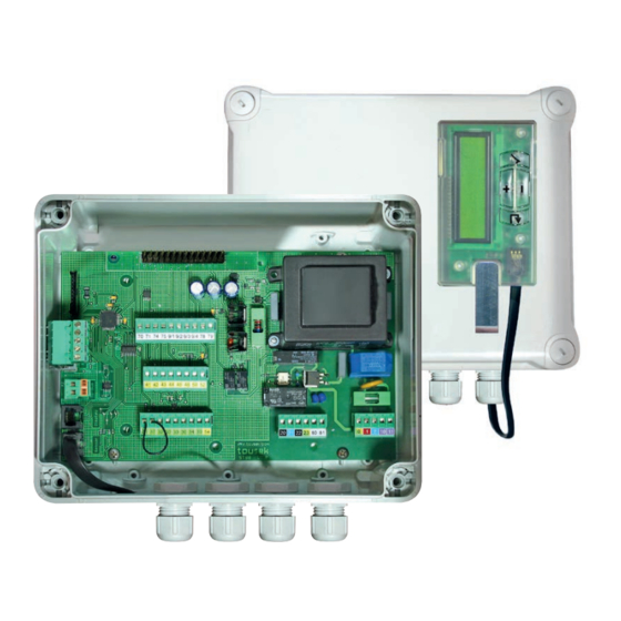
- Page 1 Installation and connection manual Barrier control unit ST 80, ST 80V...
-
Page 2: Table Of Contents
Dimensioned drawing ..........................22 This manual is the sole property of the TOUSEK Ges.m.b.H. and may not be made available to competitors. All rights reserved. No part of it may be reproduced without our prior written permission. We will not accept liability for any claims resulting from misprints or errors. This edition of the manual replaces all earlier publications of the same. -
Page 3: General Warning And Safety Details
EU and in the individual countries have to be strictly followed. • The TOUSEK Ges.m.b.H. cannot be held liable for any claims resulting from disregards of the laws and standards in force during the installation and operation. -
Page 4: Notes, General Characteristics, Control Board Layout
General Barrier control unit ST 80, ST 80V Control board characteristics • For barriers with electromech. motors 230V and speed • Automonitoring of photocell sensor • Ouput for Photocells, magnetic clamp, signal lamp and boom • Programming with illuminated LC display in englisch language lamp kit •... -
Page 5: Technical Data, Terminal Assignment, Connection Notes
• additional module for status of barrier • induction loop detector • other Optional equipment impulse givers and safety equipment Terminal assignment Barrier control unit ST 80, ST 80V Warning • Before taking off the control cover, the mains switch must be turned off! •... -
Page 6: Adjustments - Overview
Adjustments - overview Barrier control unit ST 80, ST 80V Programming buttons Adjustment - overview • Before starting the programming, please choose the language. Use the buttons to choose menu langu- age and confirm with • Note: Language selection can also be chosen by pressing the ESC button ( ) for 5s, from any position in menu. -
Page 7: Menus
display protocol messages sensor status display sensor At barriers with 6m boom length the settings for speed OPEN/CLOSE must not be more than 90% (= factory setting of ST 80)! ENTER Barrier control unit ST 80, ST80V - 7 -... -
Page 8: Connections And Adjustments
Connections and adjustments Barrier control unit ST 80, ST 80V Warning • Before taking off the control cover, the • The product is not suitable for installation in explosion- mains switch must be turned off! hazardous areas. • If the control is power supplied, its inner part is under •... -
Page 9: Isd Channel 1 (I-Loop 1: Terminals 9/1 And 9/2)
The stop input has no emergency stop function! - In order to ensure the emergency stop function, provide the supply line with an all-pole disconnecting emergency stop switch, that locks after actuation! - 9 - tousek / EN_ST-80_80601606 / 25. 03. 2020... -
Page 10: Partial Opening Switch (Terminals 30/34)
Photocell Tousek LS 26 transmitter receiver as safety device Important 12/24V 12/24V NC C NO • Jumper J of transmitter and receiver has to be adjusted in the same way. - 10 - tousek / EN_ST-80_80601606 / 25. 03. 2020... - Page 11 2 photocells Tousek LS 41 / LS 180 2 photocells Tousek LS 41 / LS 180 as safety as safety device device with SYNC-function activated transmitter 1 receiver 1 transmitter 1 receiver 1 SYNC SYNC receiver 2 transmitter 2 transmitter 2...
-
Page 12: G Main Closing Edge (Terminals 50/52)
• The photocell self-test can only be deactivated by selecting „not active“. • The deactivation of the self-test function is only permitted if the safety installations correspond to the category 3 ! - 12 - tousek / EN_ST-80_80601606 / 25. 03. 2020... -
Page 13: Motor
Forced closing (only with ST 80V) Operating logic active: this function causes that a manually released boom goes immediately back to closure. not active: the forced closing is deactivated - 13 - tousek / EN_ST-80_80601606 / 25. 03. 2020... -
Page 14: Lamps / Lights
• Note: The kit for round booms (Product No. 13710250) must be connected via a specially dimensioned series resistor (R boom lamp) to the control board ST 80 (see figure), the kit for flat booms (Art.Nr. 13710190) without a resistor. -
Page 15: Peripherals
(R magnet) to the controller ST 80. Connection of magnet • ATTENTION: turn off power supply! • The magnet has to be connected to the control ST 80 via a protective resistor. This protective resistor is designed for the tousek adhesive magnets GD 70. -
Page 16: Diagnosis
HOURS : MINUTES : SECONDS $$$$$$$$$$$$$$$$ T -00 00:00:00.0 event type $$$$$$$$$$$$$$$$ Event Status Sensor (control function) Reset / Diagnosis Degree and signal strength of rotation speed sensor is shown on display. - 16 - tousek / EN_ST-80_80601606 / 25. 03. 2020... -
Page 17: Induction Loop Detector (Optional)
• Reset: average duration of the key press (> 2s), reset the detector, subsequent initialization of all channels. Insert the board of the induction loop de- tector on the slot (ISD) of the control board. ST 80(V) - 17 - tousek / EN_ST-80_80601606 / 25. 03. 2020... -
Page 18: Radio Receiver (Optional)
Connecting the receiver Barrier control unit ST 80, ST 80V (optional) Important • Turn off power supply. • With the use of the 2-channel-receiver the second • Open cover of control unit channel takes over the function of the partial opening •... -
Page 19: Modul Status Display (Optional)
Status display module Barrier control unit ST 80, ST 80V (optional) Important • The optional module „Status display“ has to be plugged onto the connector slot (ZM) of control board and enables the evaluation of boom position or boom movement. -
Page 20: Inbetriebnahme
Putting into operation Barrier control unit ST 80, ST 80V Important: preparation works • Connect control panels, safety devices to the motor under consideration of the safety regulations . Attention: if no stop switch is connected then the terminals 31/37 have to be bridged. - Page 21 After giving the impulse to automatically program the end positions, no other impulse must be given. Also the safety devices mustn´t be triggered. This would lead to an interruption of the programming process. - 21 - tousek / EN_ST-80_80601606 / 25. 03. 2020...
-
Page 22: Erroy Analysis
Error search Barrier control unit ST 80, ST 80V Error possible reason solution stop-button not connected or not Stop-button (Kl. ) connect or bridge > Display: „Stop-button triggered“ bridged use status display for help check correct connection hence Display: „Photocell triggered“... - Page 24 Buitenheide 2A/ 1 Tel. +32/ 11/ 91 61 60 your service partner: Fax +32/ 11/ 96 87 05 info@tousek.be Tousek Sp. z o.o. Poland PL 43-190 Mikołów (k/Katowic) Gliwicka 67 Tel. +48/ 32/ 738 53 65 Fax +48/ 32/ 738 53 66 info@tousek.pl...
Need help?
Do you have a question about the ST 80 and is the answer not in the manual?
Questions and answers