Table of Contents
Advertisement
Quick Links
Advertisement
Table of Contents

Subscribe to Our Youtube Channel
Related Manuals for tousek ST 51


Summary of Contents for tousek ST 51
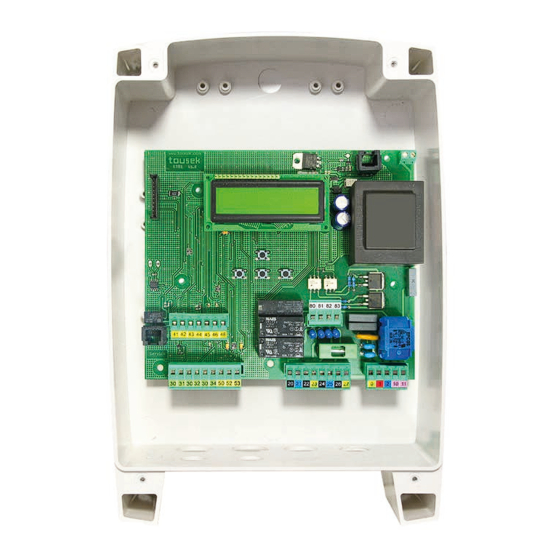
- Page 1 Connection and installation manual Swing gate control unit ST 51...
-
Page 2: Table Of Contents
Dimensioned drawing housing IP54 ....................... 27 This manual is the sole property of the TOUSEK Ges.m.b.H. and may not be made available to competitors. All rights reserved. No part of it may be reproduced without our prior written permission. We will not accept liability for any claims resulting from misprints or errors. This edition of the manual replaces all earlier publications of the same. -
Page 3: General Warning And Safety Notes
EU and in the individual countries have to be strictly followed. • The TOUSEK Ges.m.b.H. can not be held liable for any claims resulting from disregards of the laws and standards in force during the installation and operation. - Page 4 General features Swing gate control unit ST 51 Control board features • suitable for swing gates with electromechanical operators • Separate force adjustment for opening and closing movement 230V (1 or 2 gate leafs) • Operating mode: impulse-, automatic- or deadman mode •...
- Page 5 Terminal assignment Swing gate control unit ST 51 Warning • The product is not suitable for installation in explosion- • Before taking off the control cover, hazardous/explosive areas. the mains switch must be turned off ! • An all-pole disconnecting mains switch with a contact •...
-
Page 6: Adjustments - Overview
Adjustments - overview Swing gate control unit ST 51 Programming buttons Adjustments - Overview • The adjustment (programming) of the operating parameters is carried out via four programming buttons and the text display. • Before you can start programming, select the language of the display. You can do this by pressing the + or - and choose the language for the menuas and press ENTER. -
Page 7: Menu Structure
factory setting see page 20 Software version shows software version serial number shows serial number protocol shows protocol events ENTER Swing gate control unit ST51 - 7 - tousek / E_ST51_04 / 11. 05. 2015... -
Page 8: Connections And Adjustments
Connections and adjustments Swing gate control unit ST 51 Warning • The product is not suitable for installation in explosion- • Before taking off the control cover, the hazardous areas. main switch must be turned off! • An all-pole disconnecting main switch with a contact •... -
Page 9: Pedestrian Button (Terminals 30/34)
(e.g. switch KDT-1N)) minals 30/31 have to be wire-bridged. A break contact has to be used as stop switch. If the switch is actuated, the gate stops in any desired position. - 9 - tousek / E_ST51_04 / 11. 05. 2015... -
Page 10: Safety
Outer Photocell (contact: terminals 45/48) Safety active: to be selected, if outer photocell should be triggered. not active: to be selected, if outer photocell should not be triggered. - 10 - tousek / E_ST51_04 / 11. 05. 2015... -
Page 11: Photocells - Connection Examples
Tousek RLS 610 as safety device transmitter receiver 12/24V 12/24V NC C NO 24Va.c. Important • Jumper J of transmitter and receiver has to be adjusted in the same way. - 11 - tousek / E_ST51_04 / 11. 05. 2015... -
Page 12: Safety Contact Edges
• IMPORTANT: during programming of motor the contact safety edges should not be triggered as this leads to an error message - the limit stops have to be placed correspondingly. - 12 - tousek / E_ST51_04 / 11. 05. 2015... - Page 13 - 13 - tousek / E_ST51_04 / 11. 05. 2015...
-
Page 14: Photocell Function Inside
• The photocell self-test can only be deactivated by selecting „not active“. • The deactivation of the self-test function is only permitted if the safety installations correspond to the category 3 ! - 14 - tousek / E_ST51_04 / 11. 05. 2015... -
Page 15: Motor Connection
• The placement of the condensers can be chosen freely, but we recommend the lower area of the operator control housing, as shown on picture. - 15 - tousek / E_ST51_04 / 11. 05. 2015... -
Page 16: Left Leaf
5s (factory setting) Soft stop time Linker Flügel page15): max. force OPEN = 100% 0–25s adjustable: indicates the set softstop time. max. force CLOSE = 100% soft-stop time = 0 - 16 - tousek / E_ST51_04 / 11. 05. 2015... -
Page 17: Operating Mode
OFF 0,1–3,0s adjustable: at the end of the closing movement the motor force is increased for this time in order to grant a proper locking of the gate. - 17 - tousek / E_ST51_04 / 11. 05. 2015... -
Page 18: Light / Lamps
• Follow safety instructions (see page 8) ! connection works, the power supply of the facility has to be turned off. • A flashing light with 230V, max. 40W can be connected at the terminals 10/11. - 18 - tousek / E_ST51_04 / 11. 05. 2015... -
Page 19: Peripherals
Peripherals Connections and adjustments Optional module for electric lock/magnetic clamp • The control unit ST 51 needs an optional module for connection of an electric lock/magnet (12V or 24Vd.c. version depending on electric lock). Connection of module • ATTENTION: turn off power supply! •... -
Page 20: Diagnosis
+ and - the single events can be seen: With the protocole beginning Time since the last event: DAYS HOURS : MINUTES : SECONDS hence the end is shown $$$$$$$$$$$$$$$$ T -00 00:00:00.0 $$$$$$$$$$$$$$$$ Event Type of event - 20 - tousek / E_ST51_04 / 11. 05. 2015... - Page 21 Connecting the receiver Swing gate control unit ST 51 • Disconnect the power supply Important • Plug-in the receiver printed circuit board (E) RS433/868- • With the use of the 2-channel-receiver the second STN1 (1 channel) or RS433/868-STN2 (2 channels)) channel takes over the function of the pedestrian into the corresponding slot (FE) as shown in the picture.
-
Page 22: Initial Operation
Putting into operation Swing gate control unit ST 51 Important: preparation works • Connect control panels, safety devices to the motor under the safety regulations in . Attention: if no stop switch is connected then the terminals 30/31 have to be bridged. - Page 23 $$$$$$$$$$$$$$$$ mainsafety edge1 $$$$$$$$$$$$$$$$ mainsafety edge1 $$$$$$$$$$$$$$$$ $$$$$$$$$$$$$$$$ active confirm left (term. 50/52) $$$$$$$$$$$$$$$$ mainsafety edge1 $$$$$$$$$$$$$$$$ not active confirm left (term. 50/52) $$$$$$$$$$$$$$$$ mainsafety edge1 $$$$$$$$$$$$$$$$ radio edge TX - 23 - tousek / E_ST51_04 / 11. 05. 2015...
- Page 24 $$$$$$$$$$$$$$$$ delay time left $$$$$$$$$$$$$$$$ e.g.10s change ? YES $$$$$$$$$$$$$$$$ delay right leaf $$$$$$$$$$$$$$$$ delay right leaf $$$$$$$$$$$$$$$$ $$$$$$$$$$$$$$$$ closing delay confirm $$$$$$$$$$$$$$$$ delay right leaf $$$$$$$$$$$$$$$$ opening delay - 24 - tousek / E_ST51_04 / 11. 05. 2015...
- Page 25 • IMPORTANT: With 1 leaf gate installation, only the operator of the actually existing gate leaf must be activated in the main menu, the other one has to be disabled (deactivated) ! (In Main Menu: Left(Right) leaf / Motor / „Motor OFF“) - 25 - tousek / E_ST51_04 / 11. 05. 2015...
- Page 26 Troubleshooting guide Swing gate control unit ST 51 Error possible reason solution mains voltage missing control of mains voltage as well as of or fuse F1 defective fuse F1 No reaction after emitting a command Display: error stop button check if stop button is properly con-...
-
Page 27: Dimensioned Drawing Housing Ip54
Dimensioned drawing housing IP54 Swing gate control unit ST 51 • dimensions in mm We reserve the right to change dimensions and technical specifications without prior notice. - 27 - tousek / E_ST51_04 / 11. 05. 2015... - Page 28 Tel. +49/ 8654/ 77 66-0 Fax +49/ 8654/ 57 196 info@tousek.de Tousek GmbH Switzerland CH-6275 Ballwil Bahnhofstraße 14 Tel. +41/ 0/ 41 448 2965 Fax +41/ 0/ 41 448 2966 info@tousek.ch Tousek Benelux NV BE-3930 Hamont - Achel Buitenheide 2A/ 1 Tel. +32/ 11/ 91 61 60 Fax +32/ 11/ 96 87 05 info@tousek.nl your service partner: Tousek Sp. z o.o. Poland PL 43-190 Mikołów (k/Katowic) Gliwicka 67 Tel. +48/ 32/ 738 53 65 Fax +48/ 32/ 738 53 66 info@tousek.pl Tousek s.r.o. Czech Republic CZ-130 00 Praha 3 Jagellonská 9 Tel. +420/ 2/ 2209 0980 Fax +420/ 2/ 2209 0989 info@tousek.cz tousek We reserve the right to change dimensions and/or technical specifications with- E_ST51_04 out prior notice. Claims resulting from misprints or errors cannot be accepted.
Need help?
Do you have a question about the ST 51 and is the answer not in the manual?
Questions and answers