Carrier RTU Open Controls, Start-Up, Operation And Troubleshooting
Multi-protocol controller, factory-installed option
Hide thumbs
Also See for RTU Open:
Table of Contents
Advertisement
Controls, Start-Up, Operation and
48/50FC04-07, 50FCQ, 48/50GC04-06, 50GCQ, 48/50KC04-06, 50KCQ04-06,
48/50HC-4-28, 50HCQ04-12, 48/50LC04-26, 48/50TC07-30, 50TCQ07-24
SAFETY CONSIDERATIONS . . . . . . . . . . . . . . . . . . . 2
GENERAL . . . . . . . . . . . . . . . . . . . . . . . . . . . . . . . . . . . 2
SENSOR/ACCESSORY INSTALLATION . . . . . . . . . . 2
Sensors and Accessories . . . . . . . . . . . . . . . . . . . . . 4
User Interfaces . . . . . . . . . . . . . . . . . . . . . . . . . . . . . . 4
Install Analog Sensors . . . . . . . . . . . . . . . . . . . . . . . 11
• RELATIVE HUMIDITY SENSORS (SPACE OR DUCT
Installing Discrete Inputs . . . . . . . . . . . . . . . . . . . . . 13
Communication Wiring-Protocols . . . . . . . . . . . . . . 15
START-UP . . . . . . . . . . . . . . . . . . . . . . . . . . . . . . . . . 17
EcoBlue™ Fan Set Up . . . . . . . . . . . . . . . . . . . . . . . 17
Additional Installation/Inspection . . . . . . . . . . . . . . 17
Configuration . . . . . . . . . . . . . . . . . . . . . . . . . . . . . . . 18
• SETPOINT
OPERATION . . . . . . . . . . . . . . . . . . . . . . . . . . . . . . . . 22
Occupancy . . . . . . . . . . . . . . . . . . . . . . . . . . . . . . . . . 22
Manufacturer reserves the right to discontinue, or change at any time, specifications or designs without notice and without incurring obligations.
Catalog No. 04-53480262-01
Troubleshooting
Printed in U.S.A.
Form 48-50-RTU-01T
Multi-Protocol Controller
Factory-Installed Option
• BAS ON/OFF
Indoor (Supply) Fan . . . . . . . . . . . . . . . . . . . . . . . . . .22
Cooling . . . . . . . . . . . . . . . . . . . . . . . . . . . . . . . . . . . .22
Supply Fan . . . . . . . . . . . . . . . . . . . . . . . . . . . . . . . . .23
Economizer . . . . . . . . . . . . . . . . . . . . . . . . . . . . . . . . .23
Enthalpy Control . . . . . . . . . . . . . . . . . . . . . . . . . . . .24
Space Air Quality . . . . . . . . . . . . . . . . . . . . . . . . . . . .24
Power Exhaust . . . . . . . . . . . . . . . . . . . . . . . . . . . . . .24
Pre-Occupancy Purge . . . . . . . . . . . . . . . . . . . . . . . .24
Heating . . . . . . . . . . . . . . . . . . . . . . . . . . . . . . . . . . . .24
Indoor Air Quality . . . . . . . . . . . . . . . . . . . . . . . . . . . .24
Dehumidification . . . . . . . . . . . . . . . . . . . . . . . . . . . .25
Demand Limit . . . . . . . . . . . . . . . . . . . . . . . . . . . . . . .25
Unoccupied Free Cooling . . . . . . . . . . . . . . . . . . . . .25
Optimal Start . . . . . . . . . . . . . . . . . . . . . . . . . . . . . . .25
Fire Shutdown . . . . . . . . . . . . . . . . . . . . . . . . . . . . . .25
Compressor Safety . . . . . . . . . . . . . . . . . . . . . . . . . .25
Fan Status . . . . . . . . . . . . . . . . . . . . . . . . . . . . . . . . . .25
Filter Status . . . . . . . . . . . . . . . . . . . . . . . . . . . . . . . .26
Door Switch . . . . . . . . . . . . . . . . . . . . . . . . . . . . . . . .26
Remote Occupancy . . . . . . . . . . . . . . . . . . . . . . . . . .26
Linkage . . . . . . . . . . . . . . . . . . . . . . . . . . . . . . . . . . . .26
TROUBLESHOOTING . . . . . . . . . . . . . . . . . . . . . . . .26
General . . . . . . . . . . . . . . . . . . . . . . . . . . . . . . . . . . . .26
BATTERY
Thermistor Troubleshooting . . . . . . . . . . . . . . . . . . .26
Software Version . . . . . . . . . . . . . . . . . . . . . . . . . . . .27
Communication LED's . . . . . . . . . . . . . . . . . . . . . . . .27
Alarms . . . . . . . . . . . . . . . . . . . . . . . . . . . . . . . . . . . . .29
Pg 1
RTU Open
1-20
Replaces: 48-50LHTCQ-01T
Advertisement
Table of Contents

Related Manuals for Carrier RTU Open


Summary of Contents for Carrier RTU Open
-
Page 1: Table Of Contents
General ........26 • POWER EXHAUST RELAY POWER • REPLACING THE RTU OPEN CONTROLLER • SERVICE TEST •... -
Page 2: Safety Considerations
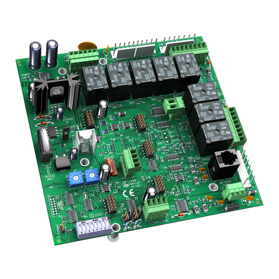
The RTU Open RTU OPEN....... . 44 controller may also require connection to a building network APPENDIX C —... - Page 3 76.8K baud (1, 2, and 4 ON) Recommended for all Protocol Selector *Remove SPT (temp input) BACnet, Modbus, or N2 i-Vu Open installations both for 0-5V SPT (common) (LON connection J15) SPT (offset input) Fig. 1 — RTU Open Control Module...
-
Page 4: Sensors And Accessories
Table 1 — RTU Open Controller Inputs and Outputs BACnet OBJECT CONNECTION PIN POINT NAME TYPE OF I/O CHANNEL DESIGNATION NAME NUMBER(S) DEDICATED INPUTS Space Temp / Zone Temp zone_temp J20-1 and 2 Analog Input 10 Supply Air Temperature sa_temp... - Page 7 Fig. 4 — Typical Factory Option Wiring - 50LC 14-26 Shown...
- Page 9 Fig. 6 — Typical Factory Option Wiring - 48TC 17-30 Shown...
- Page 10 Fig. 7 — Typical Factory Option Wiring - 50HC 17-28 Shown...
-
Page 11: Install Analog Sensors
BLU (SPT) conductor, twisted pair cable may be used. Below is the list of J20-1 the connections of the SPT to the RTU Open controller, refer to Fig. 8 and 9 for typical connections at the sensor. • J20-1 = temperature sensor input (SEN) •... -
Page 12: Co2 Sensor(S) (Iaq And Oaq)
NOTE: Communicating CO sensors and RH sensors can be aver- for electrical requirements and terminal locations. RTU Open aged if within the realm described. controller configurations must be changed after adding a CO sensor. See below and Fig. 12 for typical CO sensor wiring. -
Page 13: Relative Humidity Sensors
The current loop 0-10V power for the sensor is provided by the RTU Open controller as 24vdc. Refer to the instructions supplied with the RH sensor for electrical requirements and terminal locations. RTU Open controller configurations must be changed after adding a RH sensor. -
Page 14: Humidistat
If 24-vac is sensed, 48/50LC units) or Unit Control Board (UCB) (48/50FC(Q) then that is the gray wire that is connected to the RTU Open 04-07, 48/50GC(Q) 04-06). board at J2-7. The other is the signal for input 8, connect it to •... -
Page 15: Filter Status
The fan status accessory is a field-installed accessory. This ac- The RTU Open controller can be set to communicate on four cessory detects when the indoor fan is moving air. When in- different protocols: BACnet, Modbus, N2, and LonWorks. -
Page 16: Modbus
This accessory card is needed for LonWorks and has to be ordered and connected using the ribbon cable to plug J15 (see Fig. 19). The RTU Open controller baud rate must be set to 38.4k to com- Fig. 17 — RTU Open Controller Address Switches municate with the LonWorks Option Card. -
Page 17: Start-Up
POWER EXHAUST RELAY POWER This point allows the board's fan output to be manually turned The relay used by the RTU Open board to control power ex- On (Enable) and Off (Disable). Other test points that require haust is a dry contact which means it does not have 24vac. This... -
Page 18: Compressor 1 And Compressor 2 Test
NOTE: This point is only used when Continuous Occupied ing and purpose of each configuration point before changing it Exhaust = NO from the factory default value. Use the RTU Open controller Start-up Sheet during configuration; fill in changed values if UNIT changed from factory default. - Page 19 Fan Off Delay – Time delay in which the fan will continue run Comp 2 Service Alarm Timer – The timer set for the Com- after being commanded off. pressor 2 Runtime Alarm. After the number of hours set on this point is exceeded the corresponding alarm will be generated, Range = 10 to 300 sec and must be manually cleared in the maintenance menu after...
-
Page 20: Inputs
HP O/B Ctrl refers to a heat pump unit which requires revers- NOTE: For Inputs 1 and 2, if using Carrier air quality sensors do ing valve control. HP Y1/W1 Ctrl refers to a heat pump unit not use 24Vdc from RTU Open board. External 24Vdc power sup- whose reversing valve is built in to the cooling or heating call. - Page 21 Default = Disable (Enabled with Humidi-MiZer option) Factory Default = 5.2Vdc DCV Control – Enables demand controlled ventilation (DCV) Max VFD Output – The maximum VFD signal the RTU Open if valid CO sensor value is available and the unit has an econ- controller supplies to the VFD as a percentage of its range.
-
Page 22: Operation
This function applies if setting a local sched- put point for fan status. ule in the RTU Open controller or if applying the unit to an i-Vu ® Open Building Automation System or an Open zoning Cooling system. -
Page 23: Supply Fan
• Economizer is unavailable, or if the Economizer is active, The RTU Open controller supply fan may be configured for 1 mechanical cooling is available if the economizer is open of 3 Fan Modes: > 90% for at least 7.5 minutes, the SAT > [Minimum Cool- •... -
Page 24: Enthalpy Control
An outdoor air quality sensor may also be installed and termi- • Indoor Fan is ON for any unit with electric heat. nated at the RTU Open controller, but is not required. When an • Cool mode has not been active for 5 minutes. -
Page 25: Dehumidification
Demand Limit Fan Status If the RTU Open controller receives a level 1 (one degree off- Fan Status may be configured on any unused binary input set), 2 (two degree offset), or a 3 (4 degree offset) to the BAC- channel. -
Page 26: Filter Status
7 years with a minimum of 10,000 hours of back-up. When the RTU Open controller is part of a VVT system and When the RTU Open board is powered up, the battery is not being the controllers are wired together to form a network, the con- used. -
Page 27: Software Version
The higher the baud rate the more solid the LEDs will appear. See Table 3. Table 3 — LEDs The LEDs on the RTU Open controller show the status of certain functions If this LED is on... Status is... - Page 28 Table 4 — RTU Open Alarms BACnet Object ACTION TAKEN BY POINT NAME RESET METHOD PROBABLE CAUSE NAME CONTROL Safety Chain safety_alarm Immediate Shutdown Automatic Over load Indoor Fan or Electric Heater overheat Fire Shutdown fire_alarm Immediate Shutdown Automatic Smoke detected by smoke detector or...
-
Page 29: Alarms
ZS SENSOR are no configurations for this alarm; it is all based on field in- This alarm occurs if the ZS sensor wired to the RTU Open con- stalled wiring. This alarm will not occur if Fire Shutdown troller stops communicating with the controller. -
Page 30: Space Relative Humidity Sensor
SPACE RELATIVE HUMIDITY SENSOR ANALOG INPUT CONFIGURATION This alarm indicates the mA input at the associated channel This occurs if more than one analog input (inputs 1 and 2) is falls below 3.5 mA or rises above 21 mA, or the Network value configured for the same sensor. - Page 31 Range = Collect/Reset EQUIPMENT RUNTIME Default = Collect RTU Open controller monitors the supply fan and records the amount of time the unit has been operating. This value will con- HISTORICAL PERFORMANCE DATA tinue to accumulate runtime until Performance Data has been...
- Page 32 The serial numbers are unique and contain embedded information, for example OR2420042P: “Serial No: OR2YMCxxxP” “OR2” — These first three digits are unique to RTU Open and are used as an identifier. (Bar Code and Typed Number) “YM” — These two digits identify the last digit of the year and month (in hex, A=10/Oct) of manufacture.
- Page 33 APPENDIX A — USER INTERFACE MENUS Field Assistant Navigation Properties Equipment Status Configuration Unit Configuration Setpoints Alarm Configuration Service Configuration Maintenance Performance Alarms Linkage Fig. A — Field Assistant Navigation Chart Table A — User Interface Menus Access Level Equipment Field Assistant 3=ADMIN POINT NAME...
- Page 34 APPENDIX A — USER INTERFACE MENUS (CONT) Table A — User Interface Menus (cont) Access Level Equipment Field Assistant 3=ADMIN POINT NAME BACnet Object RANGE DEFAULT Touch Menu Menu 2=USER 1=No PW STATUS (cont) RTU Properties 3, 2, 1 Space Relative space_rh 0-100% Properties>...
- Page 35 APPENDIX A — USER INTERFACE MENUS (CONT) Table A — User Interface Menus (cont) Access Level Equipment Field Assistant 3=ADMIN POINT NAME BACnet Object RANGE DEFAULT Touch Menu Menu 2=USER 1=No PW INPUT CONFIGURATION RTU Properties Input 1 Function ai1_function 1=No Sensor IAQ Sensor Properties>...
- Page 36 APPENDIX A — USER INTERFACE MENUS (CONT) Table A — User Interface Menus (cont) Access Level Equipment Field Assistant 3=ADMIN POINT NAME BACnet Object RANGE DEFAULT Touch Menu Menu 2=USER 1=No PW SETPOINT RTU Properties Occupied Heating occupied_heat_setpoint 40-90 °F Properties>...
- Page 37 APPENDIX A — USER INTERFACE MENUS (CONT) Table A — User Interface Menus (cont) Access Level Equipment Field Assistant 3=ADMIN POINT NAME BACnet Object RANGE DEFAULT Touch Menu Menu 2=USER 1=No PW SERVICE CONFIGURATION RTU Properties Unit Type unit_type 1=Heat/Cool Heat/Cool (KC, TC, Properties>...
- Page 38 APPENDIX A — USER INTERFACE MENUS (CONT) Table A — User Interface Menus (cont) Access Level Equipment Field Assistant 3=ADMIN POINT NAME BACnet Object RANGE DEFAULT Touch Menu Menu 2=USER 1=No PW SERVICE CONFIGURATION (cont) Properties> RTU Properties Number of Heat Stages heat_stages 1=1 stage 0 (50 series electric Menu>...
- Page 39 APPENDIX A — USER INTERFACE MENUS (CONT) Table A — User Interface Menus (cont) Access Level Equipment Field Assistant 3=ADMIN POINT NAME BACnet Object RANGE DEFAULT Touch Menu Menu 2=USER 1=No PW SERVICE CONFIGURATION (cont) RTU Properties System Space AQ system_iaq Properties>...
- Page 40 APPENDIX A — USER INTERFACE MENUS (CONT) Table A — User Interface Menus (cont) Access Level Equipment Field Assistant 3=ADMIN POINT NAME BACnet Object RANGE DEFAULT Touch Menu Menu 2=USER 1=No PW UNIT MAINTENANCE (cont) RTU Properties Relative Humidity rh_source 1=N/A Properties>...
- Page 41 APPENDIX A — USER INTERFACE MENUS (CONT) Table A — User Interface Menus (cont) Access Level Equipment Field Assistant 3=ADMIN POINT NAME BACnet Object RANGE DEFAULT Touch Menu Menu 2=USER 1=No PW RUNTIME (MAINTENANCE) Supply Fan Runtime sfan_rntm xxxxx hr Properties>...
- Page 42 APPENDIX A — USER INTERFACE MENUS (CONT) Table A — User Interface Menus (cont) Access Level Equipment Field Assistant 3=ADMIN POINT NAME BACnet Object RANGE DEFAULT Touch Menu Menu 2=USER 1=No PW ALARMS (cont) RTU Properties 3, 2, 1 Wireless Batter Normal/Alarm Properties>...
- Page 43 APPENDIX A — USER INTERFACE MENUS (CONT) Table A — User Interface Menus (cont) Access Level Equipment Field Assistant 3=ADMIN POINT NAME BACnet Object RANGE DEFAULT Touch Menu Menu 2=USER 1=No PW AIRSIDE LINKAGE (cont) RTU Properties Unoccupied Cooling link_unocc_cl_stpt 75-130°F Properties>...
- Page 44 APPENDIX B — NETWORK POINTS LIST FOR RTU OPEN Table B — Network Points List for BACnet and Modbus BACnet Info Modbus Info Point Default Point Name Units BACnet BACnet Modbus Modbus Access Value Point Name Object ID Register Type...
- Page 45 APPENDIX B — NETWORKPOINTS LIST FOR RTU OPEN (CONT) Table B — Network Points List for BACnet and Modbus (cont) BACnet Info Modbus Info Point Default Point Name Units BACnet BACnet Modbus Modbus Access Value Point Name Object ID Register Type...
- Page 46 APPENDIX B — NETWORKPOINTS LIST FOR RTU OPEN (CONT) Table B — Network Points List for BACnet and Modbus (cont) BACnet Info Modbus Info Point Default Point Name Units BACnet BACnet Modbus Modbus Access Value Point Name Object ID Register Type...
- Page 47 APPENDIX B — NETWORKPOINTS LIST FOR RTU OPEN (CONT) Table B — Network Points List for BACnet and Modbus (cont) BACnet Info Modbus Info Point Default Point Name Units BACnet BACnet Modbus Modbus Access Value Point Name Object ID Register Type...
- Page 48 APPENDIX B — NETWORKPOINTS LIST FOR RTU OPEN (CONT) Table B — Network Points List for BACnet and Modbus (cont) BACnet Info Modbus Info Point Default Point Name Units BACnet BACnet Modbus Modbus Access Value Point Name Object ID Register Type...
- Page 49 APPENDIX B — NETWORKPOINTS LIST FOR RTU OPEN (CONT) Table B — Network Points List for BACnet and Modbus (cont) BACnet Info Modbus Info Point Default Point Name Units BACnet BACnet Modbus Modbus Access Value Point Name Object ID Register Type...
- Page 50 APPENDIX B — NETWORKPOINTS LIST FOR RTU OPEN (CONT) Table B — Network Points List for BACnet and Modbus (cont) BACnet Info Modbus Info Point Default Point Name Units BACnet BACnet Modbus Modbus Access Value Point Name Object ID Register Type...
- Page 51 APPENDIX B — NETWORKPOINTS LIST FOR RTU OPEN (CONT) Table C — Network Points List for N2 and LonWorks (cont) LonWorks Point Default Point Name Units N2 Network N2 Network Access Value SNVT Type SNVT Name Point Type Point Setpoint °F...
- Page 52 APPENDIX B — NETWORKPOINTS LIST FOR RTU OPEN (CONT) Table C — Network Points List for N2 and LonWorks (cont) LonWorks Point Default Point Name Units N2 Network N2 Network Access Value SNVT Type SNVT Name Point Type Point Indoor Air Quality CO2 (ppm)
- Page 53 Equipment Touch Installation and Setup Guide. NOTE: The System Touch™ interface when connected to the RTU Open controller over the BACnet MS/TP network will pro- vide the same screens and function as the Equipment Touch. STANDBY Fig.
- Page 54 APPENDIX C — EQUIPMENT TOUCH NAVIGATION SCREENS (CONT) RTU OPEN PROPERTIES SHOW/HIDE CONFIGURATION Fig. F — RTU Properties Menu Screen Fig. G — Show/Hide Configuration Screen Navigates to the Property pages. You can configure Show/Hide conditions for values on the fol-...
- Page 55 RTU OPEN CONTROLLER START-UP SHEET RTU Model Number: Date: RTU Serial Number: Performed by: RTU Open Software Version: Company: Protocol and Baud Rate: Network Address: CONFIGURATION POINTS POINT NAME BACnet OBJECT RANGE DEFAULT ENTRY SETPOINT Occupied Heating Setpoint occupied_heat_setpoint 40-90 °F...
- Page 56 CONFIGURATION POINTS (CONT) POINT NAME BACnet OBJECT RANGE DEFAULT ENTRY UNIT CONFIGURATION (cont) S Fan Service Alarm Timer sfan_service_hrs 0-9999 hr Supply Fan Service Alarm sfan_service_hrs 0-9999 hr Timer Comp 1 Service Alarm comp1_service_hrs 0-9999 hr Timer Comp 2 Service Alarm comp2_service_hrs 0-9999 hr Timer...
- Page 57 CONFIGURATION POINTS (CONT) POINT NAME BACnet OBJECT RANGE DEFAULT ENTRY INPUT CONFIGURATION (cont) Space sensor type spt_type 1=T55 None 2=T56 (use for T59) 3=SPT Sensor 4=None 5=ZS Sensor ZS Sensor Binder zs_binder Rnet/Unused Rnet ZS Zone Temp zs_zone_temp Zone Temp (1-5) Main ZS Sensor ZS Zone Humidity zs_zone_humidity...
- Page 58 CONFIGURATION POINTS (CONT) POINT NAME BACnet OBJECT RANGE DEFAULT ENTRY SERVICE CONFIGURATION (cont) Number of Heat Stages heat_stages 1=1 stage 0 (50 series electric no heat 2=2 stages units) 3=0 stage 1 (All Heatpumps, Low Nox units, single phase gas units) 1 (KC/TC04-09 low and KC/TC05-07 med heat...
- Page 59 CONFIGURATION POINTS (CONT) POINT NAME BACnet OBJECT RANGE DEFAULT ENTRY SERVICE TEST Service Test test_enable Disable/Enable Disable Fan Test fan_test Disable/Enable Disable High Speed Fan Test hi_spd_test Disable/Enable Disable Compressor 1 Test comp1_test Disable/Enable Disable Compressor 2 Test comp2_test Disable/Enable Disable Heat 1 Test heat1_test...
- Page 60 © Carrier Corporation 2020 Manufacturer reserves the right to discontinue, or change at any time, specifications or designs without notice and without incurring obligations. Catalog No. 04-53480262-01 Printed in U.S.A. Form 48-50-RTU-01T Pg CL-6 1-20 Replaces: 48-50LHTCQ-01T...
Need help?
Do you have a question about the RTU Open and is the answer not in the manual?
Questions and answers