Advertisement
Quick Links
AIRMOVER
Square Cased Fans
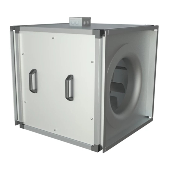
DSM (mixed flow)
Fig. 1 DSM unit shown in avertical application.
IMPORTANT
The installation must be carried out by qualified personnel in
accordance with the appropriate authority and conforming to all
statutory and governing regulations.
Contents
Introduction ............................................................. 1
Description ............................................................... 1
Handling ................................................................... 1
Installation ............................................................... 1
Mounting arrangements ........................................ 4
Dimensions ............................................................... 6
Motor Information ................................................ 8
Routine Maintenance ............................................. 9
Replacement of parts .............................................. 9
Speed Controls (single phase)............................... 11
Speed Controls (three phase)................................ 11
Certification ............................................................ 13
W
ARNING
1. D
O NOT REVERSE IMPELLER DIRECTION FOR
OPERATION AS THE PERFORMANCE OF THE UNIT
.
IS DRASTICALLY REDUCED
2. D
O NOT ALTER THE BLADE ANGLE OF THE
IMPELLER WITHOUT THE PERMISSION OF
T
HE ABOVE MAY INVALIDATE YOUR WARRANTY
!
N
A
.
U
IRE
Installation
and Maintenance
NuAire Limited
Western Industrial Estate Caerphilly,
CF83 1XH United Kingdom
Telephone 029 2088 5911
Facsimile No. 029 2088 7033
Email: info@nuaire.co.uk
www.nuaire.co.uk
Introduction
NuAire Airmover DSM square cased fans incorporate
mixed flow impellers.
Casings are manufactured in galvanised steel with
propriety flanges fitted to allow connection to
ductwork. A full width access panel allows inspection
of the motor and impeller whilst still in duct.
A full range of matching ancillaries is available
including Silencers, Fan Guards, Resilient Mounting
Kits, Speed Controls and Flexible Connectors.
All NuAire DSM units are tested to BS848 in our BSI
approved laboratories. This ensures all technical data is
accurate, which means that units can be specified with
confidence
Description
The units are coded DSM followed by the impeller
diameter in mm ie. DSM315
Silencers, flexible connectors, resilient mountings and
guards are supplied as optional extras. Short and long
versions of the silencer (SIL-S) & (SIL-L) are
available for each size. Speed controls are available for
most units.
Handling
Equipment must be handled carefully to avoid damage
or distortion. Except for the smallest 315 size , units are
provided with four lifting eyes. If spreaders are used,
they should be positioned as near the end flanges as
possible and in such a way that slings or webbing do
not bear on the casing. Webbing, rope of any other
material must not be passed through units for lifting
purposes.
Installation
General
The design and provision of complimentary ductwork
supports, etc., is the responsibility of others. Adequate
space, however, must be provided around the
unit/silencer combination to enable it to be easily
removed from the ductwork when required. It is also
important that the fan unit is mounted so that it is
readily accessible. Provide adequate space around the
unit to allow for the removal and the replacement of
the impeller and motor via the access panel.
Leaflet No. 670985
OCTOBER 2001
1
Advertisement

Related Manuals for NuAire AIRMOVER DSM Series


Summary of Contents for NuAire AIRMOVER DSM Series
-
Page 1: Table Of Contents
Silencers, Fan Guards, Resilient Mounting Kits, Speed Controls and Flexible Connectors. All NuAire DSM units are tested to BS848 in our BSI approved laboratories. This ensures all technical data is accurate, which means that units can be specified with Fig. - Page 2 Installation and Maintenance AIRMOVER DSM UNITS Installation (continued) Prior to installation, thoroughly clean the fan unit, paying particular attention to its interior. Be particularly thorough if the unit has been lying idle for several weeks on an active building site or in a dust-laden environment. A build up of cement dust, for example, could prove to be very damaging, especially if throughput air were to be damp.
- Page 3 Switch isolation device (by others) to the ON position NOTE: If a NuAire speed control is fitted, this can also be used to Some units may not have thermal protection fitted as switch the airmover OFF and ON. Note that the unit standard.
-
Page 4: Installation
Installation and Maintenance AIRMOVER DSM UNITS Installation Vertical Mounting Flow Flow Free air space Free air space Free air space Fan unit Free air space Vertical mounting of a fan or fan /silencer combination where a silencer is NOT positioned above the fan. Left-hand view shows arrangement when flow is upwards as shown, right hand view arrangement when flow is downwards. - Page 5 Installation and Maintenance AIRMOVER DSM UNITS Mounting Foot details Note Four mounting feet are supplied with each unit or silencer, see main dimension drawings. M8 fixing screws are included. M8 unit fixings supplied Resilient mountings details DAV 34 & DAV 35 Dimensions (mm) Code DAV 1...
-
Page 6: Dimensions
Installation and Maintenance AIRMOVER DSM UNITS Dimensions AIRFLOW D sq. (ctrs) 4 Holes 'E' dia. A sq. (internal) Mounting feet (supplied) DSM Mixed flow unit Dimensions (mm) Weight Size (kg) E dia. DSM 315 DSM 400 20.5 DSM 500 DSM 630 DSM 800 DSM 1000 1000... - Page 7 Installation and Maintenance AIRMOVER DSM UNITS Dimensions (continued) Dimensions (mm) Resilient Note: Mounting feet Mountings supplied with Code (typical) see page 5 for DSA units. DAV 1 further information DAV 2 DAV 3 DAV 4 DAV 5 DAV 6 Wire Guard Dimensions (mm) Mild steel mesh guard.
-
Page 8: Motor Information
Installation and Maintenance AIRMOVER DSM UNITS Motor Information ELECTRICAL General Electrical 1 Phase (230V) 3 Phase (400V) Unit Speed Power Code (amps)(amps) DSM315-11 1300 0.010 0.37 0.48 DSM315-21 1398 0.015 0.33 0.39 DSM315-31 1440 0.049 0.47 0.78 DSM315-41 2580 0.065 0.86 DSM315-51 2580... -
Page 9: Routine Maintenance
Installation and Maintenance AIRMOVER DSM UNITS Routine Maintenance Replacement of Parts Isolation Isolation Before commencing, make sure that the DuctMaster and Before commencing, make sure that the DuctMaster is speed control, if fitted, are externally isolated from the externally isolated from the electrical supply electrical supply. - Page 10 Installation and Maintenance AIRMOVER DSM UNITS Replacement of Parts (continued) Impeller Mixed Flow Impeller (removal). Size 315. Slacken two grub screws in the boss and withdraw the impeller from the motor shaft. Overlap Size 400-1250. Impellers are retained by a taper lock Dimension ‘A’...
-
Page 11: Speed Controls (Single Phase)
Installation and Maintenance AIRMOVER DSM UNITS Speed Controls (single phase) Electronic ESC1-3A / 6A Single phase speed controls are fixed through holes in the base which are accessible on removal of the cover. Fixing hole Bases are provided with 20mm & 25mm knockouts positions Cable access Cover... - Page 12 Installation and Maintenance AIRMOVER DSM UNITS Wiring Diagrams DSM Units Note: For general guidance only. Specific motor wiring information is included with individual fan units. Single Speed 1 phase Single Speed 3 phase T1 T2 T1 T2 U1 V1 W1 unit unit Note:...
- Page 13 Caerphilly, Mid Glamorgan, CF83 1XH. United Kingdom. Telephone: 029 2088 5911 Fax: 029 2088 7033 DECLARATION OF INCORPORATION Email: info @ nuaire.co.uk & INFORMATION FOR SAFE www.nuaire.co.uk OCTOBER 1998 INSTALLATION, OPERATION & MAINTENANCE We declare that the machinery named below is intended to be assembled with other components to constitute a system of machinery.
- Page 14 Caerphilly, Mid Glamorgan, CF83 1XH. United Kingdom. Telephone: 029 2088 5911 Fax: 029 2088 7033 DECLARATION Email: info @ nuaire.co.uk www.nuaire.co.uk OF CONFORMITY OCTOBER 1998 We declare that the machine named below conforms to the requirements of EC Council Directives relating to Electromagnetic Compatibility and Safety of Electrical Equipment.
- Page 15 To be read in conjunction with the relevant Product Documentation (see 2.1) GENERAL The equipment referred to in this Declaration of Incorporation is supplied by NuAire to be assembled into a ventilation system which may or may not include additional components.
- Page 16 A team of Engineers and technicians is available to provide pre and post order support. We are on hand to provide help and advice from the most basic use of any NuAire equipment to the more complex applications, maximising on the versatility of our SMART and NetLink control products.
Need help?
Do you have a question about the AIRMOVER DSM Series and is the answer not in the manual?
Questions and answers