Table of Contents
Advertisement
Quick Links
®
SYSTIMAX
Solutions
SYSTIMAX 360
General
™
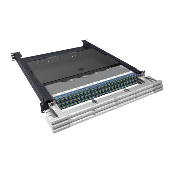
The SYSTIMAX 360
ultra high-density (UHD) shelf, 3603D-1U-UP, is a 19-inch (483mm) wide fiber optic shelf
that provides three positions for InstaPATCH
allows access to the high-density connector patching field. The shelf provides a secure, enclosed slack trunk
cable storage and features a removable cover. It is intended for indoor use, but may be used outdoors in a
suitable protective enclosure. The shelf is available as an empty shelf where modules or panels are not included
and must be ordered separately or in preloaded versions that include modules (in ALPHA or BETA orientation) or
panels. Additional shelf configurations provide for fusion splicing when using LC pass-thru panels.
Ordering information is listed below:
Material ID
760110999
3603D-1U-UP
760136457
3603D-1U-144LC-LS-A
760136465
3603D-1U-144LC-LS-B
760136432
3603D-1U-144LC-SM-A
760136440
3603D-1U-144LC-SM-B
760136473
3603D-1U-72MPO
760149054
3603D-1U-144LC-TS-DP
760149062
3603D-1U-144LC-LS-DP
™
SYSTIMAX 360
www.commscope.com
™
Ultra High-Density Shelf Instructions
®
Part No.
Fiber shelf, 1U, UHD, empty
3603D-1U-UP UHD shelf with three 3603M-48LC-LS UHD modules in
ALPHA orientation
3603D-1U-UP UHD shelf with three 3603M-48LC-LS UHD modules in
BETA orientation
3603D-1U-UP UHD shelf with three 3603M-48LC-SM UHD modules in
ALPHA orientation
3603D-1U-UP UHD shelf with three 3603M-48LC-SM UHD modules in
BETA orientation
3603D-1U-UP UHD shelf with three 3603P-24MPO UHD panels
Splice shelf with three TeraSPEED
Splice shelf with three LazrSPEED
3D-UHD Shelf in Closed Position and Open Position for Patch Cord Access
© 2013 CommScope, Inc. All rights reserved
360 UHD modules or UHD panels. A unique pivoting feature
Description
Instruction Sheet 860479229
Issue 7, May 2013
®
(SM) LC pass-thru panels
®
LC pass-thru panels
Page 1 of 15
Advertisement
Table of Contents

Subscribe to Our Youtube Channel
Related Manuals for CommScope SYSTIMAX 360

Summary of Contents for CommScope SYSTIMAX 360
- Page 1 (SM) LC pass-thru panels ® 760149062 3603D-1U-144LC-LS-DP Splice shelf with three LazrSPEED LC pass-thru panels ™ SYSTIMAX 360 3D-UHD Shelf in Closed Position and Open Position for Patch Cord Access © 2013 CommScope, Inc. All rights reserved Page 1 of 15...
-
Page 2: How To Contact Us
1-800-344-0223. Outside the United States, contact your local account representative or Authorized Business Partner. Within the United States, report any missing/damaged parts or any other issues to CommScope Customer Claims at 1-866-539-2795. Outside the United States, contact your local account representative or Authorized Business Partner. Tools Required •... - Page 3 860479229 Issue 7, May 2013 Separately Orderable Modules and Panels Material ID Part No. Description ® 760111013 360-3M-4MPM1-48LC-LS InstaPATCH 360 UHD LazrSPEED MM module, 48F LC ® 760111039 360-3M-4MPM1-48LC-TS InstaPATCH 360 UHD TeraSPEED SM module, 48F LC 760111153 3603P-24MPO...
-
Page 4: Connector Cleaning
860479229 www.commscope.com Instruction Sheet Connector Cleaning • InstaPATCH 360 UHD modules are pre-terminated, with protective spring-loaded shutters (LC) installed on all adapters. Connectors internal to the adapters are clean when purchased. • Clean cable and jumper connectors per manufacturer’s recommendations prior to connection to the shelf. - Page 5 860479229 Issue 7, May 2013 8-32 nuts with lockwashers (4 places) 3603D-UDH-1U shelf 8-32 screws with lockwashers (4 places) Front Rear stabilizer 12-24 brackets screws (8 places) 2 Post Rack Mount Step 2A – Route and Secure Cable to Shelf...
- Page 6 860479229 www.commscope.com Instruction Sheet 1. Fully extend sliding shelf to front of rack. Note: The shelf sliding mechanism incorporates two sets of position stops: one for normal operation and a second for installation purposes. When pulling the shelf out, it will stop at the first operation cam stop.
- Page 7 860479229 Issue 7, May 2013 Method B 1. Working back from where cable enters shelf (at cable gland), carefully dress cable toward opposite side of shelf. Route cable over slide rail, taking care to not exceed minimum bend radius.
-
Page 8: Step 3 - Module Configuration
860479229 www.commscope.com Instruction Sheet If cables enter shelf from opposite sides, loosely secure them together at the point where the cables meet in center, using a hook-and-loop strip as shown. 2. Verify shelf retracts and extends fully before proceeding to next step. - Page 9 860479229 Issue 7, May 2013 Step 4 – Mount Modules/Panel in Shelf Before installing modules/panels be sure any pre-installed cable sub-units are behind pivot mount panels and provide enough clearance for panel installation. Module/Panel Installation 1. Insert panel/module at an angle into one...
-
Page 10: Step 6 - Install Cover
860479229 www.commscope.com Instruction Sheet Step 5 – Connect Fiber Cables to Modules 1. Store slack fiber cable in shelf as shown behind modules in loops. Important: Leave sufficient slack in fiber cable to plug MPO connectors Fiber into modules leave... - Page 11 860479229 Issue 7, May 2013 Step 7 – Install Patch Cords with Cord Management Sleeve The 360G2 UHD shelf provides a unique patch cord access feature of pivoting panels/modules that allow the product to achieve a very high density of fiber connection. The top and middle panels pivot up and slide slightly back into up locking positions.
- Page 12 860479229 www.commscope.com Instruction Sheet Instructions for Fusion Splicing Splice Tray Features Hole provided for plastic hardware Fiber retention gate (4 positions) (2 positions) Fiber entry/exit openings (8 positions) Hole provided for Cover retention optional mounting scheme snaps (6 positions) (4 positions)
- Page 13 860479229 Issue 7, May 2013 Step 8 – Build Up Tray Shelf OSP cable Equipment rail Buffer tube Work surface Splice tray Buffer tube Cable tie Splice sleeve Pigtails WARNING Take proper precautions to avoid damaging fiber while routing into shelf and splice tray.
- Page 14 860479229 www.commscope.com Instruction Sheet • Install splice sleeves into lower position of holders by firmly pressing them down into retention features with 2 index fingers. One finger is sufficient for placing sleeves into the upper (stacked) position. Use orange stick or similar device to remove sleeves for repairs.
- Page 15 860479229 Issue 7, May 2013 Step 10 – Building Up and Stacking Trays Top cover Snap rivet plunger 3-tray stack Snap rivet grommet Note: Do NOT remove paper backing from adhesive on bottom of additional trays. 1. Align 4 holes on base (provided for plastic hardware) with 4 holes on elevated platforms of previous tray.
Need help?
Do you have a question about the SYSTIMAX 360 and is the answer not in the manual?
Questions and answers