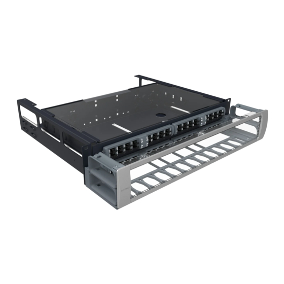
Summary of Contents for CommScope SYSTIMAX InstaPATCH 360
- Page 1 Design Guide SYSTIMAX InstaPATCH ® ® Traffic Access Point (TAP) Solution www.commscope.com...
-
Page 2: Table Of Contents
Contents Introduction How Does a TAP Work? The TAP Ecosystem InstaPATCH 360 TAP Module Family InstaPATCH 360 TAP Fan-out Array Cords InstaPATCH 360 TAP Pre-terminated Fiber Cables Traffic Monitoring System Fiber Cabling System Design with TAPs Example 1—10Gbps Ethernet Example 2—8Gbps Fibre Channel Optical Channel Loss Evaluation with TAPs Loss Evaluation of Main Traffic Channels Loss Evaluation of Shorter Monitor Channels... -
Page 3: Introduction
This design guide will help you understand and design fiber cabling systems using CommScope SYSTIMAX... -
Page 4: The Tap Ecosystem
Figure 2 shows some examples of the CommScope TAP family, including combinations of 12-fiber or 24-fiber, MMF or Single-mode fiber (SMF), and 70/30 or 50/50 split ratio. -
Page 5: Instapatch 360 Tap Fan-Out Array Cords
The MMF TAPs are designed to operate at 850nm wavelength. The MMF TAP can be deployed with bend-insensitive or traditional OM3 or OM4 fiber cabling. The single-mode fiber TAPs are optimized for operation at 1310nm wavelength. The designed split ratios of the TAP modules are selected for compatibility with the supported applications. -
Page 6: Fiber Cabling System Design With Taps
(e.g. 8G Fibre Channel or 10G Ethernet), and the monitor equipment capability. Fortunately the SYSTIMAX InstaPATCH 360 Fiber TAP Solution Performance Specification provides channel topology limits that account for many of these factors to simplify the design process. The following two sections provide practical design examples using this Performance Specification for a 50/50 MMF TAP solution and a 70/30 MMF TAP solution. - Page 7 Figure 4. Retrofit example: 10GE channel with 50/50 TAP module replacing MPO/LC module at central cross connect A quick check of the Performance Specification reveals that the 10GBASE-S power budget supports both 50/50 and 70/30 split ratios for the main channel. The ability to support a 50/50 split ratio also permits the monitor equipment to use minimally standards-compliant transceivers, and therefore the monitor channels may also be designed using the same topology limit tables as the main channel.
-
Page 8: Example 2-8Gbps Fibre Channel
Table 1 is an extract from the SYSTIMAX InstaPATCH 360 Fiber Tap Solutions Performance Specifications —Volume Five for 10GBASE-S on LazrSPEED 550 and the 50/50 split ratio TAP. - Page 9 LC connections (the connections to the active equipment are not counted), and the channel length is 110m. Table 3 is an extract from the SYSTIMAX InstaPATCH 360 Fiber Tap Solutions Performance Specifications—Volume Five for 8GFC on LazrSPEED 550 and the 70/30 split ratio TAP.
-
Page 10: Optical Channel Loss Evaluation With Taps
The longer monitor channel has three low-loss MPO connections, one low-loss LC connection, and the length is 110m. The shorter monitor channel has one low-loss MPO connection, one low-loss LC connection, and the length is 20m. Follow the procedure of Section 5 to provide the monitor company the information they need to evaluate your channel design for compatibility with their equipment. -
Page 11: Loss Evaluation Of Shorter Monitor Channels
Figure 6. Illustration of the main traffic channel signal paths Loss Evaluation of Shorter Monitor Channels Figure 7 shows the monitor channel signal path from the end closest to the monitor. The LC/LC equipment cord is 10m long, and the fan-out array cord connected to the monitoring port is also 10m long. -
Page 12: Loss Evaluation Of Longer Monitor Channels
Loss Evaluation of Longer Monitor Channels Figure 8 shows the monitor channel signal path from the end farthest from the monitor. The trunk cable is 80m long. Both LC/LC equipment cord and fan-out array cord are 10m long. Using SYSTIMAX Solutions Link Loss Calculator, Version 7.1 plug in the following factors: select a 30 percent TAP, three low-loss MPO connections, one low-loss LC connection, and 100m “LazrSPEED with InstaPATCH @ 850nm”... -
Page 13: Ordering Information
Ordering Information InstaPATCH 360 TAP solution can be ordered by contacting CommScope Sales. Please visit the CommScope eCatalog at the following link. http://www.commscope.com/Product-Catalog/Enterprise/Product/Fiber/ MATERIAL ID PRODUCT CODE DESCRIPTION 760188284 360TM-12LC-LS-70:30 TAP module, 12F duplex LCs, OM4, 70/30 signal split (Main/TAP) - Page 14 MATERIAL ID PRODUCT CODE DESCRIPTION 760196501 360TM ARRAY, PLNM, LS, TAP fan-out cables, MPO (unpinned), 12 MP(f)-LC(s), M05 simplex LCs, OM4, plenum, 5m 760196519 360TM ARRAY, PLNM, LS, TAP fan-out cables, MPO (unpinned), 12 MP(f)-LC(s), M06 simplex LCs, OM4, plenum, 6m 760196527 360TM ARRAY, PLNM, LS, TAP fan-out cables, MPO (unpinned), 12...
-
Page 15: References
References 1. SYSTIMAX InstaPATCH 360 Traffic Access Point (TAP) Solutions Performance ® ® Specifications, Vol.5, June 18, 2014. 2. SYSTIMAX Solutions—Link Loss Calculator, Version 7.1. 3. IEEE 802.3, “IEEE standards for Ethernet”, December 2012. 4. ANSI/INCITS 479-2011, “Information technology—Fibre Channel—Physical Interfaces— 5 (FC-PI-5)”, November 2011. - Page 16 All trademarks identified by ® or ™ are registered trademarks or trademarks, respectively, of CommScope, Inc. This document is for planning purposes only and is not intended to modify or supplement any specifications or warranties relating to CommScope products or services.


Need help?
Do you have a question about the SYSTIMAX InstaPATCH 360 and is the answer not in the manual?
Questions and answers