
Subscribe to Our Youtube Channel
Related Manuals for BEKA BA384G


Summary of Contents for BEKA BA384G
- Page 1 BA384G and BA384E Intrinsically safe Two input Rate Totaliser Issue 5 Issue: 5 July 2019...
-
Page 2: Table Of Contents
Source of output pulse: 5ource scale card. Divide output pulse frequency: divide Define output pulse width: duration 8.9 Stored pulses The BA384G and BA384E are CE marked to show compliance with European Explosive Atmospheres Directive 2014/34/EU and European EMC Directive 2014/30/EU. - Page 3 9. CONFIGURATION EXAMPLE Appendix 1 Dust certification Configuration procedure Appendix 2 IECEx certification 10. MAINTENANCE 10.1 Fault finding during commissioning Appendix 3 ETL and cETL certification 10.2 Fault finding after commissioning 10.3 Servicing Appendix 4 BA384E Rate Totaliser 10.4 Routine maintenance 10.5 Guarantee 10.6 Customer comments 11.
-
Page 5: Description
The main sections of this instruction manual total display is incremented. describe the BA384G, but they also apply to the BA384E. Details of the BA384E mounting and following... -
Page 6: Initialisation
Controls Each time power applied to a BA384G The BA384G is controlled and configured via four initialisation is performed. After a short delay the front panel push buttons. In the totalising mode i.e. following display sequence occurs: when the instrument is displaying rate and total flow... -
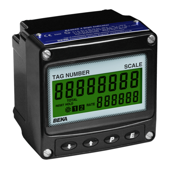
Page 7: Displays
Displays 2.3.1 Display over-range The BA384G has two digital displays and associated Over-range of the upper eight digit display or the annunciators, plus a flow indicator as shown on the lower six digit display is indicated by all the digits front cover of this manual. -
Page 8: Intrinsic Safety Certification
Totaliser is installed in Zone 1 or in Zone 2. This compliance with the European ATEX Directive for allows the BA384G to be installed in all gas Zones Group II, Category 1G equipment, Ex ia IIC T5 Ga and to be used with most common industrial gases equipment. -
Page 9: Pulse Input Terminals
2-wire proximity detector in a simple apparatus. turbine flowmeter, fitting an external link between terminals 3 & 4 of the BA384G for input A and b. The flowmeter and associated wiring can between terminals 7 & 8 for input b, connects an withstand a 500V rms insulation test to earth. -
Page 10: Remote Reset Terminals
Remote reset terminals The BA384G total display may be reset to zero by connecting the external reset terminals RS1 and RS2 together for more than one second. The two reset terminals have the following input and output... -
Page 11: System Design For Hazardous Areas
BA384G. Terminals 2, 6, 10 and RS2 of the BA384G Rate Totaliser are internally connected together as shown in Fig 1. If any of these terminals are earthed, as shown in Figs 2 &... -
Page 12: Pulse Inputs
2.1V when terminals 7 & 8 are linked terminals 5 & 6 or 9 &10 providing the flowmeter is located in the same hazardous area as the BA384G, and the flowmeter and associated wiring can 4.1.2 Pulse inputs withstand a 500V rms insulation test to earth. -
Page 13: Use With Galvanic Isolators
Alternatively flowmeters may be located in the safe area. Fig 5 shows how additional galvanic isolators A BA384G may also be remotely reset from the safe are used to transfer the pulse signal to the BA384G area. Any switch may be used but a Zener barrier... -
Page 14: Pulse Inputs
4.2.2 Pulse inputs As shown in Figs 4 and 5 both BA384G inputs can be directly connected to hazardous area flowmeters, or to safe area flowmeters via isolators. Galvanic isolators are not required in series with the input if an intrinsically safe flowmeter is located within the same hazardous area as the BA384G. -
Page 15: 2-Wire Proximity Detector Input
BA384G input parameters required. Ci and Li which are small and can often be ignored. A BA384G may also be remotely reset from the safe The flowmeter must be located within the same area. Any switch may be used but a galvanic... -
Page 16: Installation
5. INSTALLATION Location The BA384G Rate Totaliser is housed in robust IP66 glass reinforced polyester (GRP) enclosure incorporating an armoured glass window and stainless steel fittings making it suitable for exterior mounting in most industrial on-shore and off-shore installations. The Rate Totaliser... -
Page 17: Emc
The BA384G complies with the requirements of the European EMC Directive 2014/30/EU. For specified immunity all wiring should be in screened twisted pairs, with the screens earthed at one point in the safe area. Units of measurement and tag marking on scale card. -
Page 18: Configuration And Calibration
Clip-off for input A* CLP . oFF-A 0000. 0 calibrated to display the same engineering units. When the BA384G Rate Totaliser is in the totalising Local total reset Clr tot mode the following displays can be selected using Local grand total reset Clr Gtot the &... -
Page 22: Accessing Configuration Functions
Configures the Rate Totaliser input to changes will not be stored. When configuring a accept one of six types of input: BA384G Rate Totaliser it is therefore advisable to Open collector ● oP. C oL occasionally return to the totalising mode to ensure Voltage pulse <1 >3V... - Page 23 Display Summary of function Display Summary of function Decimal points dEbounCE Defines the position of the decimal point Defines level input de-bounce in both the rate and total displays. applied to the pulse input to prevent See section 6.12 false counting: dEFAuLt HEAVY Input A flowmeter K-factor *...
- Page 24 Display Summary of function Display Summary of function Timebase External reset t-bA5E e clr Selectable multiplier allowing flow rate This function defines which totals are to be displayed in units per second, per reset to zero when terminals RS1 and minute or per hour.
-
Page 25: Rate Totaliser Function: Function
6.4 Rate Totaliser function: FunCtion One of following six types may be selected for each This function determines whether the BA384G Rate input: Totaliser has a standard linear function, or if the two Switching separate adjustable sixteen segment linearisers, one... -
Page 26: Display Update Interval: Update
The Rate Totaliser’s maximum counting frequency 6.9 Composite display: Count depends upon the debounce level selected, the The BA384G can produce a composite rate and total shape of the input pulse and its amplitude. display from the sum or difference of Input-A and following table assumes a square wave input and is Input-b. -
Page 27: Position Of Decimal Points: Dp
6.13 Flowmeter K-factor: FACtor-A * Display The rate totaliser pulse input A is divided by selected Lower display di5p-2 setting in FACtor-A, which is adjustable between 0.0001 and using the configuration menu. & or * 99999. For flow applications FACtor-A should be buttons in set to the K-factor of the flowmeter connected to the tota-... -
Page 28: Rate Scale Factor: 5Cale. R -A
6.15 Rate scale factor*: 5CALE . r-A 6.17 Display filter*: FiLtEr-A 5CALE . r-A is a dividing factor adjustable between The digital display filter associated with each input 0.0001 and 99999 that enables the flow rate to be independent adjustable parameters displayed in the required engineering units. -
Page 29: Clip-Off: Clp. O Ff-A
HOLD annunciator will be the grand total display to zero with the BA384G in activated. The flow indicator will continue to rotate... -
Page 30: External Reset: E Clr
6.22 External reset: E clr 6.24 Security code: CodE The BA384G total displays can be remotely reset to Access to the instrument configuration menu may be zero when terminals RS1 and RS2 are connected protected by a four digit alphanumeric security code together for more than one second. -
Page 31: Linearisers
7. LINEARISERS 7.1 Flowmeter specification Flowmeters are usually supplied with a calibration The BA384G Rate Totaliser can produce accurate certificate specifying the average K-factor and the results when used with flowmeters having K-factors flow range over which it applies. For use over... -
Page 33: Add A Segment: Add
7.3 Copy A lineariser configuration successive breakpoints must be monotonic to b lineariser: Copy A2b i.e. the pulse input frequency must increase When both inputs of the BA384G Rate Totaliser are with breakpoint number. See 7.8 connected to separate flowmeters with the same non-linearity,... -
Page 34: Remove A Segment: Del
7.5 Remove a segment: dEL ( which will reveal the current input frequency with dEL is a sub-menu in the FACtor-A function that one digit flashing. The value of the flashing digit enables any segment to be removed from the may be changed by pressing the &... -
Page 35: Lineariser Error Messages
When L_FACtor for all of the segments has been entered, return to the FACtor-A prompt in the The BA384G Rate Totaliser has an opto-isolated configuration menu by operating the ) push button pulse output with the following electrical parameters: twice. -
Page 36: System Design
8.2 System design 8.3 Configuration The Rate Totalisers pulse output is a passive circuit The pulse output sub-menu is accessed via the i.e. unpowered open collector, but it is totally isolated PuL5E oP function in the configuration menu. The from all other Rate Totaliser circuits. Subject to pulse output sub-menu allows the source of the complying... -
Page 37: Enable Pulse Output: Enbl
8.5 Enable pulse output: Enbl 8.7 Divide output pulse frequency: diVidE This function allows the pulse output to be disabled When the output pulse is derived from the least or enabled without altering any of the pulse output significant digit of the composite total, the output parameters. -
Page 38: Stored Pulses
K-factor of 105 pulses per litre with a magnetic pick- 0. 1 off output. 0. 5 The BA384G is required to display rate of flow in 2. 5 imperial gallons per hour with a resolution of one gallon and total flow in cubic metres with a maximum total of 100000 and a resolution of 0.01 cubic... - Page 39 Using the & or * button select Step 7 Lower display dEbouncE from the sub-menu and press Using the & or * button select di5P-2 (. Using the & or * button select in the configuration menu and press dEFAuLt which will provide moderate ( to select if the lower display function.
- Page 40 Finally, enter the new figure and return to This should be changed to 4.5461 using the FACtor-A prompt in the configuration the & or * push button to adjust the menu by pressing ). The output from flashing digit and the ( button to FACtor-A will now be in litres which may transfer control to the next digit and to be scaled to produce required rate and...
- Page 41 In this example the operator is required to reset the total displays but not the composite grand total display when the BA384G Rate Totaliser is in the totalising mode.
-
Page 42: Maintenance
CLr . Gtot prompt in 10.1 Fault finding during commissioning the configuration menu. If a BA384G fails to function during commissioning the following procedure should be followed: See 6.23 Step 17 Define the security code... -
Page 43: Fault Finding After Commissioning
Instruments which fail within the guarantee period ENSURE PLANT SAFETY BEFORE should be returned to BEKA associates or your local STARTING MAINTENANCE BEKA agent. It is helpful if a brief description of the fault symptoms is provided. Live maintenance permitted... -
Page 44: Accessories
This may result in an alarm being delayed for up to half a second after the rate or total has exceeded The BA384G can also be supplied with a blank or the setpoint. custom laser engraved stainless steel legend plate - see Fig 7. - Page 45 Adjusts the alarm hysteresis. Only 11.3.3 Configuration and adjustment available on a rate alarm. When a BA384G is supplied with alarms the See section 11.3.9 configuration menu is extended as shown in Fig 17. The alarm functions appear after E clr, and each...
- Page 46 Display Summary of function Display Summary of function Flash display when alarm occurs Access setpoint FL5H AC5P When enabled, alternates the rate or Sub-menu that enables access to the total display between process value alarm setpoints from the totalising mode and defines a four digit access and alarm reference AL1 or AL2 when an alarm output is activated.
-
Page 47: Alarm Enable: Enbl
H5tr prompt in the alarm sub-menu. All setpoints are adjusted in the same way. Using e.g. A BA384G configured to display a flow rate of 0 the & or * push button select the required to 5000, with a high alarm set at 4000 and... -
Page 48: Alarm Delay: Dela
An operator can therefore When the alarm silence time is set to any figure adjust the alarm setpoints without having access to other than zero, the BA384G Rate Totaliser ( push the configuration and alarm sub-menus. Protection button becomes an alarm accept button. -
Page 49: Adjusting Alarm Setpoints From Totalising Mode
11.3.14 Adjusting alarm setpoints from the To adjust an alarm setpoint select the required alarm totalising mode. and press ( which will reveal the existing value Access to the two alarm setpoints from the Rate with one digit flashing. The flashing digit may be Totaliser totalising mode is obtained by operating the adjusted using the &... -
Page 50: 4/20Ma Output
11.4 4/20mA output 11.4.2 System design The BA384G Rate Totaliser can be supplied with a The Rate Totalisers 4/20mA output is a passive factory fitted galvanically isolated 4/20mA current current sink i.e. not powered, but it is totally isolated sink output which may be conditioned to represent from all other Rate Totaliser circuits. -
Page 51: Configuration
11.4.3 Configuration 11.4.6 Select rate or total source: ‘4-20tYPE When a Rate Totaliser is supplied with an optional The 4/20mA output current can represent the Rate 4/20mA output the configuration menu is extended Totalisers composite rate or composite total display. as shown in Fig 20. - Page 52 Before replacing the manual, BA384G also ATEX dust instrument assembly the sealing gasket should be certification.
- Page 53 IECEx is a global certification scheme for explosion protected products which aims to harmonise international certification standards. For additional information about the IECEx certification scheme and to view the BEKA associate certificates, please visit www.iecex.com A2.1 IECEx Certificate of Conformity...
- Page 54 A3.0 cETL Mark For installations in the USA and Canada, the Installations must comply with BEKA associates BA384G Rate Totaliser has ETL and cETL intrinsic Control Drawing CI330-53, which is attached to this safety and nonincendive approval, Control Number appendix, and with the local codes of practice.
- Page 67 2 rows of 18 alphanumeric characters 5mm Therefore all of the systems described for the high. BA384G in the main section of this manual may also be used for the BA384E. A4.4.2 Pipe mounting kits The BA384E Rate Totaliser is surface mounting, but A4.3 Location...
- Page 68 A4.5 Installation Procedure Fig A4.1 illustrates the instrument installation procedure. a. Remove the instrument terminal cover by unscrewing the two captive 'A' screws. b. Mount the instrument on a flat surface and secure with screws or bolts through the two 'B' holes.
Need help?
Do you have a question about the BA384G and is the answer not in the manual?
Questions and answers