
Related Manuals for BEKA BA314E


Summary of Contents for BEKA BA314E
- Page 1 BA314G and BA314E Intrinsically safe Tachometers Issue 1 Issue: February 2017...
-
Page 2: Table Of Contents
8.5 Guarantee 5.3 EMC 8.6 Customer comments 5.4 Units of measurement and tag marking on scale card. The BA314G and BA314E are CE marked to show compliance with the European Explosive Atmospheres Directive 2014/34/EU and the European EMC Directive 2014/30/EU... - Page 3 ETL & cETL certification for installation in USA and Canada. 9.3 Alarms 9.3.1 Solid state output Appendix 4 BA314E Tachometer 9.3.2 Intrinsic safety 9.3.3 Configuration & adjustment 9.3.4 Alarm enable: EnbL 9.3.5 Type of alarm: tYPE 9.3.6 Setpoint adjustment: 5P1x & 5P2x 9.3.7 Alarm function: Hi .
-
Page 5: Description
Gas & dust Gas & dust The main sections of this instruction manual describe the BA314G, but also apply to the BA314E. Details of the BA314E mounting and terminals are contained in Appendix 4. The BA314G and BA314E have been ATEX certified... -
Page 6: Initialisation
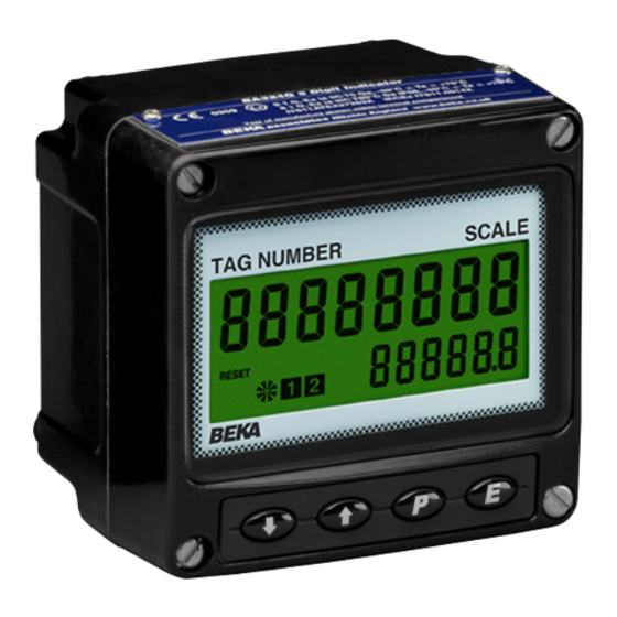
2.1 Initialisation 2.3 Displays Each time power is applied to a Tachometer The BA314G has two digital displays and associated initialisation is performed. After a short delay the annunciators, plus a pulse input indicator as shown following display sequence occurs: on page 1. -
Page 7: Intrinsic Safety Certification
3. INTRINSIC SAFETY CERTIFICATION CAUTION installation in Zone 0 The BA314G has ATEX and IECEx gas and dust certification. This section of the instruction manual When installed in a Zone 0 potentially explosive atmosphere requiring EPL Ga apparatus, the describes ATEX gas certification. ATEX dust and instrument shall be installed such that even in IECEx approvals are described in Appendixes... -
Page 8: Pulse Input Terminals
3.4 Pulse input terminals The BA314G Tachometer has a single pair of pulse 4µH input terminals 5 and 6 that may be configured for use To determine the maximum permissible cable with different types of sensor. parameters these figures should be subtracted from For sensors that require energising to determine their the maximum permitted output parameters Lo and state, such as switch contacts or a 2-wire proximity... -
Page 9: Remote Reset Terminals
The Tachometer certification information label is fitted in a recess on the top outer surface of the instrument enclosure. It shows the ATEX, IECEx and ETL certification information plus BEKA associates name, location, year of manufacture and the instrument serial number. Other certification information may also be included. -
Page 10: Power Supply
Alternatively the pulse source may be located in the Although this allows a wide variety of barriers to be safe area. Fig 3 shows how an additional Zener used, a positive polarity 28V; 93mA; 300Ω Zener barrier is used to transfer the signal to the Tachometer barrier, which has an end-to-end resistance of about in the hazardous area. -
Page 11: Switch Contact Input
4.1.3 Switch contact input 4.1.6 Magnetic pick-off input Any mechanically or magnetically activated switch Sensors incorporating a magnetic pick-off to sense contact located in the same hazardous area as the movement will have a low level voltage output Tachometer may be directly connected to pulse input unless the sensor incorporates an amplifier. -
Page 12: Remote Reset
4.1.8 Remote reset 4.2 Use with Galvanic Isolators The Tachometer's run-time display may be remotely Galvanic isolators probably simplest reset to zero by connecting terminals RS1 and RS2 intrinsically safe interface to install as they provide together for more than one second. Permanent isolation and do not require a high integrity earth interconnection inhibits the run-time clock. -
Page 13: Power Supply
The BA314G Tachometer may be used with sensors having a wide variety of pulse outputs. The following table shows the switching thresholds for each type. For reliable operation the Tachometers input signal must fall below the lower threshold and rise above the upper threshold. -
Page 14: 2-Wire Proximity Detector Input
4.2.5 2-wire proximity detector input 4.2.7 Voltage pulse input Most certified intrinsically safe NAMUR 2-wire Two voltage pulse input ranges are independently proximity detectors may be directly connected to a selectable in the BA314G Tachometer configuration BA314G input, providing the input safety parameters menu, VoLt5 L and VoLt5 H. -
Page 15: Installation
INSTALLATION Location The BA314G Tachometer is housed in robust IP66 glass reinforced polyester (GRP) enclosure incorporating an armoured glass window and stainless steel fittings making it suitable for exterior mounting in most industrial on-shore and off-shore installations. The Tachometer should be positioned where the display is not in continuous direct sunlight. -
Page 16: Emc
Custom printed scale cards are available from BEKA associates as an accessory. To remove the scale card from a Tachometer carefully pull the transparent tab at the rear of the instrument assembly away from the assembly as shown in Fig 8a. -
Page 17: Configuration And Calibration
6.0 CONFIGURATION & CALIBRATION The BA314G Tachometer is configured and calibrated via four front panel push buttons. All the configuration functions are contained in an easy to use intuitive menu that is shown diagrammatically in Fig 10. Each menu function is summarised in section 6.3 of this manual and each summary includes a reference to more detailed information. - Page 18 6.3 Summary of configuration functions Display Summary of function This section summarises configuration functions. When read in conjunction with Fig 10 it Decimal points provides a quick aid for configuring the Tachometer. If Defines the position of the decimal more detail is required, each section contains a point in the Tachometer speed reference to a full description of the function.
- Page 19 Display Summary of function Display Summary of function Local reset Resets grand total run-time to LoC clr CLr Gtot Contains sub-menu with zero. functions enabling run-time This function resets the grand total display and grand total run-time to be run-time to zero from within the reset to zero via the front panel push configuration menu when CLr YE5 is buttons when the Tachometer is in the...
- Page 22 6.4 Input: inPut 6.6 Debounce: dEbouncE Input function contains sub-functions dEbouncE is an adjustable sub-menu in the inPut which configure function which prevents the Tachometer miscounting inP . tYPE dEbounCE Tachometer input and define the amount of input when the input pulse has noisy edges, such as those noise rejection.
-
Page 23: Position Of The Decimal Points: Dp
6.7 Display update interval: uPdAtE If the Tachometer display is likely to change rapidly, a When this digit has been adjusted as required, longer interval between display updates may simplify pressing ( will transfer control to the next digit. reading the display. This function allows one of six When all the digits have been adjusted pressing different display intervals between 0.5 and 5 seconds ( will transfer control to the decimal point which... -
Page 24: Clip-Off: Clp Off
The second digit defines the deviation from the To check or change the clip-off threshold select displayed speed at which the filtering defined by the CLP oFF from the configuration menu and press first digit will be overridden and the Tachometer speed ( which will reveal the current setting. -
Page 25: Local Grand Total Run-Time Reset: Clr Gtot
Using the & or * button select mode. clr gtot and press ( which will show if the local Please contact BEKA associates sales department if grand total reset is on or oFF. If set as required the security code is lost. -
Page 26: Pulse Output
6.20 Pulse output All BA314G Tachometers have an isolated open collector pulse output having following parameters: 60 + 3V Roff Imax 10mA The output pulse may be a synchronous duplicate of the input pulse or may be scaled and the pulse length extended. -
Page 27: Enable Pulse Output
6.20.6 Source of output pulse: 5ourCE The output pulse may be derived from: Synchronously re-transmitted dirECt input pulse. Output pulse is a duplicate of the Tachometer input pulse. Input pulse scaled prior to re- 5CALEd transmission. Input pulse frequency may be divided to produce output pulse with defined duration by the diVidE and durAtion functions. -
Page 28: Define Output Pulse Width
6.20.8 Define output pulse width: durAtion When 5CALEd is selected in the 5ourCE function as described in section 6.20.6, the output pulse width in milliseconds is defined by this function. One of 11 pulse widths may be selected: 0 . 1 0 . -
Page 29: Configuration Example
7. CONFIGURATION EXAMPLE In this example a BA314G Tachometer is connected to Using the & or * push button select a proximity detector producing 105 pulses per 0 . 5 (0.5 seconds i.e. 2 display updates revolution. per second). Enter the selection and return to the uPdAtE prompt in the The BA314G is required to display rotational speed in configuration menu by pressing the ) - Page 30 Step 7 Enter the speed timebase Step 9 Define clip-off The speed timebase determines if the In this example the run-time clock is Tachometer displays speed per second, required to operate when the display per minute or per hour. In this example speed equals or exceeds 5 RPM.
- Page 31 Step 14 Reset the grand total to zero Step 16 Return to the display mode Before completing configuration the run- Configuration of the BA314G is now time grand total should be reset to zero. complete. Pressing the ) button will Using the &...
-
Page 32: Maintenance
Increase debounce 8.3 Servicing and/or display filter. We recommend that faulty BA314G Tachometers See 6.12 are returned to BEKA associates or to your local Unable to enter Incorrect security That the correct configuration code. security code is BEKA agent for repair. -
Page 33: Units Of Measurement And Instrument Identification
9. ACCESSORIES 9.3 Alarms Units of measurement & instrument The BA314G Tachometer can be supplied with identification. factory fitted, dual isolated solid state single pole New BA314G Tachometers are supplied with a printed alarm outputs that may be independently configured. scale card showing the units of measurement and tag Each may be configured as a speed or run-time information specified when the instrument was... -
Page 34: Intrinsic Safety
To determine the maximum permissible cable parameters Ci should be subtracted from the maximum permitted external capacitance specified by the certificate for the intrinsically safe interface powering the alarm circuit, such as the solenoid driver and switch transfer galvanic isolators shown in Fig 14. - Page 35 9.3.3 Configuration and adjustment Display Summary of function When a BA314G is supplied with alarms the configuration menu is extended as shown in Fig 15 Normally open or normally closed no . nc which for simplicity only shows alarm AL1 configured output.
-
Page 37: Alarm Enable: Enbl
9.3.4 Alarm enable: EnbL 9.3.8 Alarm output status: no . nC This function allows the alarm to be enabled or Each single pole alarm output may be open or disabled without altering any of the alarm parameters. closed in the non-alarm condition. When the BA314G or BA318E power supply is turned off or Using the &... -
Page 38: Alarm Silence Time: 5Il
& or * push button to adjust the flashing digit and Please contact BEKA associates sales department if the ( button to transfer control to the next digit. the security code is lost. - Page 39 Fig 16 Setpoint adjustment from the display mode To adjust an alarm setpoint select 5P1x or 5P2x and press ( which will reveal the current setting. The flashing digit of the setpoint may be adjusted using the & or * push button and the ( button to transfer control to the next digit.
-
Page 40: 4/20Ma Output
9.4 4/20mA output The BA314G Tachometer can be supplied with a factory fitted galvanically isolated 4/20mA output which may be configured to represent any part of the Tachometer speed display. 9.4.1 Intrinsic safety The 4/20mA output has been certified as a separate galvanically isolated intrinsically safe circuit complying with the requirements for simple apparatus. -
Page 41: Access 4/20Ma Output Sub-Menu
9.4.4 Access 4/20mA output sub-menu: 4-20 oP Access the Tachometer configuration menu as described in section 6.2. Using the & and * push buttons scroll though the menu until 4-20 oP is displayed, pressing ( will then access the 4/20mA output sub-menu which is shown in Fig 18. - Page 42 APPENDIX 1 A1.2 Installation and maintenance The installation requirement described in this manual ATEX Dust Certification for use in a gas potentially explosive atmospheres also apply when the Tachometer is installed in a dust potentially explosive atmosphere. A1.0 ATEX dust certification In addition to ATEX certification permitting installation The instrument assembly should only be removed in explosive gas atmospheres which is described in...
- Page 43 For additional information about the IECEx certification scheme and to view the BEKA associate certificates, please visit www.iecex.com A2.1 IECEx Certificate of Conformity BA314G Tachometer optional accessories have been issued with an IECEx Certificate of Conformity number IECEx ITS 16.0004X...
- Page 44 Zener barriers or galvanic isolators. A3.0 cETL Mark For installations in the USA and Canada, the BA314G Installations must comply with BEKA associates Tachometer has ETL and cETL intrinsic safety and Control Drawing CI330-53, which is attached to this nonincendive approval, Control Number 4008610.
- Page 57 Do not remove the original and installation procedure. escutcheon. The BA314E can also be supplied with a blank or A4.2 Certification custom laser engraved stainless steel plate secured The BA314E has the same ATEX, IECEx and ETL...
- Page 58 Fig A4.2. Replace the instrument terminal cover and evenly tighten the two 'A' screws. If the BA314E is not bolted to an earthed post or structure, the earth terminal should be connected to the plant potential equalising conductor.
Need help?
Do you have a question about the BA314E and is the answer not in the manual?
Questions and answers