Table of Contents
Advertisement
Available languages
Available languages
Quick Links
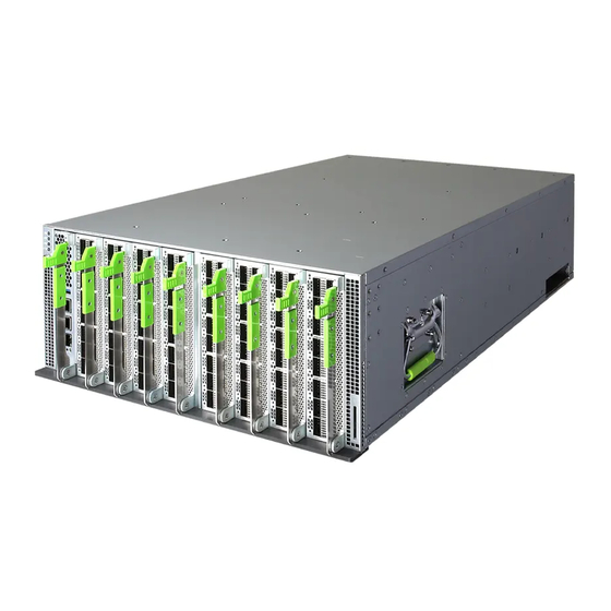
Quick Start Guide
128-Port 100G Chassis Switch
Minipack-AS8000
Warning:
For a safe and reliable installation, use only
the accessories and screws provided with the Minipack-
AS8000. Use of other accessories and screws could result
in damage to the unit. Any damages incurred by using
unapproved accessories are not covered by the warranty.
Avertissement:
Pour une installation sûre et fiable,
utilisez uniquement les accessoires et les vis fournies avec
le Minipack-AS8000. L'utilisation d'autres accessoires et
vis pourrait endommager l'appareil. Les dommages
causés par l'utilisation d'accessoires non approuvés ne
sont pas couverts par la garantie.
Warning:
The top of the enclosure is a hot surface. Do not
touch!
Avertissement:
La surface du dessus du boîtier est
brûlante. Ne pas la toucher!
Caution:
Install in a restricted access location.
Attention:
Installer dans un endroit d'accès restreint.
1
Install Rack-Rails in a 19-inch Rack
The chassis requires L-shaped rack-rails (ordered separately) to first
be installed in an 19-inch rack. Use the rack alignment templates to
install rack-rails at the correct locations in the rack allowing for the
height of the chassis (4RU). Three templates per rack post are
required for the full rack height. It is recommended to use a total of
12 templates, three on each rack post. Note that the magnetic
templates can be reused.
Bottom
1
1.
Align the cable-management T-pin on the rails with the Minipack
numbers on the templates. The Minipack numbers are color
coded for each template position on a rack post; green
(bottom), orange (middle), and blue (top).
www.edge-core.com
Package Contents
2
3
1
Middle
Top
1.
2.
3.
4.
4
5
5.
a. Using Screw-Type Rack-Rails
Front Post
1
1.
Use two #12-24-16L rack screws to secure each rack-rail to the
front post of the rack.
2.
Adjust the length of the rack-rails to reach the rear post of the
rack and secure them with two #12-24-16L rack screws on each
side.
b. Using Tool-Less Rack-Rails
Front Post
1.
Push the latch button to lock each rack-rail to the front post of
the rack. (Optionally use rack screws for added security.)
2.
Adjust the length of the rack-rails to reach the rear post of the
rack and push the latch button to lock them to the post.
(Optionally use #12-24-16L rack screws for added security.)
c. Using Adapters for 29-inch-Deep Racks
1.
Use two #12-24-16L rack screws to secure each adapter to the
rear post of the rack.
2.
Attach the rack rails to the rack adapters.
– 1 –
Minipack-AS8000
AC power cord retention clip (x4)
Power cord (x4)
Console Cable—RJ-45 to DB-9
Documentation—Quick Start Guide (this
document)
Rear Post
Rear Post
1
2
2
1
2
E082019-CS-R02
150200002142A
Advertisement
Table of Contents

Related Manuals for Edge-Core Minipack-AS8000


Summary of Contents for Edge-Core Minipack-AS8000
- Page 1 Avertissement: Pour une installation sûre et fiable, utilisez uniquement les accessoires et les vis fournies avec le Minipack-AS8000. L’utilisation d’autres accessoires et vis pourrait endommager l’appareil. Les dommages causés par l’utilisation d’accessoires non approuvés ne sont pas couverts par la garantie.
-
Page 2: Connect Power
Quick Start Guide Mount the Chassis in the Rack Use the power cord retention clips to secure the power cord connections to the PSUs. Use the four lifting handles to place the chassis onto the installed L-shaped rack-rails in the rack. Verify System Power Slide the chassis fully into the rack until its front brackets are flush with the front rack posts. -
Page 3: Replacing Fan Trays
Quick Start Guide 25G mode, or four-lane 10G mode. The following cable types Caution: If an SCM or PIM module does not power on or are supported: its release lever not correctly latch into its closed position, remove the module and install again. ■... -
Page 4: Hardware Specifications
Quick Start Guide Hardware Specifications Switch Chassis Size (WxDxH) 440.4 x 755.5 x 176.2 mm (17.34 x 29.74 x 6.94 in.), Weight 55 kg (121.25 lb), with 1 SCM, 8 PIMs, 8 fan trays, and 4 PSUs Temperature Operating: 0° C to 45° C (32° F to 113° F) Storage: -40°... - Page 5 快 速 入 門 指 南 128 埠 100G 機殼交換器 Minipack-AS8000 包裝內容物 Minipack-AS8000 交流電源線固定夾 (x4) 電源線 (x4) 控制電纜- RJ45 轉 DB-9 快速入門指南 文件- (本文件) 調整機架滑軌的長度以觸及機架的後柱,並用兩個# 12-24- 警告: 為了可以更安全的使用與安裝機台,請務必使用 16L 機架螺絲在兩邊固定它們。 隨貨附贈的配件,避免導致設備損壞 Minipack-AS80000 或其他風險產生。 使用未經批准的配件造成的任何損壞, b. 使用免工具機架滑軌 均不在保修範圍內。 前柱 後柱 警告:...
- Page 6 快速入門指南 將機箱完全滑入機架,直至其前支架與前機架支柱齊平。 確認系統電源 使用四個# 12-24-16L 螺絲,將交換器固定在機架中。 安裝機架導風板 透過檢查機箱上的 LED 來驗證系統電源。 運作正常時,LED 應全部亮藍燈。 在機架中的機箱單位之間安裝機架導風板。 使用兩個 M4 螺絲 (附帶於導風板)將導風板固定於機架滑 連接網路線 軌的前端。 連接電源 將 100 歐姆 5e 等級 (或以上)雙絞線,連接到系統控制器模 組 (SCM)上的 1000BASE-T RJ-45 管理埠。 將網路線連接到 QSFP28 介面: 若要連接光纖電纜,請先安裝 QSFP28 光纖收發器,然後 ■ 在機箱中最多安裝四個通用交流電源供應器 (PSU) 。 (機箱 將光纖纜線連接至收發器連接埠。...
- Page 7 快速入門指南 移除 / 安裝 SCM 和 PIM 模組 更換風扇托盤 交換器系統出廠時,已安裝了八個風扇托盤。若檢測到風扇故 障,應盡速更換有問題的風扇托盤。 說明: 風扇托盤是可熱插拔的,無需關閉交換器即可進 行更換。 移除模組 注意: 從機箱中移除埠介面模組 (PIM)之前,請中斷 所有網路連接。 使用 ESD 靜電消除腕帶,並將其連接到機箱上的 ESD 點。 注意: 每一風扇托盤插槽都須安裝風扇托盤。風扇托盤 故障時應盡速更換。 抓住釋放桿把手,並向下拉以釋放模組上的桿鎖。 向下拉釋放桿,使模組從機箱背板鬆開。 按下風扇托盤把手上的釋放按鈕。 將模組滑出機箱。 用力拉動風扇托盤把手,直至風扇托盤鬆開,再將其滑出交 換器。 安裝模組 將替換風扇托盤插入插槽,然後將其緩慢滑入機箱,直至其 就定位。LED 應該打開,且風扇立即開始運轉。 更換 PSU (電源供應器) 交換器系統在機箱中最多可支援四個...
- Page 8 快速入門指南 硬體規格 交換器機箱 尺寸(寬 x 深 440.4 x 755.5 x 176.2 mm (17.34 x 29.74 x 6.94 吋 ),4RU x 高) 重量 55 公斤 (121.25 磅) ,附 1 個 SCM,8 個 PIM,8 個風扇托盤和 4 個 PSU 溫度 操作:0° C 至 45° C (32° F 至 113° F) 儲存:-40°...
-
Page 9: Warnings And Cautionary Messages
Quick Start Guide Warnings and Cautionary Messages 注意: 請配戴防靜電腕帶或採取其他適當措施,避免處 理設備時的靜電放電。 Warning: Installation and removal of the unit must be 注意: 請勿將電話插孔接頭插入 RJ-45 連接埠。這可能 performed by qualified personnel only. 損壞此裝置。 Warning: When connecting this device to a power outlet, 注意: 僅限使用具備 RJ-45 接頭且符合 FCC 標準的雙 connect the field ground lead on the tri-pole power plug to 絞線電纜。... - Page 10 Quick Start Guide 電源供應器如果發生損壞,切勿自行修理,請交由授權經銷商處 ■ Japan - VCCI Class A 理。 產品的機殼、鐵片大部份都經過防割傷處理,但是您仍必須注意 ■ 避免被某些細部鐵片尖端及邊緣割傷,拆裝機殼時最好能夠戴上 手套。 當你有一陣子不使用產品時,休假或是颱風天,請關閉電源之後 ■ BSMI (Taiwan) 將電源線拔掉。 警告使用者 : Laser Safety 此為甲類資訊技術設備,於居住環境中使用時,可能會造成 射頻擾動,在此種情況下,使用者會被要求採取某些適當的 Warning: Fiber Optic Port Safety: 對策。 When using a fiber optic port, never look at the transmit CLASS 1 laser while it is powered on.
- Page 11 Quick Start Guide Cordon électrique - Il doit être agréé dans le pays d’utilisation Power Cord Set Etats-Unis et Le cordon doit avoir reçu l’homologation des UL et un U.S.A. and The cord set must be UL-approved and CSA certified. Canada: certificat de la CSA.
- Page 12 Quick Start Guide Power and Battery Safety Warning: If your switch uses a lithium battery, do not attempt to replace the battery yourself. Return the switch to the manufacturer for battery replacement. Avertissement: Si votre commutateur utilise une batterie au lithium, n’essayez pas de la remplacer vous-même.
Need help?
Do you have a question about the Minipack-AS8000 and is the answer not in the manual?
Questions and answers