
Related Manuals for Lennox MS8


Summary of Contents for Lennox MS8
- Page 1 E 2012 Lennox Industries Inc. Dallas, Texas, USA 507022-01 10/2012 Single-Zone Mini-Split System Air Conditioners and Heat Pumps This manual is the property of the homeowner and must be left with the user.
- Page 2 Warnings WARNING ELECTRICAL SHOCK, FIRE, OR EXPLOSION HAZARD. Failure to follow safety warnings exactly could result in dangerous op eration, serious injury, death or property damage. Improper installation, adjustment, alteration, service or maintenance can cause property damage, personal injury or loss of life. Installation and service must be performed by a licensed professional installer (or equivalent), or a service agency.
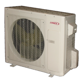
- Page 3 Parts Arrangement Indoor unit (Typical indoor unit shown. Actual unit may be slightly different.) Air inlet Front Panel Display Filter Wrapping Tape Wall Pipe Directional Louver Air outlet Wireless remote control Indoor Unit Display Receiver Cooling Power/Run Heating Temperature Dehumidification Setting (or error code) Outdoor unit...
- Page 4 Important Operating Instructions IMPORTANT To ensure comfort, make sure that temperature selection has been properly set at the remote control. To ensure efficient operation, do not block air intake or outlet at either the indoor or outdoor unit. Do not stand on outdoor unit or store items on top of unit. Make sure that indoor unit directional louver is properly adjusted.
- Page 5 Make sure adjustable during DEHUMIDIFI These buttons are not that there are no obstructions CATION mode operation. The functional in the MS8 between the indoor unit re low fan speed is necessary system. ceiver and the remote control.
- Page 6 Wireless Remote Functions (Continued) SWITCH FROM °C TO °F With system OFF, press MODE TIMER ON button and - buttons simultaneously to Use the TIMER ON button to ini switch from Centigrade to tiate or cancel a single timed-on Fahrenheit. Current selection event.
- Page 7 Wireless Remote Functions (Continued) LOUVER SETTING button Press the TEMP button again to display the outdoor ambient tem Use the LOUVER SETTING but perature icon. The outdoor ton to choose a preferred louver ambient temperature display is setting, rather than the default not available on this system.
- Page 8 System Start Up Using Wireless Remote General Operation 1 - Press POWER button once to turn system on. 2 - Press MODE button until desired operating mode icon is displayed. NOTE - When AUTO mode is selected, the temperature setting is not displayed on the remote control.
- Page 9 Remote Control — Important Information The wireless remote control requires two AAA, 1.5V batteries. DO NOT attempt to use any other type of battery. Follow the steps below and in the illustrations to replace the batteries when necessary. 1 - Remove screw that secures the battery access panel to the remote.
- Page 10 Do not use soap or other cleaners and DO NOT spray water into unit. WARNING! SHOCK HAZARD! DO NOT SPRAY water into outdoor unit. Failure to follow this warning could lead to electrical shock, resulting in personal injury or death. Lennox recommends annual inspection by a licensed professional service technician, or equiva lent.
- Page 11 Troubleshooting WARNING! ELECTRICAL SHOCK HAZARD! Never attempt to repair the indoor or outdoor unit yourself. System repairs must be performed by a licensed, professional technician, or equivalent. If any of the following conditions exist, immediately turn the system (indoor and outdoor units) off at the unit disconnect switch and call a licensed professional technician, or equivalent, for repairs There is a very loud sound during unit operation.
- Page 12 Auto ON Switch If the remote control is lost or damaged, or if AUTO Switch charged AAA, 1.5V batteries are not avail (Recessed) able, the Auto ON switch can be used to turn AUTO the system on or off. The Auto ON switch is located behind the cover panel on the indoor unit.
Need help?
Do you have a question about the MS8 and is the answer not in the manual?
Questions and answers
I have a Lennox MS There are no lights on the panel but the unit is on. What do i do??
If there are no lights on the panel of a Lennox MS8 unit but the unit is on, it may indicate that the system is operating within normal parameters. The outdoor unit LED status showing "NONE" for all indicators (D5, D6, D16, D30) means no errors are present and the system is functioning correctly.
This answer is automatically generated