Table of Contents
Advertisement
2021 Lennox Industries Inc.
©
Dallas, Texas, USA
General .....................................................................................1
Included Parts...........................................................................2
Indoor / Outdoor Unit Match-Ups..............................................2
Model Number Identification .....................................................3
Typical Single-Zone System Components................................4
System Dimensions ..................................................................5
Outdoor Units ................................................................................................... 5
Indoor Units ...................................................................................................... 8
System Clearances ..................................................................8
Outdoor Unit ..................................................................................................... 8
Indoor Unit ........................................................................................................ 9
Torque Requirements for Caps and Fasteners.........................9
Indoor Unit Installation ............................................................10
Unit Placement Considerations ...................................................................... 10
Floor Installation ............................................................................................. 10
Ceiling Installation .......................................................................................... 11
Indoor Unit Condensate Piping Connections ................................................. 11
Outdoor Unit Installation .........................................................12
Placement Considerations ............................................................................. 12
Direct Sunlight, Rain, Snow and Ice Protection .............................................. 12
Prevailing Winds ............................................................................................. 13
Buried Refrigerant Pipe Protection ................................................................. 14
Outdoor Unit Condensate Piping .................................................................... 14
Securing the Outdoor Unit .............................................................................. 14
Refrigerant Piping Connections ..............................................15
Leak Test and Evacuation ......................................................17
Leak Test ........................................................................................................ 17
Triple Evacuation Procedure .......................................................................... 17
Wiring Connections ................................................................17
Outdoor Unit .................................................................................................. 17
Indoor Unit ...................................................................................................... 17
Installation Wiring Requirements .................................................................... 19
Control Board Wiring Connections ................................................................. 20
Unit Start-Up ...........................................................................26
Adding Refrigerant for Longer Line Set ..................................26
Troubleshooting ......................................................................27
Indoor Unit Error Codes ................................................................................. 27
Outdoor Unit Error Codes ............................................................................... 27
Self Clean Feature..................................................................27
Test Run .................................................................................27
Pre-Checks ..................................................................................................... 27
Procedure ....................................................................................................... 27
Dry Mode Operation (Dehumidification) .................................27
Procedure ....................................................................................................... 27
Sequence of Operation .................................................................................. 27
INSTALLATION
INSTRUCTIONS
MLB/MPC Outdoor Units
with MCFA/MCFB Indoor
SINGLE-ZONE MINI-SPLIT SYSTEMS
(208/230V) --
Ceiling / Floor Indoor Units
507548-08 10/2021
Supersedes 507548-07
THIS MANUAL MUST BE LEFT WITH THE OWNER
FOR FUTURE REFERENCE
WARNING
Improper installation, adjustment, alteration, ser vice or
maintenance can cause property damage, personal
injury or loss of life.
Installation and service must be performed by a li censed
professional HVAC installer (or equivalent) or a service
agency.
WARNING
The clean Air Act of 1990 bans the intentional venting of
refrigerant (CFCs, HCFCs, and HFCs) as of July, 1992.
Approved methods of recovery, recycling or reclaiming
must be followed. Fines and/or incarceration may be
levied for non-compliance.
CAUTION
As with any mechanical equipment, contact with sharp
sheet metal edges can result in personal injury. Take
care while handling this equipment and wear gloves and
protective clothing.
General
Refer to the Product Specifications bulletin (EHB) for more
product information.
These instructions are intended as a general guide and
do not supersede local or national codes in any way.
Authorities having jurisdiction should be consulted before
installation.
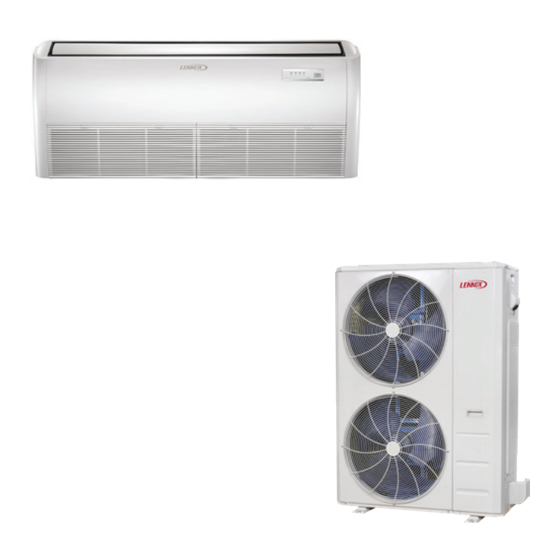
The MCFA and MCFB Ceiling/Floor indoor units are
matched with an outdoor heat pump unit to create a mini-
split system that uses HFC-410A refrigerant.
Units
Advertisement
Table of Contents

Related Manuals for Lennox MLB Series


Summary of Contents for Lennox MLB Series
-
Page 1: Table Of Contents
INSTALLATION INSTRUCTIONS 2021 Lennox Industries Inc. © MLB/MPC Outdoor Units Dallas, Texas, USA with MCFA/MCFB Indoor Units SINGLE-ZONE MINI-SPLIT SYSTEMS (208/230V) -- Ceiling / Floor Indoor Units 507548-08 10/2021 Supersedes 507548-07 THIS MANUAL MUST BE LEFT WITH THE OWNER FOR FUTURE REFERENCE... -
Page 2: Included Parts
Included Parts Package 1 of 1 contains the following: 1 - Assembled Indoor Unit Parts Figure Quantity Parts Figure Quantity M0STAT60Q-1 Installation and owner’s 1 ea. Wireless controller manual Wireless control holder with 2 mounting Batteries (AAA) screws 3/4” Drain Adapter Conduit Installation Plate with two band claps. -
Page 3: Model Number Identification
Model Number Identification OUTDOOR SINGLE ZONE HEAT PUMP UNITS M P C 009 S 4 S - 1 P Series Type Voltage M = Mini-Split P = 208/230V-1 phase-60hz Unit Type L = Low Ambient Heat Pump Minor Design Sequence P = Heat Pump 1 = 1st Revision Refrigerant Circuits... -
Page 4: Typical Single-Zone System Components
Typical Single-Zone System Components MPORTANT - Condensate drain line must always be located at the bottom of the Line set bundle.) (wrapped in foam insulation) Wiring Communication cable Suppl y Air 036 and 048 only Indoor unit wiring connections Tape Condensate drain line (wrapped in foam insulation) Refrigerant Line Set, Condensate Line... -
Page 5: System Dimensions
System Dimensions Outdoor Units 1/2 (13) 13-3/4 12-3/4 (349) (324) (381) 2-7/8 (73) 2-7/8 (73) TOP VIEW 35-1/4 (895) 26-1/2 GAS VALVE (673) LIQUID VALVE 2-3/8 (60) 4-1/4 (108) 26-1/8 (664) 13-1/2 (343) 35 (889) SIDE VIEW 37-5/8 955) FRONT VIEW Figure 2. - Page 6 27-7/8 (708) 25 (635) 17-5/8 15-7/8 (448) (403) TOP VIEW (76) 16-3/8 (416) 52-1/2 (1333) 37-1/2 (953) 41-1/8 (1045) SIDE VIEW FRONT VIEW Figure 4. MPC036S4S and MPC048S4S Outdoor Unit Dimensions - Inches (mm) 1/2 (13) 13-3/4 12-3/4 (349) (324) (381) 2-7/8 (73) 2-7/8 (73)
- Page 7 DRAIN HOLE (Bottom of Unit) 18-1/8 (460) 3-5/8 (92) 15-7/8 (403) 15-1/4 (387) (457) 1 (25) 2-7/8 (73) TOP VIEW 40-1/2 (1029) 31-7/8 (810) GAS VALVE LIQUID VALVE 2-3/8 (60) 4-1/4 (108) 26-1/2 (673) 16-1/8 (410) SIDE VIEW 37-1/4 (946) FRONT VIEW Figure 6.
-
Page 8: Indoor Units
Indoor Units 26-5/8 8-3/4 (676) (222) 9-1/4 (235) FRONT VIEW SIDE VIEW BACK VIEW 4-3/4 (120) BOTTOM VIEW (152) (203) 9-1/2 (241) Model No. MCFA024S4S-*P 42-1/8 1070 MCFA036S4S-*P 50-5/8 1286 47-3/8 1203 MCFA048S4S-*P 1651 61-3/4 1568 MCFB018S4S-*P 42-1/8 1070 Figure 8. MCFA and MCFB Indoor Unit Dimensions - Inches (mm) System Clearances Outdoor Unit 24 (610) -
Page 9: Indoor Unit
Using an Allen wrench rated at less than 50Rc risks rounding or breaking off the wrench, or stripping the valve stem recess. See the Lennox Service and Application Notes C-08-1 for further details and information. -
Page 10: Indoor Unit Installation
Indoor Unit Installation Electrical CAUTION Connections In order to avoid injury, take proper precaution when lifting heavy objects. Refrigerant / Drain Pipe Connections Unit Placement Considerations Figure 11. Floor / Wall Applications AVOID Units are wall mounted using factory-installed hanging Do not install the unit in the following locations: brackets. -
Page 11: Ceiling Installation
6. If necessary, install a field-provided isolation grommet Ceiling Installation to prevent transmission of vibration from unit to structural ceiling. • Locate a suitable position within the space where maintenance access and supply air will not be restrict- ed or affected by obstacles Threaded Rod •... -
Page 12: Outdoor Unit Installation
4. After the system installation is complete, the Building Structure condensate drain line must be checked for leaks and proper drainage. If a field-provided condensate pump has been installed, it must be checked to ensure proper operation. This check is part of the start-up process which must be done by the installing contractor. -
Page 13: Prevailing Winds
• The unit base should be elevated above the depth of average snows as illustrated in “Figure 20. Outdoor Unit on Brackets above Snow Line” • In heavy snow areas, do not place the unit where drift- ing will occur as illustrated in “Figure 21. Outdoor Unit Air Flow Obstructed by Snow”... -
Page 14: Buried Refrigerant Pipe Protection
24 in 610 mm 24 in 12 in 610 mm 305 mm 12 in 305 mm Condensate Drain Drain (location varies per model) Chassis Connector NOTE - Minimum clearances shown. Figure 26. Condensate Drain Figure 24. Dog House-Style Shelter Securing the Outdoor Unit Slab or Roof Mounting Install the unit a minimum of 4 inches (102 mm) above the roof or ground surface to avoid ice build-up around the... -
Page 15: Refrigerant Piping Connections
Securing Outdoor Unit To Hanging Brackets Table 2. Flaring Piping If the outdoor unit is installed on field-provided wall Flare Dimension mounting brackets, use lag bolts or equivalent to secure A (mm) Pipe Diameter Flare Shape the outdoor unit to the bracket. Minimum rear clearance can be reduced to 6 inches (152 mm) when mounted 1/4”... - Page 16 should always be accessible and must be insulated Table 3. Refrigerant Piping and Indoor Unit to prevent condensation. Connection Sizes 17. After refrigerant piping has been installed and checked Size Liquid Line Gas Line for leaks, apply insulation over all flared connections. (Btuh) 24000, 36000 &...
-
Page 17: Leak Test And Evacuation
3. Evacuate the system to a reading of 5000 Microns (5 Leak Test and Evacuation Torr). 4. Break the vacuum by allowing nitrogen into the port Air and moisture remaining in the refrigerant system will connections (liquid and gas line pipes) until a positive have undesirable effects as indicated below: pressure is achieved •... - Page 18 IMPORTANT Install unit so that unit disconnect is accessible. Use specified wiring and cable to make electrical This unit must be properly grounded and protected by a connections. Clamp cables securely and make sure that circuit breaker. The ground wire for the unit must not be connections are tight to avoid strain on wiring.
-
Page 19: Installation Wiring Requirements
Installation Wiring Requirements Table 7. Single Zone Installation Wiring Requirements System and Terminal Number of System Capacity System Voltage Wire Type Wire Gauge / MCA Designations Conductors Indoor to Outdoor Wiring Stranded and (Communication/ 208/230VAC 16AWG unshielded Power) 1, 2, 3 and GND Outdoor to Main Power Stranded and 208/230VAC... -
Page 20: Control Board Wiring Connections
Control Board Wiring Connections • • • • • COMPONENT IN DASH Inductor INDOOR UNIT MAINBOARD LINE IS OPTIONAL Ceiling-Floor Type OR FIELD WIRING. CN18 CN1 5 DC MOTOR F O R S E T T IN G AU T O -R E S TAR T F O R S E T T IN G AU T O -R E S TAR T DRIVER MODULE CN21... - Page 21 INDOOR UNIT MAINBOARD In d u c to r Ceiling-Floor Type CN18 CN1 3 CN21 DC MOTOR DRIVER MODULE FAN1 CN24 SWING VSWING(INACTIVE) TO PROGRAMMA BLE CN40 WIRED CONTROLLER DISPLA Y TO WI RED CN10A BOARD CONTRO LLER BLACK INDO OR C OIL T EMP. SENS OR WHITE ROOM TEMP.
- Page 22 WIRING DIAGRAM INDOOR UNIT POWER SUPPLY T3 T4 BLUE CN16 CN19 CN17 CN6 CN8 CN7 CN2 CRANKCASE EARTH L-IN N-IN 4- WAY T.M.P_Sensor HEATER HEATER MAIN BOARD CN18 DC FAN CN2 7/8 INPUT 230V CN18 OUTPUT 0~12V DC CN414 OUTPUT 0~310V AC CN60 OUTPUT 230V CN17...
- Page 23 Figure 41. 208/230V MPC036S4S-*P Outdoor Unit Wiring Diagram...
- Page 24 Figure 42. 208/230V MPC048S4S-*P Outdoor Unit Wiring Diagram...
- Page 25 NOT AVAILABLE ON 24K NOT AVAILABL E ON 24K U~V~W among phases 0~250VAC Output:0-12VDC Connect to FAN Input:0-5VDC voltage among phases 0~200VAC Output:230 VAC Output:230 VAC Intput:230 VAC Output:230 VAC Output:230 VAC CODE Figure 43. 208/230V MLB024S4S-*P Outdoor Unit Wiring Diagram...
-
Page 26: Unit Start-Up
BLACK BLUE BROWN IPM&PFC BOARD Outdoor main Controller Outdoor main Controller BLACK Notes: BLUE This symbol indicates the element is optional, the actual shape shall be prevail. BLACK CODE HEAT_D PART NAME WHITE COMP COMPRESSOR COMP The electric heating belt of chassis CAP1,CAP2 FAN MOTOR CAPACITOR BLACK... -
Page 27: Troubleshooting
Troubleshooting Table 10. MLB and MPC Single-Zone Outdoor Unit Error Codes Indoor Unit Error Codes Display Malfunction and Protection Indication Table 9. Indoor Unit Troubleshooting Codes EC56 Outdoor T2B sensor error. Display Description Indoor unit EEPROM error EC57 Refrigerant pipe temperature sensor error. Communication error between indoor and outdoor units Indoor fan speed error Outdoor DC fan motor malfunction/fan speed out of... -
Page 28: Self Clean Feature
4. Let each function run for 5 minutes, and perform the Table 10. MLB and MPC Single-Zone Outdoor Unit following checks: Error Codes Table 8. Test Run Checklist Display Malfunction and Protection Indication Checks Pass Fail No electrical leakage PH90 High temperature protection of Evaporator Unit is properly grounded PH91...
Need help?
Do you have a question about the MLB Series and is the answer not in the manual?
Questions and answers