Advertisement
Quick Links
Advertisement

Subscribe to Our Youtube Channel
Related Manuals for IBM System Storage N3300


Summary of Contents for IBM System Storage N3300
- Page 1 IBM System Storage N3300 Installation and Setup Instructions...
- Page 3 Below is a copy of the N3300 system setup worksheet. If a worksheet has not yet been completed for this setup, remove this sheet and fill in the following information that is needed for the setup before unpacking the system unit. System setup worksheet Node B Node A...
- Page 4 System setup worksheet (continued) Node B Node A Setup Parameters (bottom node) (top node) Filer location Enter the root directory for HTTP files [/vol/vol0/home/http] Do you want to run DNS resolver? [Y/N] DNS domain name (You can enter up to three nameservers.) IP address for DNS first nameserver Do you want another nameserver? [Y/N] IP address for alternate nameserver...
- Page 5 N series product in a non-IBM rack. If the N series product is being installed in a non-IBM rack, the rails shipped with the N series product may or may not work with the non-IBM rack. Physical installation of the N series product in a non-IBM rack is the customer's responsibility.
- Page 6 Note: Accessory kit: The contents of the box will differ based on the model - IBM rail kit you purchased. See Step 1.1 for a - Power cable list of contents for specific models. - DB-9 to RJ-45 console adapter...
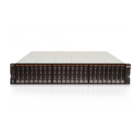
- Page 7 Verify that the shipping packages include the following items: N3300 (2859-A10) Single-controller N3300 System bezel Console adapter, RJ-45 to DB-9 Serial null modem cable ESD wrist strap Power cords Publications There will also be at least one envelope with the software EULA and license keys.
- Page 8 Installing the rails in an IBM 19-inch rack Note: Read this document in its entirety before proceeding. Note: It is recommended that the N3300 be placed in the lowest position available in a rack. For example: Model A10 Model A20...
- Page 9 Rear of rack Front of rack Rail adjustment screws Left rail Right rail Locating pins Loosen (but do not remove) the four rail adjustment screws on each rail. Use the figure on the next page for reference. At the front of the rack, position the right-hand rail into the rack at the appropriate EIA location.
- Page 10 Repeat steps 2.2 through 2.4 for the left-hand rail. FRONT REAR Section of rack EIA rail Left and Right Left and Right Rails Rails Chassis attach screws Top rail screw 1 EIA unit (1U) Locating pins Locating pins Bottom rail screw Chassis attach screws Bottom rail screw...
-
Page 11: Installing The System In The Rack
Installing the system in the rack Caution: The weight of this part or unit is between 18 and 32 kg (39.7 and 70.5 lb). It takes 2 persons to safely lift this part or 18-32 kg (39.7-70.5 lbs) unit. (C009) If the N3300 system bezel is attached to the system, carefully remove the front bezel of the N3300 by pulling out on the rectangular openings (marked by blue stripes) on either side of the bezel. - Page 12 s shown in the previous illustration, a t the front of the rack, us four black M5x40 screws (two for each rail) in the H and H holes secure the system unit to the rack. Thread the screws through the system unit bracket, the spacer plate, and the rack frame rail into the threaded rail nuts.
- Page 13 Connecting the N3300 to a network Connect the RJ-45 to DB-9 adapter from the adapter kit to the console port on the system. Connect the serial null modem cable from your console to the DB-9 end of the adapter. Connect your system to the network by plugging the network cable into the networking port, labeled e0a.
- Page 14 Connect the Remote Management port to the network (if applicable). Note: The Remote Management port gives you the capability to remotely manage your system from anywhere within a network connection. See the Data ONTAP System Administration Guide for Remote Management configuration information.
- Page 15 Connecting the N3300 to expansion units IMPORTANT: When using onboard ports to connect to EXN expansion units, onboard ports must be set to initiator mode. See "Configuring for initiator mode" in N3300 and N3600 Hardware and Service Guide for more information SFPs must be used when connecting fiber cables.
- Page 16 To cable a single-node A10, complete the following steps, using the diagram for reference. 5.3.1 Cable the N3300 port 0a to the first expansion unit module A ESH2/ESH4 or AT-FCX In port. 5.3.2 Cable the N3300 port 0b to the first expansion unit module B ESH2/ESH4 or AT-FCX In port.
- Page 17 To cable the Channel A paths in a dual-node A20 (cluster), complete the following steps, using the diagram for reference. The numbers in the diagram correspond to the step numbers below. 5.4.1 Cable the N3300 CM-A port 0a to the first expansion unit module A ESH2/ESH4 or AT-FCX In port.
- Page 18 For any additional expansion units in a loop, connect the module A Out port to the next expansion unit's module A In port. Repeat for module B. Note: Both ESH2/ESH4 and the AT-FCX modules are self- terminating. The ESH2/ESH4 does not have a terminate switch. If you have ordered the “Dual-Path FC Cabling”...
- Page 19 Note: This step is optional. You must have ordered the "Dual-Path FC Cabling" feature and/or additional fiber cables and SFP GBICs to implement this feature. Dual-path FC cabling only applies to dual-node clustered A20 models. The purpose of dual-path FC cabling is to provide each node in a dual- node cluster with redundant FC paths (Loop A and Loop B) to each stack of expansion units.
-
Page 20: Installing The Power Cables
Installing the power cables Make sure all power supply switches on the N3300 and any attached expansion units(s) are in the Off position. Connect the power cords to all power supply 1 and power supply 2 power receptacles for all system units that are being installed using power cord retainer clips as shown below. - Page 21 Grounding the N3300 Note: The N3300 has no requirement or provision for grounding. For proper grounding of expansion units, refer to the Installation and Setup Instructions for the expansion unit.
- Page 22 N3300 using the IP address specified earlier in the setup or you can continue through the command line interface. Refer to the IBM System Storage N series Data ONTAP Software Setup Guide for your version of Data ONTAP for more...
- Page 23 Check the licenses on the node(s) by entering the following command: license Add any missing licenses by entering the following command for each missing license: license add xxxx xxxx where is the license code for the product. Note: Clustering must be licensed on both nodes in a dual-node N3300. Continue with post-setup configuration as needed.
-
Page 24: Troubleshooting Tips
LOADER. Start Data ONTAP by entering autoboot at the prompt. 10. If your system does not boot successfully, it might not have the boot image downloaded on the CompactFlash card. Call IBM Service and Support at 1-800-IBM-SERV (1-800-426- 7378). -
Page 25: Additional Resources
Data ONTAP System Administration Guide The following N series publications and Web site contain additional information about N series hardware and software products. IBM System Storage N3300 and N3600 Hardware and Service Guide, GC27-2087 IBM System Storage EXN1000 Hardware and Service Guide... - Page 26 Tucson, AZ 85744-0001 Internet URL: www.ibm.com/storage/support/nas References in this publication to IBM products or services do not imply that IBM intends to make them available in every country or region. IBM, the IBM logo, and System Storage are trademarks and/or registered trademarks of International Business Machines Corporation.
Need help?
Do you have a question about the System Storage N3300 and is the answer not in the manual?
Questions and answers