
Related Manuals for Safe Fleet LMU Controller

Summary of Contents for Safe Fleet LMU Controller
- Page 1 LMU Controller Installation Guide For LMU Models 26 and 27 © Safe Fleet | March 2019 | All rights reserved | Part #: 700-1132 R3...
- Page 2 — THIS PAGE LEFT INTENTIONALLY BLANK — © Safe Fleet | March 2019 | All rights reserved | Part #: 700-1132 R3...
-
Page 3: Table Of Contents
Operation Status..................10 Set Up LMU Controller in vMax Live Plus......11 Login and Launch.. -
Page 4: Overview
The LMU Controller provides vehicle tracking to view in vMax Live Plus 5.0 for users on Sprint, Verizon, and Rogers cell networks. This guide provides instruction for installing the LMU Controller by itself or with a DVR. To work with a DVR, the DVR needs to have firmware version 2.0 or higher. -
Page 5: Installation
The Device ID is the 10 digit ESN number on the LMU Controller label. 2. Fill in the rest of the Installation Record fields for the bus installation p. 5 © Safe Fleet | March 2019 | All rights reserved | Part #: 700-1132 R3... -
Page 6: Install Lmu Controller Antenna
LMU Controller. • Use only the supplied antenna. Antennas from other manufacturers will not work with the LMU Controller. 2. Using the supplied alcohol wipe pad, clean the window surface where the antenna will be installed. 3. Peel the protective cover from the foam backing on antenna. -
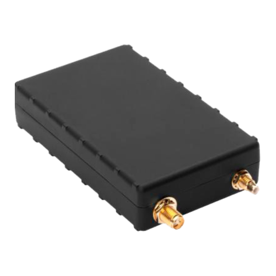
Page 7: Install Lmu Controller
2. Using the supplied alcohol wipe pad, clean the vehicle surface where the LMU Controller will be installed. 3. Peel the protective cover from the velcro backing on the LMU Controller. Be careful not to touch or allow any foreign material to come in contact with the exposed adhesive. - Page 8 7. Connect the alarm button’s red and black wires to the extension cable’s red and black wires with the supplied crimps. 8. If the LMU Controller is being connected to a DVR, connect the AUX 1 connector from the LMU Controller 20 pin harness to the supplied 060-1012 adapter cable, which connects to the GPS Extension cable, which connects to the DVR’s GPS socket.
-
Page 9: Lmu Controller Leds
Once the 20 pin harness is connected to the LMU Controller, this will have power. The LMU Controller is configured to provide vehicle tracking and live video streaming information to vMax Live Plus users. LEDs on the LMU Controller indicate operation status and display operation mode conditions as described below. -
Page 10: Set Up Lmu Controller In Vmax Live Plus
Seon is not responsible if the password is lost or forgotten. TO SET UP THE DVR AND LMU CONTROLLER 1. In vMax Live Plus, in the main view, click Integrations. p. 10 © Safe Fleet | March 2019 | All rights reserved | Part #: 700-1132 R3... - Page 11 Select the Device ID that corresponds to the LMU your are installing. Click Add. The Device ID and Integration Account will be disclosed in the table. vi. Click Save. p. 11 © Safe Fleet | March 2019 | All rights reserved | Part #: 700-1132 R3...
- Page 12 1. Click Add next to the Vehicle ID drop-down menu (see previous image). The Vehicle Details window opens. 2. Fill in the Vehicle Details: Enter a Vehicle ID. Select a Vehicle Type. iii. Select a Vehicle Group. iv. Click Save. p. 12 © Safe Fleet | March 2019 | All rights reserved | Part #: 700-1132 R3...
-
Page 13: Troubleshooting
LMU Controller Troubleshooting Troubleshooting This section provides information and procedures for troubleshooting the LMU Controller interface and the vMax Live Plus software. Troubleshooting Symptom Possible Cause Solution LMU Controller will not start The power cabling may not be Check cabling connections. -
Page 14: Specifications
100mA at 12VDC 100mA at 12VDC Power Consumption Typical 70mA at 12VDC 70mA at 12VDC POwer Consumption Sleep 3mA at 12VDC 3mA at 12VDC p. 14 © Safe Fleet | March 2019 | All rights reserved | Part #: 700-1132 R3... -
Page 15: Appendix
Please contact Technical Support if you do not have access credentials. Warranty And End-User License Agreement Complete warranty details are available at https://www.seon.com/documents/Seon-Warranty.pdf p. 15 © Safe Fleet | March 2019 | All rights reserved | Part #: 700-1132 R3...
Need help?
Do you have a question about the LMU Controller and is the answer not in the manual?
Questions and answers