Table of Contents
Advertisement
Quick Links
Document Number:
XE-MAX1PM-OPERATION-R0A
AccuMax II Fury/Fusion
--- Vehicle Mounted & Fixed Systems ---
Foam Pro Models: #3020, #3040, #3060, #3090
Level #2:–1500 to 2500 GPM: Models #3150 & #3300
OPERATION, SET-UP, CALIBRATION, SERVICE & PARTS MANUAL
MODEL MAX100
All quality FoamPro products are ruggedly designed, accurately machined, carefully assembled, thoroughly inspected and tested. In order to
maintain the high quality of your unit, and to keep it in a ready condition, it is important to follow the instructions on care and operation. Proper use
and good preventive maintenance will lengthen the life of your unit. ALWAYS INCLUDE THE UNIT SERIAL NUMBER IN CORRESPONDENCE.
FoamPro • 26 Southern Blvd. • Nesconset, NY 11767 USA • 800-533-9511 • FAX 816-892-3178
Foam Injection System
Pumper Systems
Level #1–500 to 1250 GPM
Industrial Pumpers and Fixed Systems
Level #3–3000 to 6000 GPM: Model #3300
MODEL MAX200
Unit
Serial
Number
1
MAX100/200-OPERATION Rev200813
Advertisement
Table of Contents
Troubleshooting

Subscribe to Our Youtube Channel
Related Manuals for Safe Fleet FoamPro Accumax II Fury

Summary of Contents for Safe Fleet FoamPro Accumax II Fury
- Page 1 MAX100/200-OPERATION Rev200813 Document Number: XE-MAX1PM-OPERATION-R0A AccuMax II Fury/Fusion Foam Injection System --- Vehicle Mounted & Fixed Systems --- Pumper Systems Level #1–500 to 1250 GPM Foam Pro Models: #3020, #3040, #3060, #3090 Industrial Pumpers and Fixed Systems Level #2:–1500 to 2500 GPM: Models #3150 & #3300 Level #3–3000 to 6000 GPM: Model #3300 OPERATION, SET-UP, CALIBRATION, SERVICE &...
-
Page 2: Table Of Contents
MAX100/200-OPERATION Rev200813 1. CONTENTS Table of Contents 1. CONTENTS ..........................2 2. SAFETY ............................3 Safety Precautions ........................3 3. INTRODUCTION ........................4 Overview: How the Foam System Works ..................4 4. FOAM SYSTEM DRAWINGS – BASIC ................... 6 Basic Drawings for Each System ....................6 5. -
Page 3: Safety
MAX100/200-OPERATION Rev200813 2. SAFETY Safety Precautions Throughout the AccuMax foam system installation manual, three (3) levels of precautions are denoted as follows: Cautions are used to indicate the presence of a hazard, which will or may cause minor injury or property damage if the notice is ignored. Warnings denote that a potential hazard exists and indicates procedures that must be followed exactly to either eliminate or reduce the hazard, and to avoid serious personal injury, or prevent future safety problems with the product. -
Page 4: Introduction
MAX100/200-OPERATION Rev200813 3. INTRODUCTION Overview: How the Foam System Works The FoamPro AccuMax injection system is an electronically controlled, hydraulically driven, foam concentrate proportioning system designed to provide the wide range of foam concentrate injection rates necessary for foam operations. The FoamPro AccuMax system will accurately deliver from 0.1% to 10.0% foam concentrate. - Page 5 MAX100/200-OPERATION Rev200813 The constant comparison of the water flow and foam flow information by the AccuMax system ensures the desired proportion of foam concentrate, based on water flow rate, independent of any variations in fire pump intake or discharge pressures. As water flow increases or decreases, the foam concentrate rate of injection is increased or decreased automatically to correspond to water flow, maintaining the proper concentrate percentage as selected on the FLI injector.
-
Page 6: Foam System Drawings - Basic
MAX100/200-OPERATION Rev200813 4. FOAM SYSTEM DRAWINGS – BASIC Basic Drawings for Each System Drawing #1–Fury Single-Point... - Page 7 MAX100/200-OPERATION Rev200813 Drawing #2–Fury Multi-Point...
- Page 8 MAX100/200-OPERATION Rev200813 Drawing #3–Fusion Multi-Point...
-
Page 9: Displays And Controls-Accumax
MAX100/200-OPERATION Rev200813 5. DISPLAYS AND CONTROLS—ACCUMAX Fury, Fusion and APEX Displays Color-Coded Rain Guard Fury, Fusion, and APEX displays shall be equipped with color-coded removable rain guard at the top of each display. The rain guard deflects water and dirt from running down the display. The colors shall comply to NFPA #1901 discharge line colors. -
Page 10: Fury Specifications
MAX100/200-OPERATION Rev200813 Fury Specifications Foam/Water Discharge Control Specifications The Foam Pro AccuMax II Fury foam system shall manage: pin-point foam concentrate injection, continuous monitoring of both water flow and foam flow, and communications to the hydraulic pump for speed and hydraulic fluid output. -
Page 11: Fusion Specifications
MAX100/200-OPERATION Rev200813 Fusion Specifications Foam/Water Discharge and Electric Valve Controls Specifications The Foam Pro AccuMax II Fusion foam system shall manage: pin-point foam concentrate injection, continuous monitoring of both water flow and foam flow, and communications to the hydraulic pump for speed and hydraulic fluid output. AccuMax Fusion 1. -
Page 12: Apex Specifications
MAX100/200-OPERATION Rev200813 APEX Specifications Electric Valve Control Specifications When the Foam Pro AccuMax APEX displays are used with a Fusion multi-point foam system, they shall provide: pin-point foam concentrate injection, continuous monitoring of both water flow and foam flow, and communications to the hydraulic pump for speed and hydraulic fluid output. -
Page 13: Foam System Auxiliary Functions
MAX100/200-OPERATION Rev200813 6. FOAM SYSTEM AUXILIARY FUNCTIONS Final Installer Mobile System: Mobile System Auxiliary Foam Functions The foam system shall be supplied with “auxiliary function” components to provide several supplemental operations of the foam system. This equipment can be provided and installed by the assembler of the system and/or certain assemblies can be provided by Foam Pro as ‘optional’... - Page 14 MAX100/200-OPERATION Rev200813 Final Installer Auxiliary Functions # 4 And # 5 FROM FOAM PUMP FOAM TANK VENT 1 1/2" / 40mm OPEN FOAM FOAM FLOW METER CONCENTRATE DISCHARGE FOAM TANK OEM INSTALLED AUX SIZE: TANK REFILL THREE WAY FOAM LINE 1 1/2"...
- Page 15 MAX100/200-OPERATION Rev200813 b. “Pressurized and Suction” intake use: This is a dual-purpose intake, for both suction purposes and pressurized foam concentrate supply from foam pumpers or tankers with foam pumps. The final installer shall supply and install an auxiliary foam inlet with manual or electric gated ball valve on inlet plumbing to supply the foam pump from an external foam concentrate supply or pressurized source.
- Page 16 MAX100/200-OPERATION Rev200813 d. Foam tank refilling (Specify size: ___”/mm) e. Foam concentrate discharge (Specify size: ___”/mm) f. Foam concentrate recirculation Refer to drawing on the installation of the FOAM-AUX plumbing diagrams. The setup and operation of the system is noted under the SETUP section of this installation manual. Foam Aux Display and Installation FOAM TANK REFILL FOAM TANK...
-
Page 17: Operation Of System
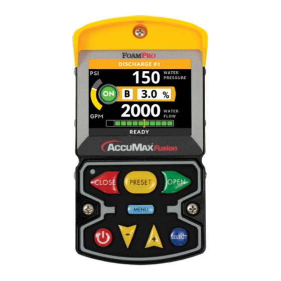
MAX100/200-OPERATION Rev200813 7. OPERATION OF SYSTEM Screen Overview On power-up the display module will be in the normal operating mode. The red ON/OFF button, yellow decrease (-)/ increase (+) buttons and blue SELECT button are used to control the foam system operation. For the MAX200 Fusion model, the green OPEN, red CLOSE, and yellow PRESET buttons will control the water valve position. - Page 18 MAX100/200-OPERATION Rev200813 Menu Button Operations The Menu is accessed by pressing and holding the MENU button. The menu system allows for the following functions: • Parameter value adjustment & modification of options • Display adjustments • Diagnostics • System Backup •...
-
Page 19: Screen View
MAX100/200-OPERATION Rev200813 Screen View Operator Screen Elements • 1. Header bar – color coded • 11. Selectable Display Value • 2. Discharge name – user defined • 12. Selectable Display Unit of Measure • 3. Error / Warning indicator (displayed only when •... - Page 20 MAX100/200-OPERATION Rev200813 Menu Screen Layout of Components (Diagram is shown on the next page.) • A—Header Bar: Current Menu/Sub menu title and icon are displayed. • B—Content Area: Displayed as a list of menu items/options. Each menu item is shown with a title, icon to the left and the current value (or status).
- Page 21 MAX100/200-OPERATION Rev200813 Menu Home Screen • A. Header bar • B3. Menu Item Icon • A1. Submenu Icon • B4. Menu Item Title • A2. Submenu Title • B5. Menu Item • A3. Admin. Access Indicator • C. Footer Bar Content Area •...
- Page 22 MAX100/200-OPERATION Rev200813 Button Functioning in Menu Screens While navigating through any of the menu screens, the keypad buttons (below the LCD display) are used to navigate, select menu items, adjust values, save and cancel changes/menu selections. Typical Button Functions: • ON/OFF button (Red) •...
- Page 23 MAX100/200-OPERATION Rev200813 Menu Functions Outline • Water Total • Water Total System DISPLAY • SELECTABLE DISPLAY • DISPLAY BRIGHTNESS: • Select Variables • Brightness Day • Foam Flow. • Brightness Night • Foam Total • DAY/NIGHT MODE • Foam Flow System •...
- Page 24 MAX100/200-OPERATION Rev200813 • FOAM FLOW INC. • Class A • FOAM FLOW M. INC. • Class B • NAME: • FOAM PUMP TYPE • Edit Name • FIRE LION 3020 • Select from List • FIRE LION 3040 • Import Name List •...
- Page 25 MAX100/200-OPERATION Rev200813 • WT. FLOW SOURCE ID MAINTENANCE • Local • VALVE CALIBRATION* • Dev. ID:1 • PRESS. CALIBRATION* • Dev. ID:2 • WATER FL. CAL. INJ. • • FOAM CAL. MASTER • HYD. CNTL BACKUP • FOAM CAL. INJ. •...
-
Page 26: Accessing Water Flow Simulation Mode
MAX100/200-OPERATION Rev200813 Accessing Water Flow Simulation Mode Press the blue SELECT button several times until "Simulated Water Flow" is displayed on selectable display at the bottom of the screen. The value on the display will read "OFF". To activate water flow simulation, press and hold the yellow UP/DOWN buttons simultaneously. -
Page 27: Setup
MAX100/200-OPERATION Rev200813 8. SETUP Setup Guidelines Initial Setup The AccuMax foam proportioning system must be properly setup before any operations can take place. AccuMax setup is conducted using Display Modules for either Fury (MAX100) or Fusion (MAX200) models. All settings and options can be set from within the Menu system. - Page 28 MAX100/200-OPERATION Rev200813 Table 1. AccuMax System Setup Process Step Device Description Menu Item Set system unit of measure All Display Set preferred system unit of measure. USER Modules SETTINGS / UNIT SYSTEM Set Display Module Unit ID All Display Set unique unit ID to each display module on the network. SETUP/ UNIT ID Modules Unit ID is used to identify and pair devices that work with specific...
-
Page 29: User Access Level
MAX100/200-OPERATION Rev200813 User Access Level To prevent unintentional parameter changes, a number of settings are only available to users with advanced access permissions. In order to gain access to these settings, an operator needs to enter their access code. NOTE: the shield icon indicates that this parameter requires an advanced user access level. - Page 30 MAX100/200-OPERATION Rev200813 Setting Module Unit ID The display module unit ID setting determines which foam injector and/or valve will be controlled by that display. Setting the module ID should only be done when a new unit is installed, or after a unit is replaced. A secondary display module can be added to operate the same foam injector and/or valve by assigning the same unit ID as the first module.
- Page 31 MAX100/200-OPERATION Rev200813 3. A list of all injectors on the CAN network will be displayed with their serial numbers and current IDs. If the menu displays 'NO ITEMS', there are no injectors on the network that can be paired. 4. Select the injector Serial Number to be paired with the display module. Any injector can be selected during the pairing process.
- Page 32 MAX100/200-OPERATION Rev200813 Pair Low-Flow NOTE: Hydraulic controllers are normally factory paired. However, pairing can be changed at any time, if there is a configuration change, or for replacement parts. Pairing process assigns the low-flow line with a group number. Group ID needs to be changed only if there is more than one AccuMax system on the same CAN Network.
- Page 33 MAX100/200-OPERATION Rev200813 6. Pairing screen will be displayed and 'TEST VALVE' item will be selected. If needed, press the SELECT or ON/ OFF button to move the valve. This will confirm that the valve chosen is the correct one. 7 To proceed with pairing, press INCREASE or DECREASE button once to select 'SAVE AND RETURN' item.
- Page 34 MAX100/200-OPERATION Rev200813 Foam Tank Size This setting defines the foam tank capacity. This number is used to calculate the amount of time until the tank is depleted at the current consumption rate. The "Foam Time to Empty" value can be selected as one parameter to be displayed on the operator's screen.
- Page 35 MAX100/200-OPERATION Rev200813 Reading Water Flow from Remote CAN Device (WT. FLOW SOURCE ID) This setting selects the water flow reading source to be local, sensor connected to injector, or remote sensor connected to another device on the CAN network. Use "LOCAL" option if the sensor is connected to the injector, or select the "DEVICE ID"...
- Page 36 MAX100/200-OPERATION Rev200813 Flow Increment Adjustment The measured flow value is displayed with default increment of 1 unit. This increment can be adjusted to suit an operator's preference. For example, if the increment is changed to 10, then the displayed value will be rounded to nearest 10. 1.
- Page 37 MAX100/200-OPERATION Rev200813 2. The current file name will be highlighted for editing with the cursor blinking. Use the SELECT button to change to the next character at the cursor position. Use ON/OFF button to select the previous character in the cursor position.
-
Page 38: User Settings
MAX100/200-OPERATION Rev200813 9. USER SETTINGS Adjusting User Settings Reset Accumulated Water and Foam Totals AccuMax hardware components measure and collect consumption data on water and foam. These numbers are recorded in an event log each time the system is turned off. These totals are automatically reset at startup. However, they can be reset at any time from the menu. - Page 39 MAX100/200-OPERATION Rev200813 7. When editing is completed, press the INCREASE or DECREASE button until the cursor reaches the end of the name field. The next press of the INCREASE or DECREASE button will select 'CLEAR' item of this screen. Or press and hold the INCREASE or DECREASE button to until the 'CLEAR' item is selected. 8.
- Page 40 MAX100/200-OPERATION Rev200813 Units of Measure (UOM) The display module can be set to display information in Imperial or Metric units of measure. Several configurations of these units are available to choose to suit the operator's preference. 1. Select USER SETTINGS on the menu screen. Press INCREASE or DECREASE button until the user setting is selected.
- Page 41 MAX100/200-OPERATION Rev200813 NOTE: If the value entered already exists as a preset, a duplicate preset will not be saved. The preset list will be updated and sorted after a new preset is added. Changing Existing Preset Value 1. Select USER SETTINGS on the menu screen by pressing INCREASE or DECREASE button until the USER SETTINGS item is selected.
- Page 42 MAX100/200-OPERATION Rev200813 4. The preset entry screen will open and the preset value field with current value will be selected. Press INCREASE or DECREASE button until the ‘SET AS DEFAULT’ item is selected. Press the SELECT button to mark this preset as the default.
- Page 43 MAX100/200-OPERATION Rev200813 2. In USER SETTINGS, select the 'SELECTABLE DISPLAY' item using the INCREASE or DECREASE button. Press the SELECT button to enter the submenu. Select Variables for Selectable Display This submenu lists all variables available for the Selectable Display. Each variable can be individually enabled or disabled for this display.
- Page 44 MAX100/200-OPERATION Rev200813 3. In SELECTABLE DISPLAY, select the 'SELECT VARIABLES' item using the INCREASE or DECREASE button. Press the SELECT button to enter the submenu. 4. List of variables will be displayed. Press INCREASE or DECREASE button to highlight desired variable. Press the SELECT button to mark the highlighted variable as the default.
- Page 45 MAX100/200-OPERATION Rev200813 Simulated Water Flow Mode Adjustment Increments These settings allow the operator to set flow rate increments to be used when unit is operating in Water Simulation Mode. Simulated water flow rate will decrease/increase by this amount when INCREASE or DECREASE buttons are pressed (minor increment) or held down (major increment).
- Page 46 MAX100/200-OPERATION Rev200813 Set Date Format This settings allows the operator to set the preferred format for date for the display and device log. 1. Select USER SETTINGS on the menu screen by pressing the INCREASE or DECREASE button. Press the SELECT button to access this menu.
-
Page 47: Display
MAX100/200-OPERATION Rev200813 Display Display Brightness The AccuMax system will automatically switch the screen appearance and brightness level to match ambient light. Brighter color scheme and higher brightness intensity is used for daylight. Darker color scheme and lower intensity is used for nighttime. Screen brightness can be adjusted individually for daytime and nighttime. 1. - Page 48 MAX100/200-OPERATION Rev200813 Day/Night Threshold Day/Night Threshold setting determines the level of ambient light required to switch day/night mode. The higher the setting, the more ambient light is required to switch to day mode. The lower the setting, the less ambient light is required to switch modes.
-
Page 49: Report Functions
MAX100/200-OPERATION Rev200813 Report Functions Report feature of the AccuMax system is used to record the consumption of water and foam concentrate by the system for each incident of system use. Incident data can be reviewed using any AccuMax display module. If needed, stored data can be exported as a CSV file and saved on an external USB device. - Page 50 MAX100/200-OPERATION Rev200813 Reviewing Recorded Incident Data Report consumption data for all recorded incidents can be reviewed by using any AccuMax Display module. Reading the recorded data from Report: 1. Select 'REPORT' item in the main menu. Press the SELECT button to access the submenu.
-
Page 51: Event Log Functions
MAX100/200-OPERATION Rev200813 Event Log Functions The AccuMax system is equipped with log feature, which records events during operation. Recorded events are: • Total Water Volume Accumulated–Recorded each time the valve is fully closed. • Parameter Change–Recorded when settings/parameters have been changed. •... - Page 52 MAX100/200-OPERATION Rev200813 3. Press the INCREASE or DECREASE button to select the desired option. Press the SELECT button to confirm the selection. 4. Press the CLOSE button to return to the previous menu. Exporting Log Files Log files can be saved to an external USB device to be read later on a computer. 1.
-
Page 53: Factory Settings
MAX100/200-OPERATION Rev200813 10. FACTORY SETTINGS Changing Factory Settings NOTE: the shield icon indicates that this parameter requires an advanced user access level. Demo Mode Demo Mode allows for demonstration of product features and functions without connecting to an actual hardware component. - Page 54 MAX100/200-OPERATION Rev200813 • UPDATE APPLICATION–New version of display module application • START UPDATE(S)–Item to execute selected updates 4. Each of the firmware updates can be disabled or enabled as needed. In order to disable any updates, select the update with the INCREASE or DECREASE button, and press the SELECT button. This will open the submenu with a selection of the available options.
-
Page 55: Diagnostics, Troubleshooting And Testing
MAX100/200-OPERATION Rev200813 11. DIAGNOSTICS, TROUBLESHOOTING AND TESTING Diagnostics Tools To assist with troubleshooting and setup, a number of diagnostic tools are available within the valve controller. Network Identification Utility This feature allows the user, within a single button press, to view the all the APEX valve controllers' network ID numbers, paired valve serial numbers and day/night mode settings. - Page 56 MAX100/200-OPERATION Rev200813 7. Select 'DIAG SCREEN' item. Press the SELECT button to display this submenu. 8. Press the INCREASE or DECREASE button until the 'DISABLE' item is selected. Press the SELECT button to select 'DISABLE' . Firmware Revision Information To determine the current software revisions, follow the steps below. 1.
-
Page 57: Active Error/Warning
MAX100/200-OPERATION Rev200813 Active Error/Warning All active error/warning codes can be reviewed when needed through the menu system. Accessing Active Error/Warning List 1. Select 'ACTIVE WARN./ERR.' from the main menu. Press the SELECT button to access the submenu. 2. If there are active errors/warnings, they will be displayed on the screen. 3. -
Page 58: Error/Warning Codes Troubleshooting Table
MAX100/200-OPERATION Rev200813 Error/Warning Codes Troubleshooting Table The table is provided to assist in tracking down system problems, it is not meant to take the place of good troubleshooting practices. Table 2. Error/Warning Codes Accumax Display Controller Errors and Warnings Code Message Description/Cause Corrective Actions... - Page 59 MAX100/200-OPERATION Rev200813 (Continued Table 2. Error/ Warnings Codes and Troubleshooting) Accumax Display Controller Errors and Warnings Code Message Description/Cause Corrective Actions E0435 INJ. INT. CIRCUIT Injector assembly internal circuit issue. Contact factory. E0436 INJ. FOAM METER Injector assembly foam flow meter issue. Check if foam flow meter cable is plugged in.
- Page 60 MAX100/200-OPERATION Rev200813 (Continued Table 2. Error/ Warnings Codes and Troubleshooting) Accumax Display Controller Errors and Warnings Code Message Description/Cause Corrective Actions W0467 SYS. NO FOAM SHUTDOWN System was shut down due to lack off foam. Reestablish foam supply. Turn Foam On to resume operation.
- Page 61 MAX100/200-OPERATION Rev200813 (Continued Table 2. Error/ Warnings Codes and Troubleshooting) Accumax Display Controller Errors and Warnings Code Message Description/Cause Corrective Actions VALVE NO MOTION Valve does not move. High current. Check motor wiring, observe if it drives valve. E0221 Internal issue with actuator. Electric motor is Contact manufacturer.
- Page 62 MAX100/200-OPERATION Rev200813 Update Remote Device Firmware (Hardware Components) The display module can be used to update the firmware of the hardware components over the CAN Bus connection. Hardware components that can be updated include: injectors, hydraulic controllers, low-flow option and water valve. The manufacturer will provide an firmware update file when needed.
-
Page 63: Calibration & Testing
MAX100/200-OPERATION Rev200813 12. CALIBRATION & TESTING Calibration Procedure Instructions The Foam Pro AccuMax foam proportioning system relies on sensor readings to control the injection rate of the foam concentrate into the water stream and for the other system functions. Proper calibration ensures that the system produces an accurate foam solution and maintains the proper and safe level of foam flow and pressure in its pump and the other components. - Page 64 MAX100/200-OPERATION Rev200813 • Final installer provided: hoses and fittings are required for external flowmeter connections and water discharge or recirculation. • Flowmeter with volume measurement capability, such as provided in the in the AccuMax Calibration Kit (P/N: 3430-0381) • Final installer provided: container marked for volume, using a container to ensure that it has enough volume capacity (300G/1000L) to calibrate at least one line.
- Page 65 MAX100/200-OPERATION Rev200813 Water Flowmeter Calibration It is critical that an accurate flow measuring device be used to measure water flow to calibrate all water flowmeter(s). Use a suitable size smooth bore nozzle and an accurate pitot gauge instrument. Determine the water flow normally expected from that discharge outlet.
- Page 66 MAX100/200-OPERATION Rev200813 Table 3. Calibration Requirements Calibrate Code Scenario Master Foam Low-Flow Injector(s) Injector(s) Water Valve Flow Foam Flow Foam Flow Water Flow Position After system installation All Injectors All Injectors All Valves Master foam flow meter is replaced All Injectors —...
- Page 67 MAX100/200-OPERATION Rev200813 Order of Calibration Process Calibration process can be divided into two groups: • Water Flow Calibrations for each water flow meter in system • Foam Flow Calibrations for master flow meter, low-flow line and injectors Each calibration group can be performed independently of the other and in any order. Water Flow Calibration Requirements The process will require running water pump and operating water valves, along with moving hose connections from each water outlet to an external flow metering device.
- Page 68 MAX100/200-OPERATION Rev200813 5. Operate water valve to establish water flow rate to be used for calibration. NOTE: For Fusion MAX200 models with water valve control. To operate water valve, press INCREASE or DECREASE buttons until ‘OPERATE VALVE’ item is selected. Use SELECT or ON/OFF buttons to move valve toward open or close position as needed.
- Page 69 MAX100/200-OPERATION Rev200813 This calibration need to be performed first before any injector foam flow meters calibrations are done. Master Foam Flowmeter will be used as reference device for injector foam flow meters calibrations. To perform this calibration the operator needs to: 1.
- Page 70 MAX100/200-OPERATION Rev200813 17. When sufficient volume has been accumulated, press the ON/OFF button to stop flow. It may take up to 15s to stop the flow and close all valves. When the system has stopped, the icon on the right side of the ‘START / STOP’ item will change to 18.
- Page 71 MAX100/200-OPERATION Rev200813 5. Make sure the hydraulic system is running and PTO is engaged. 6. Using the display module, open the main menu. 7. In the main menu select MAINTENANCE item by pressing INCREASE or DECREASE buttons. Press SELECT button to access the submenu. 8.
- Page 72 MAX100/200-OPERATION Rev200813 19. Dialog box will be displayed to confirm that the calibration was successfully completed. If the calibration fails, it will need to be repeated. 20. Depressurize and disconnect the hoses from the calibration valve. 21. Switch the calibration valve back to normal position to direct the foam flow into the water way. Low-Flow Foam Flow Calibration Low-Flow Foam Flowmeter measures the flow of foam concentrate circulated back to the foam pump inlet when low-flow is in use.
- Page 73 MAX100/200-OPERATION Rev200813 12. Values for the ‘MASTER VOLUME’ and ‘L. FLOW VOLUME’ will be displayed. 13. Press the DECREASE button to select the ‘SAVE AND RETURN’ item on the screen. 14. Press the SELECT button to update low-flow foam flow calibration. Calibration data will be automatically recalculated and updated to match the master flowmeter reading.
-
Page 74: Valve Position Calibration (For Max200 Fusion Models Only)
MAX100/200-OPERATION Rev200813 Valve Position Calibration (for MAX200 Fusion models only) The valve position calibration determines the point where the valve is fully open or fully closed. This process will automatically determine these points by running the valve to fully open position until it hits the mechanical stop, and then rotating back to the fully closed position until it reaches mechanical stop. - Page 75 MAX100/200-OPERATION Rev200813 7. Press the INCREASE or DECREASE button until 'ADD CALIBRATION POINT' has been selected. Press the SELECT button to add this data as a calibration point. A confirmation dialog box will appear to indicate this operation was successful. Should the data entry fail, repeat the process from step 6. 8.
-
Page 76: Maintenance & Service Requirements
MAX100/200-OPERATION Rev200813 13. MAINTENANCE & SERVICE REQUIREMENTS Flushing Kit Maintenance/Service Flushing Kit Installation and Controls No matter which Foam Pro system is supplied on both vehicle or fixed foam system installations, a foam concentrate “flushing” system shall be required. This system shall be furnished and installed by the final installer. Refer to the drawing below that outlines the plumbing, control valve, pressure regulator, check valve, strainer, and connecting hose from the flush kit to the intake-side of the foam pump piping. - Page 77 MAX100/200-OPERATION Rev200813 2. Foam concentrate tank control valve should be in the CLOSED position (final installer valve or FOAM-AUX CONTROL). 3. Following standard fire and foam system operating manuals and procedures, start the power source, engage the fire pump, engage the hydraulic pump system PTO or power source and establish water-flow through all foam/ water solution discharges.
- Page 78 MAX100/200-OPERATION Rev200813 • The foam strainer shall be checked and cleaned a minimum of every 6-months or after each major firefighting incident or usage. Foam Pump Maintenance and Service The AccuMax foam system is provided with a foam pump (Trident, FireLion, or Edwards) and each manufacturer has specific and recommended service and maintenance procedures.
- Page 79 MAX100/200-OPERATION Rev200813 • Drain the foam pump prior to removal from the system and close the foam tank valve. • Routine inspection and maintenance must be performed as outlined in this Operation & Service manual. • Only use lubricants and cleaning solvents listed in this manual for maintenance and repairs. Observe correct material handling procedures when working with lubricants and solvents.
-
Page 80: Component Drawings & Part Numbers
MAX100/200-OPERATION Rev200813 14. COMPONENT DRAWINGS & PART NUMBERS Line Control Assembly Dimensions and Flow Capacities STANDARD COMPONENTS -- ACCUMAX II SYSTEM ITEM Description TYPE Part ID Label, AccuMax II, Instruction Plaque Label XE-MAX1PLINST-A0A Label, AccuMax II, Plumbing Schematic Label XE-MAX1PLPLB-A0A Label, AccuMax II, 20GPM, Spec Label XE-MAX1PLSPC-A02A... - Page 81 MAX100/200-OPERATION Rev200813 CABLE ONLY COMPONENTS -- ACCUMAX II SYSTEM ITEM DESCRIPTION TYPE PART ID Cable, MAX200, Data 6 Pin x Data 3 Pin, 3 Ft. Long Data Cable XE-MAX2006DP3DP-C3A Cable, Data Bus, Extension, 3 Pin, 1 FT Long Data Bus Extension Cable XE-MAX210-DBEXT-C01B Cable, Data Bus, Extension, 3 Pin, 2 FT Long Data Bus Extension Cable...
- Page 82 MAX100/200-OPERATION Rev200813 FOAM SYSTEM COMPONENT PART NUMBERS -- ACCUMAX II SYSTEM ITEM DESCRIPTION TYPE PART ID Relief Valve, 1.5", Foam System Relief Valve 3300-0101 Wye Strainer, Foam Pump, 2", #3020 Wye Strainer 3350-0145 Wye Strainer, Foam Pump, 2", #3040 Wye Strainer 3350-0145 Wye Strainer, Foam Pump, 2", #3060 Wye Strainer...
- Page 83 MAX100/200-OPERATION Rev200813 1.0" Low-Flow Bypass Assembly and 0.5”, 1.0”, 1.5” Foam Line Injector Base Drawing (Top, Side and Front Views) FOAM LINE INJECTOR ASSEMBLIES -- Dimensions, Flow Capacities, & Part Numbers Dimensions Pipe Dmtr / Thread Item Assembly -- Part Number Description FOAM CONC Flow Range...
- Page 84 MAX100/200-OPERATION Rev200813 FOAM LINE INJECTOR ASSEMBLIES -- Dimensions, Flow Capacities, & Part Numbers Dimensions Pipe Dmtr / Thread ITEM Assembly -- Part Number Description FOAM CONC Flow Range XE-MAX210LC-K10A Foam Line Injector Assembly Kit - 1" 6-60 GPM / 27.5" 7.875"...
- Page 85 MAX100/200-OPERATION Rev200813 2.0" Foam Line Injector Drawing FOAM LINE INJECTOR ASSEMBLIES -- Dimensions, Flow Capacities, & Part Numbers Dimensions Pipe Dmtr / Thread Item Assembly -- Part Number Description FOAM CONC Flow Range XE-MAX210LC-K20A Foam Line Injector Assembly 24-300 GPM / 29”...
- Page 86 MAX100/200-OPERATION Rev200813 Water Flowmeters -- Part Numbers, Size, Abbreviations, And Descriptions Water Flowmeter Abbreviation Chart SENSOR PHOTO ABBREVIATION DESCRIPTION Stainless Steel Weldment Steel Weldment Aluminum Weldment Pipe Tee Saddle Clamp Manifold SS+FC Stainless Steel Weldment + Flow Conditioner SS+ST Stainless Steel Weldment + Shallow Throat S+FC Steel Weldment + Flow Conditioner AL+FC...
- Page 87 MAX100/200-OPERATION Rev200813 WATER FLOW SENSOR -- 2.5" SIZE WATER FLOW RATE XE-FM025AL1-M0A 2.5" Aluminum Weldment Mntg - 2.5" XE-FM025AL2-M0A 2.5" AL+FC Aluminum Weldment Mntg & Flow Conditioner - 2.5" XE-TF2FMANFL-M25A 2.5" Manifold Mntg - 2.5" XE-FM025PT1-M0A 2.5" Pipe Tee Mntg - 2.5" XE-FM025PT2-M0A 2.5"...
- Page 88 MAX100/200-OPERATION Rev200813 WATER FLOW SENSOR -- 5" SIZE WATER FLOW RATE XE-FM050AL1-M0A 5" Aluminum Weldment Mntg - 5" XE-FM050AL2-M0A 5" AL+FC Aluminum Weldment Mntg & Flow Conditioner - 5" XE-FM050PT1-M0A 5" Pipe Tee Mntg - 5" XE-FM050PT2-M0A 5" PT+FC Pipe Tee Mntg & Flow Conditioner - 5" XE-FM050ST1-M0A 5"...
- Page 89 MAX100/200-OPERATION Rev200813 HYDRAULIC & FOAM PUMP COMPONENTS -- ACCUMAX II SYSTEM ITEM DESCRIPTION TYPE PART ID Hydraulic Variable Speed Pump, #3020 Hydraulic Pump 2500-0071 Hydraulic Variable Speed Pump, #3040 Hydraulic Pump 2500-0071 Hydraulic Variable Speed Pump, #3060 Hydraulic Pump 2500-0063 Hydraulic Variable Speed Pump, #3090 Hydraulic Pump 2500-0030...
- Page 90 MAX100/200-OPERATION Rev200813 Fire Lion Pump/Motor Assembly Parts FIRELION FOAM PUMP COUPLING HYDRAULIC MOTOR FIRE LION FOAM PUMPS Foam Pump, FireLion, #3020 Foam Pump 8000-1010 Foam Pump, FireLion, #3040 Foam Pump 8000-1011 Foam Pump, FireLion, #3060 Foam Pump 8000-1012 Foam Pump, FireLion, #3090 Foam Pump 8000-1013 Foam Pump, FireLion, #3150...
- Page 91 MAX100/200-OPERATION Rev200813 Hydraulic Pump 3060...
- Page 92 MAX100/200-OPERATION Rev200813 Hydraulic Pump 3090 and 3150...
- Page 93 MAX100/200-OPERATION Rev200813 Hydraulic Pump 3300...
- Page 94 MAX100/200-OPERATION Rev200813 3020 – Fire Lion Pump/Motor Assembly (P/N 3450-1035) DISCHARGE PORT 1" GROOVED VICTAULIC Ø .56 THRU (4) HOLES 5.25 (133.35mm) 6.00 (152.4mm) (82.55mm) 3.25 6.50 (165mm) 12.00 (304.8mm) 10.50 (266.7mm) (9.6mm) 6.75 2.19 (171.5mm) (55.6mm) SUCTION PORT (80.26mm) 1"...
- Page 95 MAX100/200-OPERATION Rev200813 3040 – Fire Lion Pump/Motor Assembly (P/N 3450-1036) DISCHARGE PORT (14.2mm) Ø .56 THRU 1 1/2" GROOVED VICTAULIC (4) HOLES (38mm) 5.25 (133mm) 6.00 (152mm) 3.88 10.50 (152mm) (267mm) 7.75 (197mm) 12.00 (305mm) (216mm) 8.50 2.09 7.38 (53mm) (288mm) (187mm) 11.34...
- Page 96 MAX100/200-OPERATION Rev200813 3090 – Fire Lion Pump/Motor Assembly (P/N 3450-1038) (257mm) 10.10 CASE DRAIN 5.05 SAE -10 ORB (128mm) SUCTION PORT DISCHARGE PORT 2" GROOVED VICTAULIC 2" GROOVED VICTAULIC CASE DRAIN SAE -10 ORB (12.7mm) 11.54 (293mm) 16.95 (431mm) PORT A 26.47 2.95 (672mm)
- Page 97 MAX100/200-OPERATION Rev200813 3300 – Fire Lion Pump/Motor Assembly (P/N 3450-1040) (292mm) 11.50 CASE DRAIN 5.75 7/8-14 UNF-2B (146mm) SAE -10 ORB SUCTION PORT 4" GROOVED VICTAULIC DISCHARGE PORT 4" GROOVED VICTAULIC 11.75 (298mm) 10.93 (278mm) 6.25 4.69 (119mm) (298mm) 4.35 (110mm) (84.1mm) 3.31...
- Page 98 MAX100/200-OPERATION Rev200813 Edwards Parts Identification Pump/Motor Assembly EDWARDS FOAM PUMP COUPLING HYDRAULIC MOTOR EDWARDS FOAM PUMPS Foam Pump, Edwards, #3020 Foam Pump 8000-0075 Foam Pump, Edwards, #3040 Foam Pump 8000-0076 Foam Pump, Edwards, #3060 Foam Pump 8000-0077 Foam Pump, Edwards, #3090 Foam Pump 8000-0078 Foam Pump, Edwards, #3150...
- Page 99 MAX100/200-OPERATION Rev200813 3020 & 3040 – Edwards Pump/Motor Assembly (P/N 3450-0071 & 3450-0072) [663] 26.1 [481] 19.0 [197] [80] [211] [40] 1-1/2" NPT [95] Outlet Port 1-1/2" NPT Inlet Port [127] [83] [181] [248] Port A 1-1/16"-12 Straight Thd Port B O-Ring Port 1-1/6"-12 [114]...
- Page 100 MAX100/200-OPERATION Rev200813 3090 – Edwards Pump/Motor Assembly (3450-0074) Port A 1.0625-12 SAE Str.Thd. O-ring Boss Case Drain 1" Split Flange Boss SAE J518 (Code 62) [83.6] Port B 1" Split Flange Boss [445.59] SAE J518 (Code 62) 17.54 [531.44] 20.92 [234.95] [789.25] 9.25...
- Page 101 MAX100/200-OPERATION Rev200813 3300 – Edwards Pump/Motor Assembly (3450-0076) 1" SAE Split Flange 1.0625 SAE Str.Thd. Port A Case Outlet [84] 1" SAE Split Flange [489] Port B [248] 19.2 [582] 22.9 [871] 34.3 3" NPT Inlet [614] 24.2 3" NPT Outlet [307] 12.1 [142]...
- Page 102 MAX100/200-OPERATION Rev200813 Trident Pump/Motor Assembly Parts TRIDENT FOAM PUMP COUPLING HYDRAULIC MOTOR TRIDENT FOAM PUMPS Foam Pump, Trident, #3020 Foam Pump 8000-1018 Foam Pump, Trident, #3040 Foam Pump 8000-1019 Foam Pump, Trident, #3060 Foam Pump 8000-1019 Foam Pump, Trident, #3090 Foam Pump 8000-1020 Foam Pump, Trident, #3150...
- Page 103 MAX100/200-OPERATION Rev200813 3020 – Trident Pump/Motor Assembly (P/N 3450-1041) Sunction Port 3" Grooved Victaulic (80.26mm) Discharge Port 1-1/2" NPT 3" Grooved Victaulic 3.16 Outlet Port 1.57 (39.88mm) 1-1/2" NPT Inlet Port 8.56 (217.42mm) 8.10 (205.74mm) (133.35mm) 5.25 4.00 (88.9mm) 3.50 (101.6mm) 3.875 9.47...
- Page 104 MAX100/200-OPERATION Rev200813 3090 – Trident Pump/Motor Assembly (P/N 3450-1044) (203mm) 8.00 CASE DRAIN PORT SAE -10 ORB 12.51 (318mm) 9.25 (235mm) 2" VICTAULIC SUCTION PORT 2" VICTAULIC DISCHARGE PORT 5.63 (143mm) CASE DRAIN PORT SAE -10 ORB PORT A 12.38 3/4"...
- Page 105 MAX100/200-OPERATION Rev200813 3300 – Trident Pump/Motor Assembly (P/N 3450-1046) SUCTION PORT DISCHARGE PORT 4" GROOVED VICTAULIC 4" GROOVED VICTAULIC (203mm) 8.00 4.00 (102mm) CASE DRAIN SAE -10 ORB 12.51 (318mm) 5.63 (143mm) CASE DRAIN SAE -10 ORB (140mm) 5.50 (368mm) 14.47 11.00 PORT A...
- Page 106 MAX100/200-OPERATION Rev200813 Limited Warranty Fire Research Corp. (FRC), as supplier of FoamPro, warrants to the original purchaser, each new pump, system or other product of its own manufacture, for a period of two years from the date of shipment from the factory, to be free from defects in material and workmanship under normal use and service.
- Page 107 MAX100/200-OPERATION Rev200813 NOTES...
- Page 108 MAX100/200-OPERATION Rev200813...
Need help?
Do you have a question about the FoamPro Accumax II Fury and is the answer not in the manual?
Questions and answers