Traulsen G Series Manual
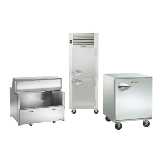
R&a refrigerator, freezer, dual-temp and hot food units
Hide thumbs
Also See for G Series:
- Service manual (78 pages) ,
- Owner's manual (24 pages) ,
- Quick start manual (2 pages)
Table of Contents
Advertisement
Advertisement
Table of Contents
Troubleshooting

Related Manuals for Traulsen G Series


Summary of Contents for Traulsen G Series
- Page 1 MASTER SERVICE MANUAL For All Full Size Undercounter, G-Series and R&A Refrigerator, Freezer, Dual-Temp and Hot Food Units Traulsen 4401 Blue Mound Road Fort Worth, Texas 76106 Phone: (800) - 825 - 8220 Part Number 375-60351-00 Form Number TR36015 revised 3/17...
- Page 2 Traulsen provides this manual as an aid to the service technician in installation, operation and maintenance of Traulsen units from year 2010 to present. When used properly. This service manual can help the service technician maintain, troubleshoot and diagnose most of the problems and malfunctions that may occur with the controllers.
-
Page 3: Table Of Contents
Intela-Traul Control System Overview b. Intela-Traul Alarm Codes from 2010 to present c. Control Access & Programming d. Troubleshooting Traulsen Intela-Traul Sensors e. Troubleshooting Traulsen Intela-Traul MIT II relay module f. RH Sensor Module Section II Refrigeration System a. Troubleshooting Traulsen Refrigeration System b. -
Page 4: Section I
Section I Intela-Traul Control System... -
Page 5: Intela-Traul Control System Overview
I. a – Intela-Traul Control System Overview Intela-Traul Components: Component Description Control Head • Microprocessor Control • User Interface Relay Module • DC Power Supply • Blower Relay • Defrost Heater Relay • Door Frame Heater Relay • Supplies 12VDC to Compressor Relay Hybrid Relay •... -
Page 6: Intela-Traul Alarm Codes From 2010 To Present
I. b - Intela-Traul Alarm Codes from 2010 to present Alarm Description Clear Alarm Refrigeration System Low Charge Repair Refrigeration System Return Cabinet Temperature to Low Cabinet Temperature Alarm Normal Range Return Cabinet Temperature to High Cabinet Temperature Alarm Normal Range Door Open Alarm Close Door Power Loss Alarm... - Page 7 I. c – Intela-Traul Control Access & Parameters To access the engineering/service menu follow the instruction below. As seen in Figures 1 & 2. INTELA-TRAUL Key Parameters INTELA-TRAUL Access Parameter Description Press Display Press Set Point Set Point Differential Set Point High (Equip Prior to 2010 only) Set Point Low (Equip Prior to 2010 only)
-
Page 8: Troubleshooting Traulsen Intela-Traul Sensors
I. d - Troubleshooting Traulsen Intela-Traul Sensors Sensor Function: • Cabinet Sensor (Green): The Cabinet sensor reads the temperature of the return air and relays that value back to the control head. The control head either cycles the compressor on or off depending on the temperature set points. If cabinet sensor reads 60⁰F (15 ⁰C) or higher the unit will not go into defrost and you can’t put into manual... - Page 9 I. d - Troubleshooting Traulsen Intela-Traul Sensors Quick Reference Table 6 Item Details • Green • Control parameter • Reads return air • Compressor cycles off of cabinet sensor value Cabinet Sensor • If cabinet sensor reads 60⁰F (15 ⁰C) or higher the unit will not go into defrost and you can’t put into manual...
- Page 10 I. d - Troubleshooting Traulsen Intela-Traul Sensors Advanced Trouble Shooting Tips There are a variety of reasons for the symptoms listed in Table 7. This troubleshooting table is intended to address the most common reasons associated with the Intela-Traul sensors only.
-
Page 11: Troubleshooting Traulsen Intela-Traul Mit Ii Relay Module
I. e - Troubleshooting Traulsen Intela-Traul MIT II Relay Module Relay Module Function: The Traulsen Relay Module is a long black rectangular box approximately 2 x 2 x 7 inches (5.08 X 5.08 X 17.08 centimeters) located behind the controller (front panel display) that contains several switching relays. - Page 12 I. e - Troubleshooting Traulsen Intela-Traul MIT II Relay Module Relay Module Control Voltage (Cont): Pin No. Color Signal Gray Blower Orange Door Heater Green Alarm From Controller Black Return to Horn Unused Unused White/Purple -RS485 Black Ground White 12vac...
-
Page 13: Rh Sensor Module
I. f - RH Sensor Module The Intela-Traul RH module (Relative Humidity Sensor) is found on the Traulsen Energy Star rated units, from October 2014 to the present. This technical bulletin may not cover all the situations that may arise in the field and final diagnosis of field based equipment is the sole responsibility of the technician contracted to perform any work required. -
Page 14: Refrigeration System
Section II Refrigeration System... - Page 15 This is to inform the field how to trouble shoots the refrigeration system with the use of a thermometer. As seen in Figure 5. Trouble Shooting Refrigeration System by Temperature: Use Table 10 and corresponding chart (Figure 5) to aid in troubleshooting a Traulsen refrigeration system with the use of thermometers. ITEM...
-
Page 16: Txv Troubleshooting
II. b - TXV Troubleshooting Standard Operating Parameters: (As measured in Figure 5, Page 14) • Superheat – 7⁰F (-13.9⁰C) • Subcooling – 4 F-12 F (-15.5⁰C TO -11.1⁰C) Troubleshooting: Superheat Subcooling Diagnosis Above 7F Below 4F Refrigerant Charge is Low Below 5F Above 12F System Overcharged... -
Page 17: Troubleshooting A Frozen Evaporator Coil
Table 12 is intended to aid in diagnosing the root cause of a frozen evaporator coil on a Traulsen upright reach-in refrigerator or freezer. This may not cover all situations that may arise in the field and final diagnosis of field based equipment is the sole responsibility of the technician contracted to perform any work required. -
Page 18: Compressor Troubleshooting
II. d - Compressor Troubleshooting Tools Required: • Basic hand tools • Clamp around amp meter • Volt Ohm meter • Basic 3 in 1(1/2 HP) Terminology: • OEM – Original Equipment Manufacturer – Refers to the manufacturer of a piece of equipment or component. - Page 19 II. d - Compressor Troubleshooting Basic Troubleshooting: • What is my amp draw and voltage when the compressor is starting? • What is the resistance of the windings? • What is the RLA (Rated Load Amps) of the compressor? • What is the LRA (Locked Rotor Amps) of the compressor? •...
-
Page 20: Compact & Milk Cooler Controls
Section III Compact & Milk Cooler Controls... - Page 21 III. a - Danfoss Control Parameters See corresponding tables below for Danfoss Control Parameters Danfoss control parameters: COMPACT FREEZER (ULT) COMPACT REFRIGERATOR (UHT) SET POINT RANGE: -10F(-23C) to +5F(-15) SET POINT RANGE: 29F(-1C) to 37F(2C) SET POINT: -3F(-3C) SET POINT: 32F(0C) DEFROST TYPE: ELECTRIC...
- Page 22 III. b - Danfoss Control Troubleshooting DANFOSS SENSOR OHM VALUES Sensor Temperature Ohm value 16.00 Ω Cabinet sensor (S1) 32⁰ (0⁰C) 16.00 Ω Coil Sensor (S2) 32⁰ (0⁰C) 4-26 Ω (slight tolerance) Spindle (S3) Table 17 Note: If the red light starts flashing this indicates a sensor failure. To start manual defrost: 1.
-
Page 23: Milk Cooler Temperature Checklist
III. c - Milk Cooler Temperature Checklist This is to inform the field of basic operational check points related to temperature maintenance concerns to understand prior to troubleshooting the refrigeration system function. Troubleshooting checklist ✓ What is the walk-in cooler/milk storage cooler temp? Best Better 33F (1C) 36F (2C) 39F (4C) 41F (5C) -
Page 24: Preventive Maintenance
Section IV Preventive Maintenance... - Page 25 Pull gasket with hand and visually inspect gasket (s) for tear, Inspection dirt, mold or worn gasket. Replace as needed. The model and serial number is required when placing a parts order call the Traulsen Parts Department at 800-825-8220. Table 20...
- Page 26 IV. a - Preventative Maintenance CLEAN CONDENSER COIL Disconnect electrical power supply before cleaning any parts of the unit. Long reliable service life Frequency Every 3 Months Time required 5 minutes to prepare 15 minutes to complete For All Upright Cabinets, remove the two bottom screws securing the louver panel, and then pivot this upwards allowing full access to the front facing condenser.
-
Page 27: Door Frame Heater Installation
Section V Door Frame Heater installation... - Page 28 V. a - Door Frame Heater Replacement Installation process: Note: The original heater wire will be abandoned in the foam. • Unplug unit. • Remove screws and breaker strips around the perimeter of the door opening. As seen in Figure 6. Figure 6 •...
- Page 29 • Use a long probe or screw driver to create a hole through the foam in the top center mullion area up to the wire chase hole. As seen In Figure 8. Figure 8 • In the wire chase check for the white and orange wires coming from the relay module.
- Page 30 • When finished reinstall breakers strips. As seen in Figure 11. Figure 11 • Plug in unit.
-
Page 31: Door Frame Heaters In Roll-In Units
V. b - Door Frame Heaters in Roll-In Units In Figure 12 How door frame heaters should be run in a two section Roll-in unit. Door Frame Heater Connector Figure 12... -
Page 32: Door Frame Heaters In Half Height Units
V. c - Door Frame Heaters in Half Height Units In Figure 13 How door frame heaters should be run in a Half Height unit. Use a long probe to create a hole Door Frame through the foam in the top center Heater mullion. - Page 33 Section VI General Wiring Diagrams...
- Page 34 VI. a – G/R/A Series Reach-In...
-
Page 35: Uht Danfoss Series
VI. b - UHT Danfoss Series... -
Page 36: Ult Danfoss Series
Vl. c - ULT Danfoss Series... -
Page 37: Milk Cooler Danfoss Series
VI. d - Milk Cooler Danfoss Series... -
Page 38: G-Series Control (Blue Display)
Section VII G-Series Control (Blue Display) - Page 39 VII. a – Control Overview Display overview Esc or Back key Unlock symbol Status icons + or Next key Unlock or Modify Cabinet Temp - or Previous key Display or Enter Figure 1 Control button legend: UNLOCK OR MODIFY KEY PLUS/NEXT KEY MINUS/PREVIOUS KEY EXIT/BACK KEY...
- Page 40 Turning the Display On and Off: Press Display Display State Hold 5 sec NO DISPLAY NORMAL DISPLAY Adjusting Temperature Set Point: 1. Unlock Keypad 2. Use to adjust Set Point 3. Press Initiate Manual Defrost: Press Display & Hold for 5 Seconds...
- Page 41 VII. b – Service Parameters Service Menu: The Service Menu contains 3 sub menus: • (Sensor) – Enables a technician to view various control & sensor statuses. • (Set) – Allows a technician to change various control parameters. • (Alarm) – Enables a technician to view various alarm states ACCESS CODE 555 Press Display...
- Page 42 Parameter Tables: 1. To view Parameter press 2. Press to return to Parameter list Mnemonic Parameter Description Time Set Local Time Set RH Snr Reset Reset Count RH Sensor Light Status Cabinet Light Off/On Aux. Device Status Auxiliary Device Status Light Status Of Lights Door Open Count...
- Page 43 Parameter Tables (Cont): 1. To access Parameter press 2. Press to unlock parameter 3. Use to adjust Parameter 4. Press to save settings 5. Press to return to Parameter list Mnemonic Parameter Description Temp Cab SP Temp Set point Daylight Savings Daylight Savings time Time Zone Time Zone...
- Page 44 Parameter Tables (Cont): 1. To view Parameter press 2. Press to return to Parameter list Mnemonic Parameter Description Temp Cab At Power Up Cabinet Temp at power up Temp Cab Alarm Cabinet Temp Alarm Status Temp Liq Line Alarm Liq Line Temp Alarm Status Liq Line SD Alarm Liq Line Shutdown Status Table 3...
- Page 45 VII. c – Display Errors Error Codes: Communication Error Corrective Actions • Press the reset button on the Main Board or power cycle the unit • Replace the cable between the Main Board and the Display • Replace the Display •...
-
Page 46: Control Overview
VII. d – Control Board Detail Control board overview: RESET BUTTON RH SNR (B), DOOR SWITCH (W) DIGITAL INPUT (BL) Figure 2 Control board Troubleshooting: Note: All components may be tested with direct power ONLY when disconnected from the board. DO NOT jumper power at the board. LED indicators will illuminate when the control is calling for an output to be energized. - Page 47 Control Board Specifications: Fuse 325/326 Series Lead-Free 3AB, Slo-Blo 20A fuse To reboot the board press the reset button (See Figure 2) for 5 seconds or until all the Reset LED lights flash, shut off and then come back on again. Toggle Toggle switch disconnects power to all controls and components.
-
Page 48: R/A-Series Control (Green Display)
Section VIII R/A-Series Control (Green Display) -
Page 49: Control Overview
VIII. a – Control Overview Display overview BUTTON SYMBOL DESCRIPTION STATUS DESCRIPTION SYMBOL Escape /Back /Cancel Key Compressor Status / Heater Status (On Hot Food cabinets only) Fan Status Minus (-) / Previous Key Plus (+) / Next Key Defrost Status Alarm/Door Open Enter / Modify Key... - Page 50 VIII. b – Control Programing Changing the Setpoint: Press Display Press Display Submenu 1/5 Submenu 2/5 Sensor Readings Settings Enter Password Enter Password Enter Password Enter Password TempCabSp Use the plus and Press enter to minus keys to modify the navigate to your setpoint.
- Page 51 Submenu 1/5 Parameters: Parameter Name Password Level Description TempCab Cabinet Temp TempEvap Evaporator Coil Temp TempLiqLine Liquid Line Temp DoorSwitch Door Switch LightSwitch Light Switch ControlTime Unit Time TempAux Auxillary Temp TempRoom Ambient Temp HumidityRoom Humidity Temp DewpointRoom Dewpoint Temp RhSensorStatus Rh Sensor Status Current...
- Page 52 Submenu 2/5 Parameters: Parameter Name Password Level Description TempCabSp Temp Setpoint TempCabSPDiff Cabinet Temp Differential TempAuxSp Aux Temp Setpoint TempAuxSPDiff Aux Temp Setpoint Dif CabFanMode Fan Mode CabFanDoorAction Evap Fan When Door Open DefrostSP Defrost Setpoint DefrostMode Defrost Mode DefrostInterval Interval Between Defrosts DefrostTime1 Defrost Time 1...
- Page 53 Submenu 3/5: Parameter Name Password Level Description Start Defrost Start Defrost Submenu 4/5: Parameter Name Password Level Description Door Alarm Door Switch Alarm TempCabAtPowerUp Cabinet Temp at power up TimeOfPowerDown Time of power down TimeOfPowerUp Time of power up PFDuration Duration of Power Failure PowerFailAlarm Power Fail Alarm...
-
Page 54: Control Board Detail
VIII. c – Control Board Detail Control board overview: RESET BUTTON RH SNR (B), DOOR SWITCH (W) DIGITAL INPUT (BL) Figure 2 Control board Troubleshooting: Note: All components may be tested with direct power ONLY when disconnected from the board. DO NOT jumper power at the board. LED indicators will illuminate when the control is calling for an output to be energized. - Page 55 Control Board Specifications: Fuse 325/326 Series Lead-Free 3AB, Slo-Blo 20A fuse To reboot the board press the reset button (See Figure 2) for 5 seconds or until all the Reset LED lights flash, shut off and then come back on again. Toggle Toggle switch disconnects power to all controls and components.
Need help?
Do you have a question about the G Series and is the answer not in the manual?
Questions and answers