Sign In
Upload
Manuals
Brands
WAGO Manuals
Circuit breakers
787-1668/0000-0080
WAGO 787-1668/0000-0080 Manuals
Manuals and User Guides for WAGO 787-1668/0000-0080. We have
1
WAGO 787-1668/0000-0080 manual available for free PDF download: Manual
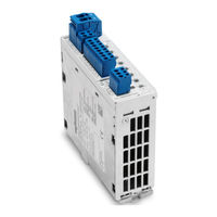
WAGO 787-1668/0000-0080 Manual (58 pages)
Electronic Circuit Breaker DC 24 V, 8 × 1 ...10 A
Brand:
WAGO
| Category:
Circuit breakers
| Size: 5 MB
Table of Contents
Table of Contents
3
1 Notes about this Documentation
5
Copyright
5
Symbols
6
Number Notation
8
Font Conventions
8
Table 1: Number Notation
8
Table 2: Font Conventions
8
2 Important Notes
9
Legal Bases
9
Subject to Changes
9
Personnel Qualifications
9
Use of the 787 Series in Compliance with Underlying Provisions
9
Technical Condition of Specified Devices
10
Safety Advice (Precautions)
11
3 Device Description
14
Table 3: Channel Fuse Protection
14
Table 4: Definition of Terms
14
View
15
Figure 1: View of Device
15
Table 5: Key for "Device View" Figure
15
Connectors
16
Power Supply
16
Figure 2: 24 V Input
16
Figure 3: 0 V Input
16
Table 6: Power Supply Connections
16
Table 7: Power Supply Connections
16
Fuse-Protected Outputs
17
Communication
17
Figure 4: Fuse-Protected Outputs Ch1
17
Figure 5: Communication Contacts
17
Table 8: Connections - Fuse-Protected Outputs
17
Table 9: Communication
17
Display Elements
18
Figure 6: Display Elements
18
Table 10: Display Elements
18
Operating Elements
19
Button
19
Figure 7: Button
19
Rotary Switch
20
Figure 8: Rotary Switch
20
Technical Data
21
Device Data
21
Table 11: Device Data
21
Technical Data for "Input
22
Table 12: Technical Data for "Input
22
Technical Data for "Output
23
Table 13: Technical Data for "Output
23
Technical Data for "Ambient Conditions
24
Technical Data for "Signaling
24
Technical Data "Communication
24
Table 14: Technical Data for "Ambient Conditions
24
Table 15: Technical Data for "Signaling
24
Table 16: Technical Data for "Communication
24
Approvals
25
Standards and Guidelines
26
4 Mounting
27
Mounting the Device on the DIN 35 Rail
27
Figure 9: Mounting the Device on the DIN 35 Rail
27
Figure 10: Mounting the Device on the DIN 35 Rail
27
Removing the Device from the DIN 35 Rail
28
Figure 11: Removing the Device from the DIN 35 Rail
28
Figure 12: Removing the Device from the DIN 35 Rail
28
5 Connect Devices
29
Connection Example
29
Figure 13: Connection Example
29
6 Function Description
30
Undervoltage and Overvoltage Detection
30
Tripping Characteristics
30
Figure 14: Tripping Characteristics
30
Activating Capacitive Loads
31
Reference Values for 787-1668/0000-0080
31
Table 17: Reference Values for 787-1668/0000-0080
31
General Operating Statuses
32
Table 18: General Operating Statuses
32
Figure 15: General Operating Statuses
33
ON Delay for Specific Channels
34
Status Query Via Channel 8" Function
35
7 IO-Link Interface
36
Cyclic Process Data
36
Output Data
36
Table 19: Byte 1 - Collective Messages for All Channels
36
Table 20: Byte 2 - Confirmation Byte for Data Transmission to the IO-Link Master
36
Table 21: Bytes 3
37
Table 22: Bytes 3
37
Input Data
38
Table 23: Byte 1 - Commands for the Electronic Circuit Breaker (Switch ON, Switch OFF, Reset)
38
Table 24: Byte 2 - Configuration Byte for Data Transmission to the IO-Link Master
38
Table 25: Byte 3 - Validation Bits
40
Table 26: Possible Combinations for the Optional Process Data
40
Acyclic Data
42
Table 27: Overview of Acyclic Data
42
Table 28: Status Query (Index 64)
43
Table 30: Device ID (Index 69)
43
Table 31: Reset Commands for the Trip Counter (Index 71)
43
Table 32: Configuration Commands for Trip Current (Index 310
43
Table 33: Status of the Electronic Circuit Breaker (Index 601
44
Table 34: Switching Commands (Index 609
44
IODD" Device Description File
45
Graphical User Interface
45
Identification" Menu Item
46
Figure 16: "Identification" Menu Item
46
Parameters" Menu Item
47
Figure 17: "Parameters" Menu Item
47
Table 29: Configuration Process Data Bytes 3
48
Table 35: "Parameters" Menu Item
48
Observation" Menu Item
49
Figure 18: "Observation" Menu Item
49
Diagnosis" Menu Item
50
Figure 19: "Diagnosis" Menu Item
50
Table 36: "Diagnosis" Menu Item
50
Process Data" Menu Item
51
Figure 20: "Process Data" Menu Item
51
Table 37: "Process Data" Menu Item
51
Process Data Structure" Menu Item
52
Figure 21: "Process Data Structure" Menu Item
52
Table 38: "Process Data Structure" Menu Item
52
Events" Menu Item
53
Figure 22: "Events" Menu Item
53
Info" Menu Item
54
Figure 23: "Info" Menu Item
54
Connection Info" Menu Item
55
Figure 24: "Connection Info" Menu Item
55
List of Figures
56
List of Tables
57
Advertisement
Advertisement
Related Products
WAGO EPSITRON 787-1668 Series
WAGO EPSITRON 787-1668/0006-1000
WAGO EPSITRON 787-1668/0106-0000
WAGO 787-2861 Series
WAGO 787-2861/0200-0000
WAGO 787-2861/0400-0000
WAGO 787-2861/0800-0000
WAGO 787-2861/0108-0020
WAGO 787-3861/800-000
WAGO 787-3861/100-1000
WAGO Categories
I/O Systems
Control Unit
Power Supply
Switch
Controller
More WAGO Manuals
Login
Sign In
OR
Sign in with Facebook
Sign in with Google
Upload manual
Upload from disk
Upload from URL