
Related Manuals for Aereco AWN ECO+ Series


Summary of Contents for Aereco AWN ECO+ Series
- Page 1 TECHNICAL MANUAL INSTALLATION AND MAINTENANCE INSTRUCTIONS AWN ECO+ Original operating instructions TF7039GB_A_NOT...
- Page 2 TF7039GB_A_NOT Dear customer, We would like to thank you for choosing an Aereco product. It is a product based on many years’ experience and careful project studies, and has been manufactured using high-quality materials and the latest technol- ogy. Furthermore, the CE designation guarantees that the units meet the requirements of the Machinery Directive (2006/42/EC) with regard to safety.
-
Page 3: Table Of Contents
TF7039GB_A_NOT Table of contents GENERAL INFORMATION ......................... 6 SCOPE OF APPLICATION ......................6 INSTRUCTIONS FOR USE ......................6 INTENDED USE ..........................7 SAFETY REGULATIONS ........................8 UNIT DESCRIPTION ........................... 9 TYPE PLATE..........................9 LOAD-BEARING CONSTRUCTION AND ERECTING DEVICE ........... 9 UNIT STRUCTURE ........................ - Page 4 TF7039GB_A_NOT 6.2.6. OPTIONS ..........................31 INTEGRATION IN THE BUILDING HEATING SYSTEM..............33 RECOMMENDATION AND SYSTEM DIAGRAM ............... 33 7.1.1. SETTINGS FOR USE WITH STRATIFIED STORAGE ............34 7.1.2. SETTINGS FOR USE WITHOUT STRATIFIED STORAGE ..........34 OPERATING RANGE AND OPERATING LIMITS ..............35 7.2.1.
- Page 5 TF7039GB_A_NOT Product designation: AWN Eco+ 111 / AWN Eco+ 121 / AWN Eco+ 131 Type: Constant-pressure-controlled exhaust air unit with integrated, source-controlled exhaust air/water heat pump Application purpose: Exhaust air conveyance and simultaneous use of exhaust air heat in outdoor areas in collective dwellings.
-
Page 6: General Information
Any use not ex- pressly stated in this manual shall not be permitted. Any contractual and extra-contractual liability of Aereco for damage to persons, animals or property as a result of installation, adjustment and maintenance errors or improper use shall be excluded. -
Page 7: Intended Use
TF7039GB_A_NOT INTENDED USE This unit is designed for use as an exhaust air heat pump in multi-storey residential buildings. It may only be operated in exhaust air systems with normal air (low dust content) up to 40°C conveying medium temperature. For proper and efficient use, the unit requires a minimum exhaust air volume that is always present (see the Technical data/minimum exhaust air volume flow section). -
Page 8: Safety Regulations
TF7039GB_A_NOT SAFETY REGULATIONS The unit is not a complete machine and is therefore not a ready-to-use product. It may only be operated if it is connected to an air conditioning system and a permissible heat sink in accordance with these instructions. Assembly, electrical installation and repair may only be carried out by trained specialist personnel. -
Page 9: Unit Description
TF7039GB_A_NOT UNIT DESCRIPTION The AWN Eco+ is an exhaust fan with integrated exhaust air heat pump for outdoor installation. The exhaust fan is intended for conveying exhaust air from apartments at a constant negative pressure. The AWN Eco+ continuously adjusts its output to the existing exhaust air volume flow. The unit includes a water-cooled heat pump that operates with R410A refrigerant in a hermetic cooling circuit with inverter rotary piston compressor. -
Page 10: Unit Structure
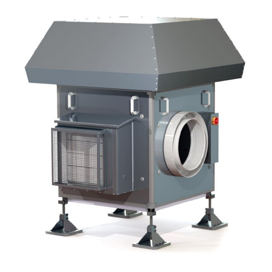
TF7039GB_A_NOT UNIT STRUCTURE 4.3.1. POSITION OF KEY COMPONENTS Stand Evaporator Plate heat exchanger Filter monitoring differential pressure switch Air filter Main switch Bypass (multi-leaf damper) Smoke detector Control unit Compressor housing Page 10 of 48... -
Page 11: Position Of The Media Connections
TF7039GB_A_NOT 4.3.2. POSITION OF THE MEDIA CONNECTIONS Exhaust air connection The unit has a pipe connection (DN 355 for Eco+ 111 and Eco+ 121 & DN560 for Eco+ 131) in the exhaust air panel next to the main switch. The exhaust air from the collecting pipe is fed into the unit via this connection. -
Page 12: Size Of The Media Connections
TF7039GB_A_NOT 4.3.3. SIZE OF THE MEDIA CONNECTIONS • Eco+ 111 and Eco+ 121 Connection Size Number Exhaust air connection 355 mm (DN) 1” IG Heating water supply (AWN) 1” IG Heating water return (AWN) Condensate drain 16 mm Metal composite pipe •... -
Page 13: Unit Dimensions
TF7039GB_A_NOT UNIT DIMENSIONS 4.4.1. HOUSING DIMENSIONS Eco+ 111 : Eco+ 121 : Page 13 of 48... -
Page 14: Stands For Eco+ 111 ; Eco+ 121 And Eco+ 131
TF7039GB_A_NOT Eco+ 131 : 4.4.2. STANDS FOR ECO+ 111 ; ECO+ 121 AND ECO+ 131 Page 14 of 48... -
Page 15: Integrated Components
TF7039GB_A_NOT INTEGRATED COMPONENTS The integrated components of the heating circuit and cooling circuit are shown in the following flow diagrams. Cooling circuit Compressor with inverter control Condenser Refrigerant collector Filter dryer Sight glass with humidity indicator Thermostatic expansion valve Evaporator LP controller Motor protection 10 HP controller... -
Page 16: Exhaust Air Conveyance Components
TF7039GB_A_NOT 4.5.1. EXHAUST AIR CONVEYANCE COMPONENTS EC centrifugal fan (curved backward) for conveying exhaust air Differential pressure control Control module for measuring the generated negative pressure in the intake chamber in relation to the envi- ronment and corresponding control of the fan speed in order to achieve the adjustable target value. Air filter Class G4 air filter to protect the heat exchanger from contamination Filter monitoring differential pressure switch... -
Page 17: Heating Water Circuit Components
TF7039GB_A_NOT 4.5.3. HEATING WATER CIRCUIT COMPONENTS SAFETY VALVE (3 BAR) In the event of pressure faults in the heating water pipes, a safety valve is triggered and excess pressure is released. This can be connected to a drain on site. VENTILATION VALVE Used to manually vent the system. - Page 18 TF7039GB_A_NOT ELECTRONIC CONTROL (UVR 1611) The unit control panel allows plant operating parameters to be adjusted quickly and intuitively. The display shows various indications of the operating mode, set parameters and any alarms triggered. All standard settings and any changes are saved in the controller control panel. After a power failure, the unit is able to restart automatically and retains the original settings.
-
Page 19: Technical Data
TF7039GB_A_NOT TECHNICAL DATA Eco+ 111: DIMENSIONING INFORMATION Installation site Outside Pressure increase for dimensioning Max. flow rate for dimensioning (75%) at 130 Pa m³/h 2.400 Heating capacity modulation range (A20W35) 2,5-8,4 Corresponding modulation range exhaust air m³/h 480-1.800 Min. required effective exhaust air volume flow m³/h Max. - Page 20 TF7039GB_A_NOT Eco+ 121: DIMENSIONING INFORMATION Installation site Outside Pressure increase for dimensioning Max. flow rate for dimensioning (75%) at 130 Pa m³/h 2.400 Heating capacity modulation range (A20W35) 3,2-10,4 Corresponding modulation range exhaust air m³/h 630-2.500 Min. required effective exhaust air volume flow m³/h Max.
- Page 21 TF7039GB_A_NOT Eco+ 131: DIMENSIONING INFORMATION Installation site Outside Pressure increase for dimensioning Max. flow rate for dimensioning (75%) at 130 Pa m³/h 3.375 Heating capacity modulation range (A20W35) 6,6 - 22,2 Corresponding modulation range exhaust air m³/h 1.250 - 4.500 Min.
-
Page 22: Receiving And Moving The Unit
TF7039GB_A_NOT All data for exhaust air at 20°C and 50% rel. humidity and for water. Data according to EN 14511:2013 RECEIVING AND MOVING THE UNIT The unit is shipped ex works wrapped in foil on a pallet. Pay attention to possible damage to the packaging or the exhaust fan. -
Page 23: Connections To Be Provided By The Customer
TF7039GB_A_NOT TECHNICALLY REQUIRED MINIMUM DISTANCES To allow regular and extraordinary maintenance work on the unit, minimum distances from walls, railings, other appliances or similar obstacles must be provided on all sides of the unit. If the unit is inadequately fixed, it may come loose and start moving. There is a danger of per- sonal injury or damage to property. -
Page 24: Handling The Unit
TF7039GB_A_NOT HANDLING THE UNIT The unit is bolted to a pallet for transport. With suitable transport equipment, the unit can be transported on this pallet for all logistical processes except lifting onto the roof. Free lifting of the unit (e.g. when lifting to the roof) may only be carried out using the eye bolts provided on the top of the unit. -
Page 25: Condensate Drain Connection
TF7039GB_A_NOT To compensate for slight unevenness, the device has height- and angle-adjustable feet. The unit is approved exclusively for instal- lation on flat roofs. If it is not possible to adjust the feet sufficiently to ensure horizontal alignment, further measures must be checked by the customer. -
Page 26: Lightning Protection
TF7039GB_A_NOT In addition, on the basis of relevant technical standards and recognised rules of technology, check whether potential equalisation between the exhaust fan and the ventilation duct must be ensured. Any implementation on site must be carried out by the installer on his own responsibility and in a professional manner. LIGHTNING PROTECTION Lightning protection must be provided by the customer in accordance with the local conditions and in com- pliance with the national legislation applicable in the country of destination. -
Page 27: Integration In The Ventilation System
TF7039GB_A_NOT INTEGRATION IN THE VENTILATION SYSTEM PIPE CONNECTION Only suitable ventilation pipes or fittings with the nominal diameter specified on the type plate may be con- nected to the unit. Ensure a straight minimum inlet distance on the suction side of 3 x connection diameter. Otherwise, fan performance and noise may be adversely affected. -
Page 28: Adjusting The Exhaust Fan
TF7039GB_A_NOT ▪ Switch on the main switch. ▪ Check the function of the bypass damper: During regular operation, the bypass bell closes slowly (approx. 1 minute) straight after switching on the device. Check for complete sealing. The device must be de-energised again by actuating the main switch. Check that the bypass damper is opened fully and quickly (in only a few seconds). -
Page 29: Differential Pressure Control
TF7039GB_A_NOT 6.2.2. DIFFERENTIAL PRESSURE CONTROL The device is equipped with a pressure control. This is mounted under the hood directly behind the maintenance opening. To gain access, the eight screws must be loosened (pictures on the right). The maintenance opening cover must be secured against falling when loosening the screws. -
Page 30: Pressure Level Setpoint Value Specification
TF7039GB_A_NOT switchable from S1.8 “F” to 1 minute) (+/- 10%), an error is displayed (red LED and contact X4 “NC-NO- COM”). For the operator, visual displays are available for information and to control the functions. The presence of mains voltage is indicated by a green LED. Setback mode is indicated by a yellow LED. The three-digit display shows the measured pressure in control mode, otherwise an error code “Exx”... -
Page 31: Troubleshooting
TF7039GB_A_NOT 6.2.5. TROUBLESHOOTING Problem Possible cause Suggested solution “Network” LED is not The unit is not powered. Switch on repair switch. Check illuminated. fuse F1. “OFF” on the display Terminal X3 – “Enable” input not Insert bridge. Check fuse F2. bridged or fuse F2 defective. - Page 32 TF7039GB_A_NOT If all pins 1-6 at S1 are simultaneously set to “ON”, the controller is set to “calibration mode”. This is only necessary for troubleshooting. Each controller is delivered pre-calibrated and ready for operation, calibration during commissioning is normally not necessary. Setback mode Optionally, a second, lower pressure level can be set for the set pressure level and activated externally, for example by a timer.
-
Page 33: Integration In The Building Heating System
Combination – return flow boost (heating) + preheating stage (domestic hot water): To integrate an AWN in the heat supply of a building, Aereco recommends a combination with a stratified storage tank with discharge system and preheating stage for domestic hot water (DHW). This enables both an increase in the return flow of the heating circuit during the heating period and support for hot water preparation throughout the year. -
Page 34: Settings For Use With Stratified Storage
TF7039GB_A_NOT 7.1.1. SETTINGS FOR USE WITH STRATIFIED STORAGE If the unit is integrated into the building heating system according to the above recommendation, the factory settings do not have to be adjusted. Only the following steps need to be taken: ▪... -
Page 35: Operating Range And Operating Limits
TF7039GB_A_NOT OPERATING RANGE AND OPERATING LIMITS The operating limits refer to a temperature difference at the evaporator and at the condenser of △t = 5°C. Whenever the unit is to be operated outside the operating range, we recommend that you contact our tech- nical service department beforehand. -
Page 36: Operating With Antifreeze
TF7039GB_A_NOT 7.2.2. OPERATING WITH ANTIFREEZE It is essentially possible to operate the system with antifreeze (brine). Depending on the concentration, effi- ciency and performance losses are to be expected. In order to keep the transfer losses between brine and the target medium as low as possible, plate heat exchangers that have been designed accordingly must be used. -
Page 37: Commissioning The Heat Pump
TF7039GB_A_NOT COMMISSIONING THE HEAT PUMP 7.3.1. ON-SITE COMMISSIONING REQUIREMENTS Before the heat pump can be commissioned, the following prerequisites must be fulfilled by the customer: 1. Electrical connections have been made in accordance with local public utility regulations, including the necessary fuses. 2. -
Page 38: Warning When Integrating In The Building Heating System
TF7039GB_A_NOT WARNING WHEN INTEGRATING IN THE BUILDING HEATING SYSTEM Based on expertise, the selection and installation of components outside the unit is the responsi- bility of the installer, who must work in accordance with good engineering practice and the regu- lations in force in the country of destination. -
Page 39: Maintenance
TF7039GB_A_NOT MAINTENANCE EXTRAORDINARY MAINTENANCE The unit is factory filled with R410A gas and fully tested. As per standard conditions, technical service does not need to intervene to check the cooling gas. This will cause the unit to malfunction. In these cases, the refrigerant outlet points must be determined, repaired and the cooling circuit replenished. -
Page 40: Regular Maintenance
TF7039GB_A_NOT REGULAR MAINTENANCE Periodic maintenance is essential to keep the unit fully functional, both from a functional and energy point of view. It is therefore essential to provide annual checks for: Module Test object Target state Measure for deviation from target Remarks No obvious damage detecta- Check for deposits, clean up, inform... - Page 41 TF7039GB_A_NOT All work on the device must be carried out after disconnecting the device from the mains (main switch). Due to possible residual voltage at the frequency inverter (inverter module), wait at least 5 minutes after actuating the main switch (disconnect the unit) before starting work. Disconnect the unit from the electrical power supply prior to undertaking any cleaning work.
-
Page 42: Handling Individual Components
TF7039GB_A_NOT HANDLING INDIVIDUAL COMPONENTS All loose parts must always be secured against blowing away or falling from the roof of the building. 8.3.1. SERVICE PANELS The unit has four panels: Service panel A Service panel B Exhaust panel Bypass panel (do not open!) (do not open!) The sash fasteners of the exhaust air panel and bypass panel must not be opened and are... -
Page 43: Multi-Cable Feedthrough
Filter type: Eco+ 111 and Eco+ 121: Filter cell (filter class G4 / ISO Coarse 75%) Aereco item no.: 310170 Filter type: Eco+ 131: Filter cell (filter class G4 / ISO Coarse 75%) Aereco item no.: 310171... -
Page 44: Smoke Detector
Smoke detector type: Orbis optical smoke detector Apollo Gesellschaft für Meldetechnologie GmbH, Am Anger 31, 33332 Gütersloh Aereco item no.: 310172 The smoke detector must not be covered at any time during operation. Page 44 of 48... -
Page 45: Ec Declaration Of Conformity
TF7039GB_A_NOT EC DECLARATION OF CONFORMITY Manufacturer: Aereco GmbH Robert-Bosch-Str. 9 D-65719 Hofheim Wallau Germany Tel.: +49 (0)6122 / 9276830 info@aereco.de www.aereco.de Product: Aereco AWN Eco+ 111 exhaust air heat pump Item no. 310121 We declare that the above product complies with the following guidelines. - Page 46 TF7039GB_A_NOT Manufacturer: Aereco GmbH Robert-Bosch-Str. 9 D-65719 Hofheim Wallau Germany Tel.: +49 (0)6122 / 9276830 info@aereco.de www.aereco.de Product: Aereco AWN Eco+ 121 exhaust air heat pump Item no. 310122 We declare that the above product complies with the following guidelines.
- Page 47 TF7039GB_A_NOT Manufacturer: Aereco GmbH Robert-Bosch-Str. 9 D-65719 Hofheim Wallau Germany Tel.: +49 (0)6122 / 9276830 info@aereco.de www.aereco.de Product: Aereco AWN Eco+ 131 exhaust air heat pump Item no. 310123 We declare that the above product complies with the following guidelines.
- Page 48 Aereco GmbH Robert-Bosch-Str. 9 – 65719 Hofheim-Wallau – GERMANY – Tel. +49 (0)6122 / 92 768 30 – Fax +49 (0)6122 / 92 768 90 www.aereco.de...
Need help?
Do you have a question about the AWN ECO+ Series and is the answer not in the manual?
Questions and answers