
Related Manuals for Aereco VMX Series


Summary of Contents for Aereco VMX Series
- Page 1 INSTALLATION AND USER GUIDE (EN) Demand controlled ventilation for non residential buildings 01/06/2016 TF5814GB_E Aereco S.A.
-
Page 2: Table Of Contents
8. VMX S-PRE optical sensor 8.1. Field of application 8.2. Description 8.3. Dimensions 8.4. Assembly 8.5. Electrical connection 8.6. Wiring 8.7. Interpretation of signals 8.8. Function modes 8.9. Maintenance 9. VMX S-CO2 CO Sensor 9.1. Field of application 9.2. Dimensions TF5814GB_E Aereco S.A. -
Page 3: Introduction
(see diagram). Several valves and diffusers can be connected to the same ventilation unit (one main module per ventilation unit). 12 VDC sensor (optional) VMX Contact IN module (optional) Motorised valves(s) VMX Main Module (compulsory) VMX Relay OUT module (optional) Optical sensor(s) (optional) VMX IN/OUT 0-10 V Module (optional) Diffuser(s) TF5814GB_E Aereco S.A. -
Page 4: System Components
VMX VFT Base for VFC series TROX valves Helical jet input or output airflow TROX XARTO diffuser. Airflow 324 to 990 m Diffuser XARTO Exists in different designs, with a round or square facing. On special request only. TF5814GB_E Aereco S.A. -
Page 5: Functions
0-10 V input To communicate the rate of ventilation To control a 0-10 V system in System with 0-10 V accordance with the rate of input, fan with ventilation 0-10 V input TF5814GB_E Aereco S.A. -
Page 6: Unizone Or Multizone Management
- or IN/OUT 0-10 V if control is proportional Frequency (or voltage) regulator or power relay (if motor > 0.5 A at Diffuser maximum) Diffuser * in the case of a voltage regulator, replace the Relay OUT module with an IN/OUT 0-10 V module TF5814GB_E Aereco S.A. -
Page 7: Installation Of Electrical System
V+ (use a specific colour for this wire). 0 V S 0 V E Section 1.5 or 2.5 mm². Motorised valve for the VMX system *supplementary power supply for the CO module only TF5814GB_E Aereco S.A. -
Page 8: Unizone Management
0-10 V module connected to the frequency or module 2 voltage regulator of the fan. "Full or little" control requires a VMX Relay OUT module connected to the fan (via power relay if the fan is > 0.5A) module 1 TF5814GB_E Aereco S.A. -
Page 9: Multizone Management
VMX S-PRE Optical sensor(s) VMX IN/OUT 0-10 V module C2 circuit breaker Note : Each module contains 2 black terminals and 2 orange terminals to make wiring simpler and minimize the use of connector boxes. module 1 module 2 TF5814GB_E Aereco S.A. -
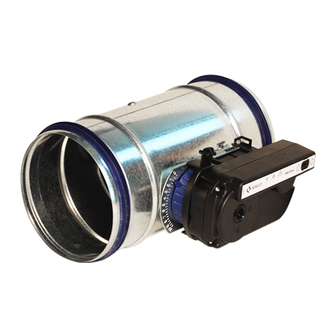
Page 10: Motorised Valves For Vmx System
· 20 % ventilation = 2 minutes with ventilation + 8 minutes without ventilation · 30 % ventilation = 3 minutes with ventilation + 7 minutes without ventilation · etc. With 3 wires, the valves can open simultaneously. TF5814GB_E Aereco S.A. -
Page 11: Assembly
The spurs should be nal flow of 210 m3/h on this valve, add the necessary spurs required to sunk right in, without spaces. block the shutter on position 6 as shown in the diagram below. TF5814GB_E Aereco S.A. -
Page 12: Assembly Of Motorised Valves
Open the shutter fully (shutter on the valve axle) Clip the drive onto the base as per the diagram, then block the drive The valve is assembled, ready to be installed and connected. by turning it clockwise. TF5814GB_E Aereco S.A. -
Page 13: Electrical Connection
> need memorization on the MAIN open closed closed module 6.7. MAINTENANCE The valves do not require any maintenance. Any failures which may occur are reported directly on the main module. TF5814GB_E Aereco S.A. -
Page 14: Airflow Noise Transmitted In The Network By The Valves
Hz in Hz in Hz Valve Ø 42 151 30 108 65 234 45 162 100 360 45 162 85 306 185 666 60 216 120 432 250 900 37 133 100 360 185 666 370 1332 TF5814GB_E Aereco S.A. -
Page 15: Main Module (Main Vmx )
Change of the mode of the VMX Main module · Jumper not present: minimum ventilation reaches 0% ("full or none") N.B. the release jumper can be subsequently repositioned at any moment. A new memorisation of the main module will then be required. TF5814GB_E Aereco S.A. -
Page 16: Assembly
The flashing light indicates the launching of the start-up cycle. The flashing light can perform from one to five cycles. Once the start-up cycle has been completed, you can proceed to configure the system at the main module level. TF5814GB_E Aereco S.A. -
Page 17: Module Configuration
Return to factory configuration (only in the case of malfunction) · turn off the system (circuit breaker) · turn the system back on (circuit breaker) by pressing the memorisation button on the main module until the LEDs start flashing. TF5814GB_E Aereco S.A. -
Page 18: Maintenance
· designed to be mounted on the DIN rail in a power box (width corresponding to four electrical modules) This supply has been validated for EMC. The use of another power supply is under the responsibility of the installer or specifier. Aereco declines any responsibility in case of malfunctioning or damage. MODEL AVE1227 Input Voltage 110 –... -
Page 19: Vmx S-Pre Optical Sensor
4,2 m maxi R = recommended overlap 0,4 m, mini 0 m, maxi 1m. r = recommended detection radius Respect the symmetry of the sensors in relation to the axis of the zone. 2 m, maxi 2,8 m TF5814GB_E Aereco S.A. -
Page 20: Electrical Connection
· modulation of airflow by a motorised valve (multizone) or by acting on the fan speed (unizone). The ventilation flow diminishes every 10 mins in steps of 10% as shown in the graph opposite, returning to 100% when a movement is detec- ted. TF5814GB_E Aereco S.A. -
Page 21: Maintenance
10 mins a maximum of 10% (in order to ventilate the premises sufficiently after all the occupants have left). But where necessary it can increase by n x 10% in the following cycle, according to requirements. 8.9. MAINTENANCE No specific maintenance is required. TF5814GB_E Aereco S.A. -
Page 22: Vmx S-Co2 Co
· power supply and transfer of information via VMX specific bus · the sensor is connected to the system by just 3 wires with a section of 1.5 or 2.5mm² · Maximum number of CO sensors per main module: 1 TF5814GB_E Aereco S.A. -
Page 23: Wiring
4. Install the sensor on the ceiling or on the wall, in a place where the level of CO can be detected in accordance with the instructions for installations detailed before (position). 5. Connect the wires according to the electrical diagram of the system provided in this document. TF5814GB_E Aereco S.A. -
Page 24: Interpretation Of Sensor Signals
Just as for the "full or little" mode, the flow diminishes every 10 mins a maximum of 10% (in order to ventilate the premises sufficiently after all the occu- pants have left). But where necessary it can increase by n x 10% in the following cycle, according to requirements. TF5814GB_E Aereco S.A. -
Page 25: Maintenance
Taking into account the slow circulation speed at the level of sensitive elements, the measurement of CO is not affected by dust or water vapour. The sensor does not require recalibration during its life cycle. It has two infra-red sources with different operating cycles, which enables it to be recalibrated automatically. TF5814GB_E Aereco S.A. -
Page 26: Vmx Relay Out Module
Interpretation of sensor signals BEHAVIOUR OF THE LEDS Default (fast) (x4) Closed (flashes) Open (flashes) (flashes) INTERPRETATION configuration change without new open closed system not configured a module or a sensor is not working correctly memorisation of main module TF5814GB_E Aereco S.A. -
Page 27: Assembly
· connected to the bus by two wires with section 1.5 or 2.5 mm² (flexible or rigid) · maximum number of Relay OUT modules per main module: 2 Relay Terminal: · external communication (lighting up a lamp, etc) TF5814GB_E Aereco S.A. -
Page 28: Vmx Contact In Module
Contact 2 (flashes) Contact 1 (flashes) Contact 1 Contact 2 change of configuration without new a module or a sensor is not Contact 1 open Contact 2 open closed closed configured memorisation of the main module working correctly TF5814GB_E Aereco S.A. -
Page 29: Assembly
· connected to the bus by two wires with section 1.5 or 2.5 mm² (flexible or rigid) · maximum number of Contact IN modules per main module: 2 CTS1, CTS2 Terminal: · receives external information to start up or shut down ventilation immediately. TF5814GB_E Aereco S.A. -
Page 30: Vmx In/Out 0-10 V Module
V => 0 % motion, 10 V => 100 % motion) - Ventilation %: level of ventilation (0-100%) (level of ventilation calculated on the last 10 minutes, 0 V => 0 % ventilation, 10 V => 100 % ventilation TF5814GB_E Aereco S.A. -
Page 31: Assembly
· connected to the bus by two wires with section 1.5 or 2.5 mm² (flexible or rigid) · maximum number of IN OUT 0-10 V modules per main module: 1 IN, OUT Terminal: · external communication (BMS for example) TF5814GB_E Aereco S.A. -
Page 32: Diffusers
Nevertheless, other types of diffusers may be used, providing the diameters are compatible with the network and the flows they offer are compatible with those of the VMX system valves. Where diffusers other than those offered by Aereco are chosen, special attention must be paid to the acoustic performance and air diffusion of the selected product. -
Page 33: Fans
33 / 34 14. FANS Aereco offers different models of fans compatible with the VMX system. Their pressure regulation system, low consumption and flows ranging from 500 to 6,000 m /h make the VCZ and VTZ models particularly suitable. The VCZ model is intended for an interior installation protected from the rain or indoor installation in its outdoor version. The VTZ model is intended for an external installation on the roof. - Page 34 Aereco S.A. 62 rue de Lamirault Collégien 77615 MARNE LA VALLEE CEDEX 3 FRANCE www.aereco.com...
Need help?
Do you have a question about the VMX Series and is the answer not in the manual?
Questions and answers