
Related Manuals for Metallkraft AKM Series


Summary of Contents for Metallkraft AKM Series
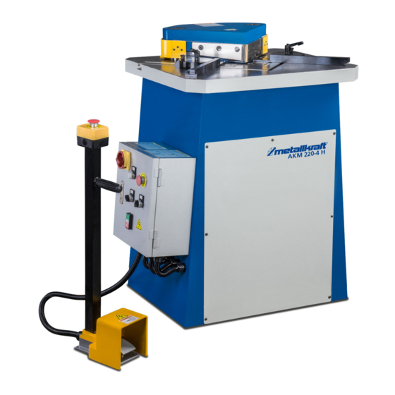
- Page 1 Operating Instructions Hydraulic Notching Machine AKM 220-4 H AKM 220-6 H AKM 220-4 H AKM 220-6 H...
-
Page 2: Table Of Contents
5.1 Delivery and transport ........9 5.2 Packaging............10 Fax: 0049 (0) 951 96555 - 55 5.3 Storage ............. 10 E-Mail: info@metallkraft.de 6 Description of device ..........10 Internet: www.metallkraft.de 6.1 Representation ..........10 6.2 Scope of delivery..........10 6.3 Accessories ............10 7 Setting up...............11... -
Page 3: Introduction
1.3 Limitation of liability You have made a good choice by purchasing the notch- All information and notes in these operating instructions ing machine made by METALLKRAFT. were summarised taking the applicable standards and rules, the state-of-the-art and our long-term knowledge Thoroughly read the operating instructions before commission- and experiences into consideration. -
Page 4: Obligations Of The Operating Company
Safety must implement these in form of operating manuals for the operation of the notching machine. CAUTION! - During the entire lifetime the notching machine, the This combination of symbol and signal words indi- operating company must verify whether the operating cates a possibly dangerous situation which may manuals prepared by her correspond to the current lead to minor or light injuries if they are not avoided... -
Page 5: Personal Protective Equipment
Safety Operator Protective gloves The operator is instructed by the operating company about the assigned tasks and possible risks in case of The protective gloves serve to protect the hands improper behaviour. Any tasks which need to be per- against sharp components as well as against fric- formed beyond the operation in the standard mode tion, abrasions or deep injuries. -
Page 6: Safety Labels On The Machine
Safety 2.6 Safety labels on the machine Safety labels and instructions are attached to the not- ching machine (Fig. 1) which must be observed and followed. Damaged or missing safety symbols on the machine can lead to incorrect actions with personal injury and damage to property. -
Page 7: Intended Use
Intended Use Intended Use Emergency stop button Press the emergency stop button (Fig. 2) located on the The notching machine is designed exclusively for not- control panel and the notching machine will stop imme- ching steel or stainless steel sheets. Notching is done diately. -
Page 8: Technical Data
Technical Data Technical Data Technical Data Model AKM 220-6 H Working table dimensions 650mmx650mm 4.1 Table Notching angle 90° Technical Data Model AKM 220-4 H Strokes 15 1/min Dimensions (LxBxH, max.) 1030x900x1050mm Hubverstellung 6 mm Working pressure 100 bar Cutting capacity 90° 6 mm (400 N/mm²) Motor output... -
Page 9: Transport, Packaging, Storage
Transport, packaging, storage Transport, packaging, storage Transport with a crane: 5.1 Delivery and transport WARNING! Danger to life due to falling load! Delivery Check the notching machine on delivery for any visible If the weight of the notching machine and the per- transportation damage. -
Page 10: Packaging
Description of device Description of device 5.2 Packaging 6.1 Representation All used packaging materials and packaging aids are recyclable and should be taken to a materials recycling Illustrations in these operating instructions are for basic under- depot to be disposed of. standing only and may differ from the actual version. -
Page 11: Setting Up
Setting up Setting up 7.1 Place of installation ATTENTION! Check the load-bearing capacity of the ground before you install the machine. The installation place must be capatable of bearing the weight of the machine and the workpieces. In order to ensure good functioning of the notching ma- chine and a long service life, the installation site should meet the following criteria. -
Page 12: Electrical Connection
Setting up NOTE! After installation, remove the grease from the blank metal parts which has been applied for protection. - Use common solvent for this purpose, e.g. petroleum. - Do not use water, nitro solvents, etc.! After the machine has been thoroughly cleaned, all blank parts must be lightly oiled. - Page 13 Setting up Make sure that Wired grounded devices: - the power connection has the same characteristics This device is factory equipped with a specific electrical (voltage, mains frequency, phase position) as the cable and plug to prevent the device from being motor, connected to an inappropriate circuit for use in an ordi- nary power circuit.
-
Page 14: Settings
Settings Settings Step 3: Loose the bias screws (Pos. 4, Fig. 13) and blade screws (Pos. 5, Fig. 13). Step 4: Measure the tolerance by 0.25 mm thickness ATTENTION! gauge (Pos. 6, Fig. 13). Settings on mechanically acting machine elements Step 5: Adjust the upper and lower blades against to the may only be carried out on the machine by trained thickness gauge. -
Page 15: Changing The Knife
Settings 8.2 Changing the knife Replace the knives in time. Blunt knives lead to poorer cutting performance. Use protective gloves! CAUTION! Use only the recommended original spare blades. There is a risk that poorer material properties will lead to knife breakage and cause injury and dam- age to the machine. - Page 16 Settings When tightening all screws, make sure that there is no gap at the points where the knives are in contact with each other. Replacing the lower knives: NOTE! In order to enable the replacement of the lower knives, first the adjacent upper knife must be dis- mantled! First, perform steps 1 to 8 of the section „Replacing the upper knives“.
-
Page 17: Cutter Bar - Stroke Limit
Settings Fig. 21: Unscrewing of the screws of the lower knife Step 11: Mount the new lower knife. Step 12: Check the cutting gap. If necessary, reset it im- mediately. Step 13: Mount the upper knife back again. Fig. 22: Stroke limit Step 14: Carry out all necessary steps to change the second lower knife as well. - Page 18 Settings Fig. 26: Adjustment elements The clamping lever C (Fig. 26) is used to fix the current set- ting. The measuring tapes embedded in the table are each provided with an outer and inner scale. The outer and inner scales are each inclined by 45° to allow precise adjustment of the stop bars.
-
Page 19: Operation
Operation B: Grid plate, angle wheel DANGER! D: Inner scale Risk of injury!! E: Outer scale There is a risk of injury to the upper limbs (e.g. hands, fingers). ATTENTION! If the setting of the knife position is changed, the ATTENTION! position of the outer stop must be adjusted. -
Page 20: Control Panel
Operation 9.1 Control panel Switches the operating mode mode on or off depend- ing on the switch position. Selector switch for manual/foot operation with signal lamps Activates manual or foot opetating mode depending on switch position. Button for manual upward movement of the cutter bar with signal lamp Moves the upper cutter bar upwards when manual operation is switched on. -
Page 21: Workflow
Maintenance and repair 10 Maintenance and repair 9.4 Workflow Tips and recommendations Tips and recommendations Before starting the production, make a few test cuts! To keep the notching machine in a good operating condition, regular care and maintenance work must be carried out. -
Page 22: Cleaning And Lubricating The Machine
Maintenance and repair 10.2.1 Hydraulic system DANGER! Maintenance and repair work on the hydraulic system When carrying out care, maintenance and repair may only be carried out by specialists with special hy- work, pay attention to protruding parts in order to draulic knowledge. -
Page 23: Lubrication Diagram
Maintenance and repair ATTENTION! - Slowly open the cap of the oil tank to balance the pressure! - Observe the level gauge when filling with oil. Fill the oil only up to the upper mark. - Hydraulic oil is flammable. Do not use an open fire while refilling or replacing hydraulic oil. -
Page 24: Maintenance And Inspection Intervals
Disposal, recycling of used device 10.2.3 Maintenance and inspection intervals Activities to be carried out regularly after initial commissioning: Interval Activity Hydrauc oil weekly check the fill level Hydrauc oil yearly exchange Oil filter yearly clean/change Oil temperature weekly check Hoses lines weekly check... -
Page 25: Disturbances, Possible Causes And Measures.25
If you can not solve the problems with the your notching machine yourself, then please contact your ATTENTION! nearest METALLKRAFT dealer. Please write down following information from the notching machine or If one of the following errors occurs, immediately the operating instructions in advance to help you stop working with the notching machine your problem in the best possible way. -
Page 26: Sparte Parts
Sparte parts 13 Sparte parts 13.1 Ordering spare parts NOTE! The manufacturer warranty shall be rendered void in the event of a use of unauthorised spare parts. DANGER! Risk of injury due to use of incorrect spare parts! The use of incorrect or faulty spare parts may cause risks for operating staff and damage as well as malfunctions. -
Page 27: Spare Parts Drawings
Sparte parts 13.2 Spare parts drawings In case of the service, the following drawings shall help to identify the necessary spare parts. If necessary, send a copy of the parts drawing with the marked components to your dealer. Spare parts drawing AKM 220-4 H AKM-220-4 H Fig. - Page 28 Sparte parts Spare parts drawing AKM 220-6 H AKM-220-6 H Fig. 33: Spare parts drawing AKM 220-6 H AKM-Series 220 | Version 1.07...
-
Page 29: Wiring Diagrams
Wiring diagrams 14 Wiring diagrams 14.1 Electrical circuit diagrams AKM 220-4 H Fig. 34: Electrical circuit diagram AKM 220-4 H AKM 220-6 H Fig. 35: Electrical circuit diagram AKM 220-6 H AKM-Series 220 | Version 1.07... -
Page 30: Hydraulic Circuit Diagram
Wiring diagrams Hydraulic circuit diagram 14.2 Fig. 36: Hydraulic circuit diagram AKM 220-4 H and AKM 220-6 H AKM-Series 220 | Version 1.07... -
Page 31: Ec Declaration Of Conformity
According to Machinery Directive 2006/42/EC, Annex II 1.A Stürmer Maschinen GmbH Manufacturer / distributor: Dr.-Robert-Pfleger-Str. 26 D-96103 Hallstadt hereby declares that the following product Metallkraft® Metal Working Machines Product group: Hydraulic Notching Machine Machine type: AKM 220-4 Designation of the machine:... - Page 32 www.metallkraft.de...
Need help?
Do you have a question about the AKM Series and is the answer not in the manual?
Questions and answers