
Related Manuals for Metallkraft RBM Series


Summary of Contents for Metallkraft RBM Series
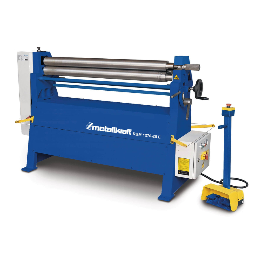
- Page 1 Instruction Manual Plate rolling machines RBM 1050-30 E RBM 1270-25 E RBM 1550-20 E RBM 2050-15 E RBM 1270-25 E...
- Page 2 Imprint Product identification Metallkraft Plate rolling machine Model Item number RBM 1050-30 E 3813201 RBM 1270-25 E 3813202 RBM 1550-20 E 3813203 RBM 2050-15 E 3813204 Manufacturer Stürmer Maschinen GmbH Dr.-Robert-Pfleger-Str. 26 D-96103 Hallstadt Fax: 0049 (0) 951 96555 - 55 E-Mail: info@metallkraft.de...
-
Page 3: Table Of Contents
Contents 1 Introduction .................4 1.1 Copyright....................4 1.2 Customer service .................. 4 1.3 Limitation of liability................4 2 Safety..................5 2.1 Symbol explanation................5 2.2 Responsibility of the operator ............... 6 2.3 Requirements to staff................7 2.4 Personal protective equipment ............. 7 2.5 General safety regulations .............. -
Page 4: Introduction
Introduction Introduction You have made a good choice by purchasing the METALLKRAFT machine. Read the operating manual thoroughly before commissioning the ma- chine. It gives you information about the proper commissioning, intended use and safe and efficient operation and maintenance of your machine. -
Page 5: Safety
Safety In the following cases the manufacturer is not liable for damages: - Non-observance of the operating instructions, - Inappropriate use - Use of untrained staff, - Unauthorized modifications - Technical changes, - Use of not allowed spare parts. The actual scope of delivery may deviate from the explanations and presenta- tions described here in case of special models, when using additional ordering options or due to latest technical modifications. -
Page 6: Responsibility Of The Operator
Safety NOTE! This combination of symbol and signal words indicates a po- tentially dangerous situation which may lead to material or environmental damage if not avoided. Tips and recommendations Tips and recommendations This symbol highlights useful tips and recommenda-tions as well as information for an efficient and trou-ble-free opera- tion. -
Page 7: Requirements To Staff
Safety 2.3 Requirements to staff The different tasks described in this manual represent different requirements to the qualification of the persons entrusted with these tasks. WARNING! Danger in case of insufficient qualification of the staff! Insufficiently qualified persons cannot estimate the risks while using the vacuum cleaner and expose themselves and others to the danger of severe or lethal injuries. -
Page 8: General Safety Regulations
Safety Safety boots Safety boots protect the feet from being crushed, falling parts and slipping over on slippery ground. Protective clothes Protective clothes are made of a tightly fitted fabric without the protruding parts of low tear strength. 2.5 General safety regulations - Use the guards and secure them securely. -
Page 9: Intended Use
Intended Use Intended Use The RBM E plate rolling machine is used exclusively for the production of round shaped parts such as pipes, cones, cylinders, etc. The material to be bent must not exceed the maximum sheet thickness specified for the machine. The machine may only be operated by a single person who has been in- structed in the use and maintenance of the machine. -
Page 10: Technical Data
Technical Data Technical Data RBM 1050-30 E RBM 1270-25 E RBM 1550-20 E RBM 2050-15 E Bending width 1050 mm 1270 mm 1550 mm 2050 mm Max. sheet thickness* 3 mm 2,5 mm 2 mm 1,5 mm Roller Ø 90 mm 90 mm 90 mm 95 mm... -
Page 11: Packaging
Transport, packaging, storage The machine may only be loaded and unloaded by qualified personnel. To avoid accidents, the necessary precautions must be taken when unloading and transporting the machine. DANGER! Before transporting, check that the upper roller lock is in the closed position and that the transport ropes are tightened. -
Page 12: Storage
Description of the machine 5.3 Storage The machine must be thoroughly cleaned before storing it in a dry, clean, dust- and frost-free environment. It must not be shut down with chemicals in a room. If the machine must be stored in a damp room, all electrical components in the control cabinet as well as the hydraulic system must be protected by moisture- absorbing agents. -
Page 13: Optional Equipment
Description of the machine 6.2 Optional equipment - Motor-adjustable / deliverable rear roller - Hardened rollers for stainless steel 6.3 Safety switch For the safety of the operating personnel, the machine is equipped with a safety switch and a safety line. When the leash is operated, the ring shown below is pulled like the EMERGENCY STOP, stopping all machine activities. -
Page 14: Set Up And Connection
Set up and connection Set up and connection 7.1 Set up Requirements for the installation In order to achieve good functionality and long life of the bender, the site should meet the following criteria. site - The substrate must be level, firm and vibration-free. - The installation or working room must be dry and well ventilated. -
Page 15: Danger Zones
Set up and connection Wear protective clothing! Step 1: Check the ground for a horizontal alignment, if necessary, compensate for slight unevenness. Step 2: Attach the round bending machine with ground anchors to the ground and align horizontally with a spirit level. NOTE! After setting up, remove the protective agent from the bare metal parts, which have been applied to protect against... -
Page 16: Assembly Of The Safety Line
Set up and connection Fig. 10: Position of the operator during the bending process (green area) 7.3 Assembly of the safety line DANGER! The safety line is an important safety device and must never be removed during machine operation. Disassembly is only permitted for transport purposes. -
Page 17: Electrical Connection
Set up and connection 7.5 Electrical connection DANGER! Danger to life due to electric current! There is an immediate danger of electrocution on contact with live components. - The machine may only be connected by qualified electrici- ans. - Work on the electrical system should only be carried out by qualified electricians. -
Page 18: Direction Of Rotation Of The Motor
Set up and connection Electrical Box The electric box contains the control elements of the machine and is connected to the pedals. 1 Main switch 2 Start button 3 Stop button 4 Operating display Fig. 13: Electrical box WARNING! The main power supply should be protected by circuit brea- kers against possible overvoltages! DANGER! The electric box may only be opened for maintenance and... -
Page 19: Commissioning
Commissioning Commissioning WARNING! Danger due to insufficient qualification of per- sons! Insufficiently qualified personnel can not assess the risks involved in handling the device and expose themselves and others to the risk of serious or fatal injuries. - All work should only be carried out by qualified persons. - Keep inadequately qualified persons out of the work area. -
Page 20: Operation
Commissioning The material should meet the following requirements: - Dry and clean, free of oil. - The diameter must correspond to the specifications. - The material should have a degree of hardness throughout. - Buying high quality material is advisable - The surface of the areas to be bent should be smooth. - Page 21 Commissioning Standard operation In order to be able to remove a bent workpiece from the machine, the lock of the top roller must be released and the top roller must be removed from the guide. Fig. 14: Release lock of top roller Step 1: Before starting the machine, check the locking of the top roller.
-
Page 22: Bending Operation
Commissioning 8.2 Bending operation Bending may only be performed by qualified personnel experienced in these machines. All steps of bending, pre-bending and conical bending must be car- ried out extremely carefully. It should be noted that a small radius is made by repeating the bending process several times;... - Page 23 Commissioning 8.2.2 Sheet position Bending chart 8.2.3 Pre-bending Pre-bending is the operation whereby the ends of the material are bent to the same radius as the final radius. This will give the best results at full radii (eg making tubes) or for operations where no flat ends are desired. 8.2.4 Bending NOTE! The material hardens after each pass.
- Page 24 Commissioning 8.2.5 Conical bending Conical bending is more difficult than normal bending. The machine perfor- mance is reduced by 30% to 50%, the conical bending capacity decreases by about 25%. The material thickness must be reduced accordingly.. Calculation of the dimension of the workpiece RBM E | Version 1.07...
- Page 25 Commissioning Bending process Step 1: Before conical bending, the sheet must be pre-bent at the ends with parallel rolls. Step 2: Thereafter, the machine must be prepared for conical bending as follows: Move the lower roller and the rear roller to the lowest position. Clutches Conically-bending tool Fig.
- Page 26 Commissioning The above-illustrated hardened bending tool holds the material to be bent co- nically during the bending operation. Fig. 19: Conically bending, drain 8.2.6 Normal bending after conical bending After conical bending, the rollers must be brought back into parallel position. Step 1: Use the handwheels to bring the back roll and bottom roll parallel to the top roll.
- Page 27 Commissioning Step 4: Swing top roller (Fig. 21). Fig. 21: Swing the top roller Step 5: Remove workpiece. Use a crane to support the workpiece. DANGER When the top roller is tilted, the top roller must not be overloaded by the workpiece. The workpiece must be supported by a crane. Step 6: Swing the top roller back into the bearing and lock it with the mechanical lock.
-
Page 28: Maintenance And Cleaning
Maintenance and Cleaning Maintenance and Cleaning Tips and recommendations To ensure that the bending machine is always in good ope- rating condition, regular care and maintenance work must be carried out. WARNING! Danger due to insufficient qualification of per- sons! Insufficiently qualified personnel can not assess the risks involved in maintenance work on the machine and expose themselves and others to the risk of serious injury. - Page 29 Maintenance and Cleaning - Regularly clean the round bending machine. - Treat bare metallic work surfaces with anti-rust spray. - Clean the rollers regularly. The points listed in the table must be lubricated regularly at least once a month or more often for a period of more than eight hours daily. Some of these locati- ons are inside the machine and can only be accessed after removing the cover.
-
Page 30: Troubleshooting
Disposal, recycling of used devices 9.2 Troubleshooting Fault Possible cause Remedy The machine does not work. 1. Defective electrical connection 1. Check the electrical connection. 2. Switch in the OFF position 2. Switch in ON position 3. Contact the service. Engine is running, but the rollers are 1. -
Page 31: Spare Parts
Spare parts 11 Spare parts DANGER! Danger of injury due to use of wrong spare parts! The use of incorrect or faulty replacement parts may cause danger to the operator and cause damage and malfunction. - Only original spare parts from the manufacturer or replace- ment parts approved by the manufacturer must be used. -
Page 32: Spare Parts Drawing
Spare parts 11.2 Spare parts drawing In case of service, the following drawing shall help to identify the necessary spare parts. If necessary, send a copy of the parts drawing with the marked components to your authorized dealer. Fig. 25: Spare parts drawing RBM E | Version 1.07... -
Page 33: Electrical-Schematic
Electrical-schematic 12 Electrical-schematic Fig. 26: Electrical-schematic RBM E | Version 1.07... -
Page 34: Ec Declaration Of Conformity
According to machine directive 2006/42/EC Annex II 1.A Manufacturer/retailer: Stürmer Maschinen GmbH Dr.-Robert-Pfleger-Starße 26 D-96103 Hallstadt herewith declares that the following product ® Product group: Metallkraft Metalworking machines Designation of machine: RBM 1050-30 E RBM 1270-25 E RBM 1550-20 E RBM 2050-15 E Machine type:... -
Page 35: Notes
Notes 14 Notes RBM E | Version 1.07... - Page 36 www.metallkraft.de...
Need help?
Do you have a question about the RBM Series and is the answer not in the manual?
Questions and answers