air avionics AIR Traffic Display 57 Pilot's Manual
Hide thumbs
Also See for AIR Traffic Display 57:
- Pilot's manual (58 pages) ,
- Installation manual (121 pages) ,
- Pilot's manual (56 pages)
Table of Contents

Subscribe to Our Youtube Channel
Related Manuals for air avionics AIR Traffic Display 57


Summary of Contents for air avionics AIR Traffic Display 57
- Page 1 avionics AIR Tra c Display 57 Pilot’s Manual Document: MAN0020A0001 Version: Date: 2018/03/13 Phone: +49 (0) 6224 82 83 87 0 Fax: +49 (0) 6224 82 83 87 7 Internet: http://www.air-avionics.com Mail: support@air-avionics.com...
- Page 2 avionics ATD-57 Pilot’s Manual rev. 2.2 2018/03/13...
- Page 3 Important Please read this manual carefully before using the device. Observe limitations and safety instructions. This manual is an essential portion of the device and must be kept in a safe place. Articles Covered This manual covers the following articles: ATD-57 ‘‘AIR Tra c Display 57’’...
-
Page 4: Table Of Contents
Contents Getting Started Introduction Pilot Controls microSD Card Slot Basic Operation Limitations and Safety Instructions Tra c Display Main Radar View Target Symbology Target Selection Overview Target-Menu Quick Selection Target Out-Of-Range Warning Functions Normal Tra c Warnings Head-On Tra c Warnings Nondirectional tra c warnings Obstacle Warnings Alert Zone Warnings... - Page 5 avionics Contents Software and Database Loading Abnormal Operation Insu cient Data Failures Troubleshooting Con guration Menu Diagram FLARM EULA ATD-57 Pilot’s Manual rev. 2.2 2018/03/13...
- Page 6 avionics Contents ATD-57 Pilot’s Manual rev. 2.2 2018/03/13...
-
Page 7: Getting Started
Getting Started 1.1 Introduction ATD-57 is a Cockpit Display of Tra c information (CDTI) displaying tra c data from connected collision avoidance systems or tra c receivers. Multiple ATD-57 can be used in a single aircraft. The small outline and multifunctional software of the device allow for better system integration in space constrained environments. -
Page 8: Pilot Controls
avionics 1. Getting Started 1.2 Pilot Controls Inner and outer knobs have 16 detents per revolution and can be rotated clockwise and counter-clockwise. The inner knob has a pushbutton. Four softkey-pushbuttons are located on the bezel along the top of the TFT-display. softkey 1 (functi softkey 2 softkey 1 and... - Page 9 avionics 1. Getting Started 1.2.3 Outer Knob Functions On the main radar page, the outer knob changes the display range (zoom). In the menu, the outer knob controls the position of the menu focus. On text input pages the outer knob controls the input position. All functions the outer knob controls are kept in the color green.
-
Page 10: Microsd Card Slot
avionics 1. Getting Started 1.2.5 Discrete Switches Physical toggle-switches can be connected during installation. A switch can be used to suppress all warnings. In one position (switch soruce exercised, GND), all warnings are switched o , in the other position ATD-57 operates normally. A switch can also be used to change the tra c-display orientation from ‘‘track-up’’... -
Page 11: Basic Operation
avionics 1. Getting Started Figure 1.6.: microSD card in correct orientation To remove an inserted microSD Card, use your ngernail to gently push on the card until a click is audible. The card will be released following the click. Use your ngernail to remove the card. -
Page 12: Limitations And Safety Instructions
1.5.1 Liability IN NO EVENT WILL AIR AVIONICS BE LIABLE FOR ANY INCIDENTAL, SPECIAL, INDIRECT OR CONSEQUENTIAL DAMAGES, WHETHER RESULTING FROM THE USE, MISUSE OR INABILITY TO USE THE PRODUCT OR FROM DEFECTS IN THE PRODUCT. -
Page 13: Tra C Display
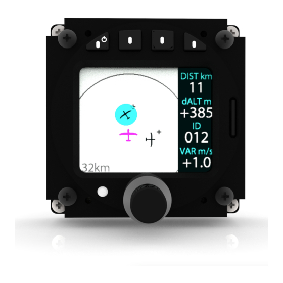
Tra c Display 2.1 Main Radar View ATD-57 displays tra c data from connected tra c systems on a radar-like view. Tra c- targets are shown as aircraft symbols. The own ship-position is shown as a magenta aircraft symbol. A circle depicts the current display range (also shown numerically in the lower left hand corner of the screen). - Page 14 avionics 2. Tra c Display Figure 2.3.: Symbol for circling aircraft (e.g. glider). 2.2.2 Target Relative Altitude A small indicator on the right side of target symbols shows the targets relative altitude. A ‘‘+’’ shows that the target is above the own ship, a ‘‘–’’ below. Figure 2.4.: Aircraft below (little minus-sign) and above (little plus-sign) the own ships current altitude.
- Page 15 avionics 2. Tra c Display 2.2.3 Target Heading Target symbols always resemble the targets current heading if available. The nose of the target symbol always shows into the direction the target is heading towards. In some cases, no target heading is available, for example if the target is not received continuously or if the target’s FLARM system and/or the own ship’s FLARM sytem is con gured to STEALTH mode If no target heading is available, a diamond-shaped symbol is shown.
-
Page 16: Target Selection
Target Selection 3.1 Overview If target selection is activated, targets can be selected using the inner knob . The selected target is highlighted in cyan color. To change the selection, rotate the inner knob . DIST km dALT m +222 VAR m/s -1.2 Figure 3.1.: Main radar view with active target selection. - Page 17 avionics 3. Target Selection Name AEC Walldorf Freq 118.275 Regis.. D-KCCW Type S. Dimona Home EDGX Set Color Figure 3.2.: Target-Menu For targets with FLARMNet database information available, the target menu contains detailed FLARMNet information. If no database information is available for the target, only basic data is shown in the target menu.
-
Page 18: Quick Selection
avionics 3. Target Selection ID (Target Tra c Address) NAME (Target Owner Name) CALL (Target Call- sign) REG (Target Tail Number) Target Menu (For TYPE (Target Air- selected target, Main Radar View craft Type) short push to en- ter) HOME (Target Home Airport) FREQ (Target COM Frequency) - Page 19 avionics 3. Target Selection DIST km DIST km DIST km DIST km dALT m dALT m dALT m dALT m +222 +222 +222 VAR m/s VAR m/s VAR m/s VAR m/s -1.2 -1.2 -0.2 -1.2 Figure 3.5.: Quick selection process: Radar Screen, busy tra c situation push any softkey to open quick selection menu push softkey for quick selection of target...
-
Page 20: Target Out-Of-Range
avionics 3. Target Selection DIST km dALT m +222 VAR m/s -0.2 Figure 3.6.: Target assignation to quick select list. The Target can be assigned to the third position (little ‘‘+’’-sign) Deletion To delete a target from the quick select list, perform the following steps. Select the desired target on the radar view or via quick selection. - Page 21 avionics 3. Target Selection The circle increases in size around the last known position of the target. The size increases with the maximum possible speed the formerly received target can y (depends on target type). If the circle reaches the edge of the radar screen, it is displayed along the edge.
-
Page 22: Warning Functions
Warning Functions ator 1232 Relative altitude of selected ta While ATD-57 is capable of displaying warning messages, it does not computate threat- 12:32:02 Climbrate of selected target or warning-levels. Warning messages are always triggered by connected systems. Familiarization with limitations of connected systems is essential and recommended before using ATD-57. -
Page 23: Head-On Tra C Warnings
avionics 4. Warning Functions 90° 90° 90° 0.8km Figure 4.2.: Normal Tra c Warning Screen The horizon style indicator does not provide for attiude reference of the own ship 4.2 Head-On Tra c Warnings Con icting head-on tra c is displayed using a ‘‘horizon-Style’’ indication depicting the con icting target in a head-on symbology. -
Page 24: Obstacle Warnings
avionics 4. Warning Functions Figure 4.4.: Warning from nondirectional target (ring-indicator in amber, same altitude) 4.4 Obstacle Warnings ATD-57 is capable of displaying obstacle warnings, for example from a FLARM-Compatible device with obstacle database. Obstacles are not shown on the radar screen. Please consult the documentation of the connected system for details about obstacle warnings. - Page 25 avionics 4. Warning Functions Alert zones are displayed in low contrast grey color to minimize interference with other display content on the radar view. DIST km dALT m +222 VAR m/s -0.2 Figure 4.6.: Cylindrical alert zone with reference point and border (dropzone). In some cases, an alert zone may not be visible on the radar view, for example because the display range is too low (zoom level too high), and the alert zone is too large.
-
Page 26: Suppressing Warnings
avionics 4. Warning Functions DIST km dALT m +222 VAR m/s -0.2 Figure 4.8.: Alert zone warning screen with zone visible on the radar view, own ship outside the alert zone. Beam points into the direction of the alert zone reference point. 4.6 Suppressing Warnings Warning messages (aural annunciation and warning display) can be suppressed for a time of two minutes by pushing twice (doubleclicking) on the inner knob pushbutton . -
Page 27: System Con Guration
System Con guration 5.1 Con guration Operations 5.1.1 Con guration Menu ATD-57 is con gured in the con guration menu. To enter the con guration menu, push the inner knob pushbutton for at least 2 seconds (long push). The menu contains several con guration options and informations about ATD-57 and connected systems. - Page 28 avionics 5. System Con guration 4. Push the inner knob pushbutton to execute your selection. 5. Push the ESC softkey to leave the menu. 5.2.2 HMI Illumination Brightness Control Human machine interface (HMI) illumination brightness (screen and buttons) can be controlled using independent methods, only one brightness control method can be used at a time.
- Page 29 avionics 5. System Con guration Now the brightness level is adjusted using the ambient light sensor in the front bezel of the device. Restrictions to minimum and maximum brightness levels are con gured in MINIMUM and MAXIMUM. Brightness Control over Aircraft Lighting Bus In order to use the aircraft lighting bus, the following con guration actions have to be taken: 1.
- Page 30 avionics 5. System Con guration 6. set the aircraft lighting bus to the maximum level using the lighting bus control in your aircraft. 7. Push the inner knob pushbutton to execute your selection. 8. Push the ESC softkey to leave the menu. 5.2.3 Power On Mode ‘‘Power On Mode’’...
-
Page 31: View Con Guration
avionics 5. System Con guration The NO WARNINGS and ORIENTATION functions can be individually mapped to input 1 (on the upper connector) and input 2 (on the lower connector). To change the switch con guration, please carry out the following steps: 1. - Page 32 avionics 5. System Con guration DIST km dALT m +222 VAR m/s -1.2 Figure 5.1.: Dark Style switched on To activate ‘‘Dark Style’’ , please carry out the following steps: 1. Open the menu with a long push on the inner knob pushbutton . 2.
- Page 33 avionics 5. System Con guration 5.3.5 Target Select If target selection is activated, targets can be selected using the inner knob . The selected target is highlighted in cyan color. Additional information about the selected target is shown on the right hand side of the radar view. If target selection is not active, the radar screen is larger and no additional information is shown.
-
Page 34: Tra C System Con Guration
avionics 5. System Con guration 4. Push the ESC softkey to leave the menu. 5.4 Tra c System Con guration In the con guration menu, TRAFFIC SYSTEM holds con guration parameters for the con- nected tra c system. INFO contains information about the connected tra c system. SETTINGS allows for con guration of the connected tra c system. -
Page 35: Software And Database Updates
Software and Database Updates 6.1 Version Identi cation Software version can be reviewed in CONFIGURATION MENU INFO. For details on databases currently available, navigate to CONFIGURATION MENU INFO DATABASES. 6.2 Software and Database Loading Software upgrades and databases are loaded using the integrated microSD card slot and a microSD memory card. - Page 36 avionics 6. Software and Database Updates To insert a microSD card, insert the card into the slot, print facing to the display, little nose facing upwards and gently push the card until it clicks in. Inserting the microSD card in the wrong orientation may damage the slot. Figure 6.2.: microSD card in correct orientation To remove an inserted microSD card, use your ngernail to gently push on the card until a click is audible.
- Page 37 avionics 6. Software and Database Updates A stable power supply is required for bootloader updates. Never disconnect power during the process. This might damage the device beyond repair. 1. Ensure software version 1.3 is installed. Update any earlier versions to 1.3. 2.
-
Page 38: Abnormal Operation
Abnormal Operation 7.1 Insu cient Data ATD-57 requires a set of data from a connected tra c systems to work properly. ATD-57 continuously seeks to nd data on its data interfaces. It automatically switches data-transfer- rates and con guration until it receives data. Position Data (e.g. - Page 39 avionics 7. Abnormal Operation Figure 7.2.: ATD-57 does not know the position. ‘‘NO GPS’’ message instead of own ship symbol is shown. Nondirectional ring-indicator is shown. 7.1.3 No Heading Data ATD-57 computes the current heading of the own ship from position data. In order to compute a heading, the own ship has to move.
-
Page 40: Failures
avionics 7. Abnormal Operation 7.2 Failures ATD-57 features a range of built-in self test features that continuously monitor its system state and the state of connected tra c systems to detect failures. The detection of a failure is always annunciated to ightcrew on the display. Depending on detected failure and failure severity, the system may seize to function or functionality may be limited. -
Page 41: Troubleshooting
Troubleshooting 8.0.1 My unit always shows a message ‘‘waiting for tra c.. ’ ’ In this case, no data from a tra c system is received by ATD-57. 1. Check if wiring is correct and as intended 2. Check if con guration of connected tra c system is correct and compatible to ATD-57 3. - Page 42 avionics 8. Troubleshooting 1. Please update the device software to the latest version. Any version newer than 1.0 will resolve the issue. 2. If an update is not possible for the moment, please go to menu > installation > illumination and set illumination mode to ‘‘AUTO’’ . After this, the unit will work normally with microSD card inserted.
-
Page 43: Con Guration Menu Diagram
Con guration Menu Diagram For better readability, the menu diagram is split into multiple separate parts on di erent pages of this manual. Alert sounder vol- ume con guration SOUNDER VOL- page: Values from 0 (quiet) to 5 (full loud). Default: 3 PID: Product iden- ti cation VID: Vendor iden-... - Page 44 avionics A. Con guration Menu Diagram MODE. Parameters MANUAL, AUTO, or LIGHTINGBUS. Default: MANUAL Illumination inten- sity con guration page for man- MANUAL INTEN- ual mode: Values SITY from 0 (dark) to 100 (full bright). Default: 80 Global minimum allowed illumina- tion intensity: Val- MINIMUM ues from 0 (dark)
- Page 45 avionics A. Con guration Menu Diagram POSITION IDENTI- FIER 1 POSITION IDENTI- FIER 2 QUICK SELECT POSITION IDENTI- FIER 3 POSITION IDENTI- FIER 4 KM: Kilometers (default) DISTANCE NM: Nautical Miles SM: Statute Miles M: Meters (de- Con guration fault) TRAFFIC VIEW ALTITUDE Menu...
- Page 46 avionics A. Con guration Menu Diagram STATUS: Status of connected tra c system DEVTYPE: Device type of connected tra c system SWVER: Software version of con- nected tra c sys- SER: Serial num- ber of connected tra c system INFO REGION: Usable re- gion of connected tra c system...
- Page 47 avionics A. Con guration Menu Diagram PILOT: Pilot’s name COPIL: Copilot’s name REG: Aircraft regis- tration TYPE: Aircraft type FLIGHT RECORDER COMPID: Competi- tion ID CLASS: Competi- tion class LOG INT: Logging interval STEALTH: Activates FLARM stealth TRAFFIC SYSTEM mode PRIVACY No Track: Acti- vates FLARM No-...
-
Page 48: Flarm Eula
FLARM EULA This appendix contains the End User License Agreement issued by FLARM Technology Ltd., the licensor of FLARM devices. By purchasing or using a FLARM device or by downloading, installing, copying, accessing, or using any FLARM Technology Ltd. (hereafter ‘‘FLARM Technology’’) software, rmware, license key, or data, you agree to the following terms and conditions. - Page 49 avionics B. FLARM EULA 2.2. FLARM must be installed according to the Installation Instructions and the EASA Minor Change Approval, or the national equivalent. 2.3. FLARM cannot warn in all situations. In particular warnings may be incorrect, late, missing, not being issued at all, show other threats than the most dangerous or distract the pilot’s attention.
- Page 50 avionics B. FLARM EULA 3. Intellectual Property No part of the software, rmware, license keys, data (including obstacle databases), the FLARM radio protocol and messages, and the FLARM hardware and design may be copied, altered, reverse engineered, decompiled or disassembled without an explicit and written approval by FLARM Technology.
- Page 51 avionics B. FLARM EULA 6.2. Limitation of Liability. In no event shall FLARM Technology be liable to you or any party related to you for any indirect, incidental, consequential, special, exemplary, or punitive damages (including, without limitation, damages for loss of business pro ts, business interruption, loss of business information, loss of data or other such pecuniary loss), whether under a theory of contract, warranty, tort (including negligence), products liability, or otherwise, even if FLARM Technology has been advised of the possibility of such damages.
- Page 52 avionics B. FLARM EULA waiver by that party as to subsequent enforcement of rights or subsequent actions in the event of future breaches. 7.5. Amendments. FLARM Technology reserves the right, in its sole discretion, to amend this Agreement from time to time by posting an updated version of the Agreement on www.
Need help?
Do you have a question about the AIR Traffic Display 57 and is the answer not in the manual?
Questions and answers