air avionics AIR Control Display 57 Installation Manual
Hide thumbs
Also See for AIR Control Display 57:
- Pilot's manual (58 pages) ,
- Pilot's manual (52 pages) ,
- Pilot's manual (56 pages)
Table of Contents

Subscribe to Our Youtube Channel
Related Manuals for air avionics AIR Control Display 57


Summary of Contents for air avionics AIR Control Display 57
- Page 1 AIR Control Display 57 Installation Manual Document: MAN0010A0002 Version: Date: 2018/03/29 Phone: +49 (0) 6224 82 83 87 0 Fax: +49 (0) 6224 82 83 87 7 Internet: http://www.air-avionics.com Mail: support@air-avionics.com...
- Page 2 avionics ACD-57 Installation Manual rev. 2.0 2018/03/29...
- Page 3 Observe limitations and safety instructions. This manual is an essential portion of the device and must be kept in a safe place. Articles Covered This manual covers the following articles: ACD-57 ‘‘AIR Control Display 57’’ Revision History Rev. Date Status...
- Page 4 avionics Product Support If you have questions, our product support team will be happy to help you. Contact us via support@air-avionics.com or by phone. Please nd details about our hotlines and availability online at http://www.air-avionics.com ACD-57 Installation Manual rev. 2.0 2018/03/29...
-
Page 5: Table Of Contents
Contents General Description Introduction Equipment Description System Capabilities Technical Speci cations Regulatory Compliance Liability Unpacking and Inspecting Equipment Installation Materials System Interconnects and Interfaces Pin Function List Data Interfaces Power and Lighting Functions Altitude Functions Installation Overview General Handling Recommendations Workmanship Cabling and Wiring Considerations Pressure Tubing Considerations... - Page 6 avionics Contents Wiring Checks Connector Engagement Checks System Con guration Con guration Operations License Management Device Con guration Altimeter Con guration ACD-57 COM Control Con guration Connected COM System Con guration ACD-57 XPDR Control Con guration Connected XPDR System Con guration Ground Checks Interface Checkout Serial Control Interface Check...
- Page 7 avionics Contents Cabling and Con guration Examples Wiring Diagrams Generic Wiring Diagram COM Wiring Diagrams Transponder Wiring Diagrams COM and Transponder Wiring Diagrams Serial Control Interface RS-232 Interface Message Structure Multiple Device Support Con guration Sentences Command Sentences Status Sentences Error Sentences Checkout Log Installation...
- Page 8 avionics Contents ACD-57 Installation Manual rev. 2.0 2018/03/29...
-
Page 9: General Description
This manual is intended to provide mechanical and electrical information for use in the planning and design of an installation of the Air Control Display 57 (ACD-57) into an aircraft. This manual is not a substitute for an approved airframe-speci c maintenance manual, installation design drawing, or complete installation data package. -
Page 10: System Capabilities
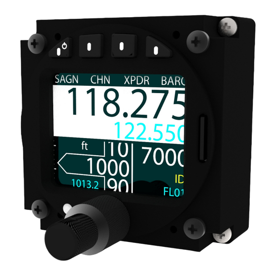
1. General Description Figure 1.1.: Isometric view of AIR Control Display 57 1.3 System Capabilities ACD-57 is a small multi-function control display intended for controlling Mode-S Transpon- ders (ATC radar beacon system, ATCRBS) and Aircraft Radios (Airborne VHF Transceivers). - Page 11 avionics 1. General Description Please nd a dimensional drawing in appendix B 1.4.2 Environmental Speci cations The ETSO approval is only valid if the device is installed within an environment matching the quali cation environment. The ACD-57 has been tested in accordance with RTCA DO-160D Chg.
-
Page 12: Regulatory Compliance
avionics 1. General Description 1.4.3 Housing and Human Machine Interface ACD-57 has an all-metal housing with anti-re ective blackout nish on all parts visible to the ight crew. ACD-57 is controlled by two concentric rotary knobs (not illuminated) and four softkey pushbuttons (illuminated). - Page 13 avionics 1. General Description 2. ETSO-C10b#9, Using SAE AS8009B instead of AS392C. 3. ETSO-C10b#10, Do not display ALTITUDE or ALT next to the tape style indicator. 4. ETSO-C88a#1, Using ED-26 instead of SAE AS8003. 5. ETSO-C113#1, Using SAE AS8034A instead of AS8034. 1.5.3 Non-ETSO Functions Non-ETSO functions provided by the ACD-57 are: Control of a VHF COM (e.g.
-
Page 14: Liability
1.6 Liability IN NO EVENT WILL AIR AVIONICS BE LIABLE FOR ANY INCIDENTAL, SPECIAL, INDIRECT OR CONSEQUENTIAL DAMAGES, WHETHER RESULTING FROM THE USE, MISUSE OR INABILITY TO USE THE PRODUCT OR FROM DEFECTS IN THE PRODUCT. -
Page 15: Installation Materials
1. General Description Should there be missing parts or spare parts required, please contact AIR Avionics or visit http://www.air- store.eu 1.8 Installation Materials 1.8.1 Tools required but not supplied Standard Tools Tool Speci cation Description Phillips screwdriver PH 0... - Page 16 avionics 1. General Description 1.8.3 Optional Standard Kit Accessories Part number Description B443 D-SUB15HD connection kit with receptacle, backshell, crimp terminals, and wire B394 AIR Control Display to RJ45 Cable (FLARM/IGC Standard) B427 AIR data bus Cable (D-SUB 15HD) - 1m B428 AIR data bus Cable (D-SUB 15HD) - 3m B429...
-
Page 17: System Interconnects And Interfaces
System Interconnects and Interfaces Connector 1 Connector 2 Figure 2.1.: System interconnects overview. View from the back. Both connectors are D-SUB 15 high density male types. Small pin numbers are molded into the connectors for easier pin identi cation. Pin numbers of mating (female) connectors are identical, therefore mating pins have identical numbers. -
Page 18: Pin Function List
2.2 Data Interfaces 2.2.1 Bus Data Interface ACD-57 uses a data bus interface to connect to other AIR Avionics devices such as other ACD-57 units, aircraft radio, or air tra c control radar beacon devices (XPDR). ACD-57 Installation Manual rev. 2.0 2018/03/29... - Page 19 2. System Interconnects and Interfaces Only AIR Avionics articles intended for use with ACD-57 may be connected to the data bus. Pin Name Pin number CAN Hi 1.8/2.8 In/Out CAN Lo 1.7/2.7 In/Out CANTERM 1.12/2.12 In/Out Participating systems on a data bus are frequently referred to as ‘‘nodes’’ .
- Page 20 ACD-57 sends and receives data in the CANaerospace protocol. For a detailed description Reserved of supported datasets, please contact AIR Avionics support. Lighting Bus Input 1 (ILLUMIN1) 2.2.2 Serial Data Interface ACD-57 is capable of interfacing with other aviation instruments by sending and/or receiving serial data on its serial ports.
-
Page 21: Power And Lighting Functions
avionics 2. System Interconnects and Interfaces The table below contains maximum recommended cable lengths using shielded data cables for an RS-232 data interface. Exceeding these cable lengths may reduce signal integrity and therefore the reliability of the data interface. Data Rate Recommended Cable Length (meter) Comment 4800 Bd... -
Page 22: Altitude Functions
avionics 2. System Interconnects and Interfaces For reasons of simplicity, some wiring diagrams in this manual only show one power input in use. For redundancy it is however strongly recommended to connect independent power sources to power inputs on each of the two connectors (one source per connector). - Page 23 avionics 2. System Interconnects and Interfaces Figure 2.6.: Pressure Connector ACD-57 Installation Manual rev. 2.0 2018/03/29...
-
Page 24: Installation Overview
Installation Overview 3.1 General Handling Recommendations 3.1.1 ESD Handling Recommendations To avoid damage to ACD-57, take precautions to prevent Electrostatic Discharge (ESD) when handling the unit, connectors, and associated wiring. ESD damage can be prevented by touching an object that is of the same electrical potential as the unit before handling the unit itself. -
Page 25: Cabling And Wiring Considerations
avionics 3. Installation Overview Pictorial Reference On http://workmanship.nasa.gov a pictorial reference ‘‘intended to provide insight to certi ed operators, inspectors and instructors who visually assess the compliance of ight hardware to locally applicable requirements’’ is available. 3.3 Cabling and Wiring Considerations 3.3.1 General Wiring Considerations Wiring should be installed in accordance with applicable regulations. -
Page 26: Pressure Tubing Considerations
avionics 3. Installation Overview If data bus wiring requirements are not met, equipment performance may be compromised 3.4 Pressure Tubing Considerations Pressure tubing should be installed in accordance with applicable regulations. Route the tubing as appropriate. Avoid sharp bends. Make sure the aircraft static pressure port is plumbed directly to the unit static pressure input port. - Page 27 3. Installation Overview Device Make Interface Required License Tested SW Version AIR COM AIR Avionics Data bus none required – AR 6201 AR6201-(022) Becker RS-422 via RS-232 Becker Interface CM: 4.06, CH: 2.06 RT 6201 RT6201-(020) Becker RS-422 via RS-232 Becker Interface 1.51...
-
Page 28: Air Circulation And Cooling
The following transponders have been tested to be compatible to ACD-57: Device Part Number Make Interface Required Function License Tested SW Version VT-01 VT-0102 AIR AVIONICS Data bus No license required 1.60 and newer VT-01 VT-0104 AIR AVIONICS Data bus No license required 1.60 and newer... -
Page 29: Compass Safe Distance
avionics 3. Installation Overview Units tightly installed heat each other through radiation, convection, and sometimes by direct conduction. Even a single unit operates at a much higher temperature in still air than in moving air. Fans or some other means of moving the air around electronic equipment are usually a worthwhile investment. -
Page 30: Installation Procedures
Installation Procedures We recommend installing ACD-57 according to the following process: 1. Equipment mounting 2. Wiring: Manufacturing and testing of wiring harness or selection of standard accessories 3. Wiring harness and interconnect installation 4. Post installation con guration, checkout, and documentation 4.1 Equipment Mounting 1. -
Page 31: Post Installation Con Guration, Checkout, And Documentation
avionics 4. Installation Procedures 4.4 Post Installation Con guration, Checkout, and Documentation A summary of the steps required for checkout, con guration, and installation documentation is as follows: Perform the installation checks. Instructions can be found in chapter 5. Con gure the unit for the speci c installation. Work though every con guration item according to instructions in chapter 6. -
Page 32: Post Installation Checkout
Post Installation Checkout This chapter contains instructions for checking out an ACD-57 installation. Checks shall ensure the system is properly installed and functioning correctly. 5.1 Wiring Checks Verify that all cables are properly secured. Check the movement of aircraft controls to verify there is no interference between the cabling and controls. -
Page 33: System Con Guration
System Con guration 6.1 Con guration Operations 6.1.1 Con guration Menu ACD-57 is con gured in the con guration menu. To enter the con guration menu, push the inner knob pushbutton for at least 2 seconds (long push). The menu contains several con guration options and informations about ACD-57 and connected systems. -
Page 34: License Management
If none of the above mentioned functions are to be used, no license has to be installed. In this case, skip this section. 6.2.2 Purchasing Function Licenses Function licenses can exclusively be purchased online in the AIR Avionics License Store. Please visit http://www.air-store.eu for details. 6.2.3 Function License Installation To install a license, please carry out the following steps: 1. -
Page 35: Device Con Guration
avionics 6. System Con guration 3. Enter a valid license installation code: Use the inner knob to select a character. Use the outer knob to select a digit. 4. Push the inner knob pushbutton to execute your selection. 5. After the license installation code has been successfully validated, the license is installed. - Page 36 avionics 6. System Con guration DONE DONE RESET ILLUMINATION MODE ILLUMINATION OVERRIDE AUTO FAST +/- OVERRIDE OVERRIDE ACTIVE Figure 6.1.: Illumination override page. On the left the automatic illumination con guration is active, current illumination mode is shown. On the right the override is active. 6.3.4 Alert Sounder Volume ACD-57 features an integrated alert sounder (buzzer) for failure and warning annunciation.
- Page 37 avionics 6. System Con guration Manual Brightness Control To change the HMI illumination mode to manual brightness control, please carry out the following steps: 1. Open the menu with a long push on the inner knob pushbutton . 2. Use the inner knob to navigate to DEVICE INSTALLATION ILLUMINATION MODE.
- Page 38 avionics 6. System Con guration 5. Push the ESC softkey to leave the menu. To con gure the correct input pin for the lighting bus, please carry out the following steps: 1. Open the menu with a long push on the inner knob pushbutton . 2.
- Page 39 avionics 6. System Con guration 6.3.7 Data Ports GPS Source ACD-57 has two independent RS-232 data ports and a CAN data bus interface. Both RS-232 data ports can be used to accept data from an RS-232 NMEA GPS source, and the CAN data bus can accept GPS information e.g.
- Page 40 avionics 6. System Con guration The value range from 100 to 109 is reserved for ACD-57 in a data bus installation. The default node id entered in the factory is 100. It is recommended to enter the folowing IDs in multi-ACD-57 installations: rst ACD-57: Node ID 100 (factory default) second ACD-57: Node ID 101 third ACD-57: Node ID 102...
- Page 41 avionics 6. System Con guration 3. Use the inner knob to select a value: AUTO (for automatic data rate selection), or one of the other values for a xed data rate. 4. Push the inner knob pushbutton to execute your selection. 5.
-
Page 42: Altimeter Con Guration
avionics 6. System Con guration 6.4 Altimeter Con guration The ALTIMETER menu section contains speci c con guration parameters for the integrated altimeter. 6.4.1 Units Units for altitude and pressure are user con gurable. Altitude units con gurable to meters or feet Pressure units con gurable to hectopascals (millibars) or inches of mercury The default settings are meters and hectopascals. - Page 43 avionics 6. System Con guration 1. Open the menu with a long push on the inner knob pushbutton . 2. Use the inner knob to navigate to ALTIMETER INSTALLATION BARO SOURCE. 3. Use the inner knob to select a source: NOT CONNECTED, STATIC PORT (uses static port), or DATA BUS (uses altitude from other source on the data bus).
-
Page 44: Com Control Con Guration
avionics 6. System Con guration 6.5 ACD-57 COM Control Con guration The COM CONTROL menu section contains setup parameters for the control of a connected COM system. 6.5.1 Channel Spacing The current channel spacing used in the ACD-57 can be selected in this parameter. It can be set to both, 25kHz, or 8.33kHz. - Page 45 avionics 6. System Con guration SAGN XPDR SAGN XPDR 118.275 118.275 WALLDORF INFO 122.550 122.550 7000 7000 FL222 FL222 SAGN NRST HIST SAGN NRST HIST 118.275 118.275 WALLDORF INFO 129.970 129.970 MALSCH GLD Figure 6.2.: COM main page with STATION NAMES parameter set to ON on the left and to OFF on the right.
- Page 46 avionics 6. System Con guration SAGN NRST HIST SAGN NRST HIST 118.275 118.275 WALLDORF INFO WALLDORF INFO 129.970 129.970 MALSCH GLD MALSCH GLD Figure 6.3.: COM main page with KNOB USE parameter set to VOLUME on the left and to CHANNEL on the right.
- Page 47 avionics 6. System Con guration 2. Use the inner knob to navigate to COM CONTROL INSTALLATION COM TYPE. 3. Use the inner knob to to select a desired type (AIR COM, BECKER or KRT2). 4. Push the inner knob pushbutton to execute your selection. 5.
-
Page 48: Connected Com System Con Guration
avionics 6. System Con guration 6.6 Connected COM System Con guration The COM SYSTEM section contains setup parameters for a connected VHF transceiver. Depending on the type of connected VHF transceiver, di erent parameters are available. Where possible, menu parameter names are consistent to parameter names in the VHF transceiver’s documentation. -
Page 49: Xpdr Control Con Guration
avionics 6. System Con guration 6.7 ACD-57 XPDR Control Con guration The XPDR CONTROL section contains setup parameters for the control of a connected XPDR system. 6.7.1 VFR Preset Here a preset value for the VFR squawk code can be entered. This value is used when the VFR Softkey is pressed on the XPDR page. - Page 50 avionics 6. System Con guration 4. Push the ESC softkey to leave the menu. 6.7.3 XPDR Type In XPDR TYPE the type of the controlled transponder unit is selected. Currently only the AIR Avionics VT01 is supported. The default setting for this parameter is VT01. To change transponder type con guration, please carry out the following steps: 1.
-
Page 51: Connected Xpdr System Con Guration
avionics 6. System Con guration 6.8 Connected XPDR System Con guration The XPDR SYSTEM section contains setup parameters for a connected XPDR system. Please consult the XPDR system’s documentation for details on parameters and recommended values. Note that for the VT-01, the system state, software versions, and con guration is not known to the ACD-57 unless the VT-01 has been set to ALT mode at least once during the runtime of the ACD-57. - Page 52 avionics 6. System Con guration 4. Push the inner knob pushbutton to execute your selection. 5. Push the ESC softkey to leave the menu. Maximum Speed Category In this menu, the maximum speed category of the aircraft shall be entered. The default value is 0.
- Page 53 avionics 6. System Con guration 4. Push the inner knob pushbutton to execute your selection. 5. Push the ESC softkey to leave the menu. ADS-B L/W code In this menu, the ADS-B length/width code shall be entered. The default value is 0. To enter an L/W code, please carry out the following steps: 1.
- Page 54 avionics 6. System Con guration XPDR System Altitude Source Here the altitude data source for a connected XPDR system can be selected to either be RS-232 or data bus. The default value for this parameter is DATA BUS. For VT-01 Mode-S transponders, the parameter has to be set to DATA BUS. To change the altitude source of a connected XPDR system, please carry out the following steps: 1.
-
Page 55: Ground Checks
Ground Checks 7.1 Interface Checkout 7.1.1 Data Bus Checks In order to test data bus integrity and bus load, a pragmatic function test of ACD-57 connected to a second bus node can be performed. The second node may be another ACD-57 or any other compatible device, for example an aircraft radio or radar beacon system. -
Page 56: Altimeter Check
avionics 7. Ground Checks 7.5 Altimeter Check For altimeter checkout, use only aircraft manufacturer approved checkout procedures. 7.6 Lighting and Controls Check 7.6.1 Lighting Bus Check The display and bezel key backlight on ACD-57 can track an external lighting bus input and use it to vary the display and bezel key illumination levels accordingly. -
Page 57: Version / Revision Check
avionics 7. Ground Checks 1. Ensure that ILLUMINATION is set to AUTO. 2. Cover the light sensor with your nger and see if display and bezel illumination changes within a time of some seconds. 7.6.3 Controls check This check veri es that all controls operate correctly. 1. -
Page 58: Con Guration And Checkout Documentation
Con guration and Checkout Documentation 8.1 Con guration Documentation It is mandatory for each con guration that the con guration is logged in a document that is to be added to the aircraft records. A con guration log form is provided in appendix H 8.2 Checkout Documentation It is mandatory for each installation that the checkout is logged in a document that is to be added to the aircraft records. -
Page 59: Maintenance
Maintenance 9.1 Software and Database Loading Software upgrades and station databases are loaded using the integrated microSD card slot and a microSD memory card. While the software is actually loaded onto the device, the station database remains on the microSD card. Therefore database information is only accessible if the microSD card is installed. - Page 60 9.1.2 Using a Station Database To use a database, please carry out the following steps: 1. Purchase a valid station database le in the AIR Avionics License Store. Please visit http://www.air-avionics.com/license for details. 2. Load the station database le onto a microSD card.
-
Page 61: Cleaning
avionics 9. Maintenance holding the station database le is inserted. If the microSD card is removed, the database and all related functions are unavailable. 9.1.3 Loading Software to ACD-57 In order to perform a software update, please carry out the following steps: 1. -
Page 62: Bibliography
Bibliography [1] AIR Avionics, ACD-57: Pilot’s Manual, March 2018. ACD-57 Installation Manual rev. 2.0 2018/03/29... -
Page 63: Assembly And Installation Drawings
Assembly And Installation Drawings Figure B.1.: Dimensional drawing, all dimensions in millimeters ACD-57 Installation Manual rev. 2.0 2018/03/29... -
Page 64: Con Guration Menu Diagram
Con guration Menu Diagram DEVICE ALTIMETER COM CONTROL COM SYSTEM Con guration XPDR CONTROL Menu XPDR SYSTEM FAILURES PIN CODE LICENSES For better readability, the menu diagram is split into multiple separate parts on di erent pages of this manual. This diagram shows the con guration menu levels required for installation. - Page 65 avionics C. Con guration Menu Diagram Alert sounder vol- ume con guration SOUNDER VOL- page: Values from 0 (quiet) to 5 (full loud). Default: 3 MODE. Parameters MANUAL, AUTO, or LIGHTINGBUS. Default: AUTO Illumination inten- sity con guration page for man- MANUAL INTEN- ual mode: Values SITY...
- Page 66 avionics C. Con guration Menu Diagram M: meters (de- fault) ALTITUDE FT: feet UNITS HPA: hectopascals (equals millibars, default) PRESSURE INHG: inches mer- cury ALT DISPLAY: Val- ues ON or OFF. Con guration ALTIMETER Default: OFF Menu NOT CONNECTED: No barometric source is con- nected STATIC PORT: The...
- Page 67 avionics C. Con guration Menu Diagram VFR PRESET: VFR squawk code pre- set con guration page: Values from 0000 to 7777. De- fault is 7000 XPDR DISPLAY: Values ON or OFF. XPDR CONTROL Default: OFF XPDR TYPE: Value: VT-01 (default) DATA BUS: INSTALLATION tansponder sys-...
-
Page 68: Cabling And Con Guration Examples
Cabling and Con guration Examples D.0.1 Display Only (Altimeter) Figure D.1.: ACD-57 only (use as altimeter) with redundant power supply. ACD-57 Installation Manual rev. 2.0 2018/03/29... - Page 69 avionics D. Cabling and Con guration Examples Con guration parameters recommended for ACD-57 in display only/altimeter con guration: Parameter Recommended Value DEVICE INSTALLATION SOUNDER VOLUME as required DEVICE INSTALLATION ILLUMINATION as required DEVICE INSTALLATION POWER ON MODE as required DEVICE INSTALLATION DATA PORTS GPS SOURCE...
- Page 70 avionics D. Cabling and Con guration Examples D.0.2 ACD-57 and AIR COM VHF Transceiver Figure D.2.: ACD-57 and AIR COM directly connected ACD-57 Installation Manual rev. 2.0 2018/03/29...
- Page 71 avionics D. Cabling and Con guration Examples Figure D.3.: ACD-57 and AIR COM connected with cable ACD-57 Installation Manual rev. 2.0 2018/03/29...
- Page 72 avionics D. Cabling and Con guration Examples Con guration parameters recommended for ACD-57 and AIR COM: Parameter Recommended Value DEVICE INSTALLATION SOUNDER VOLUME as required DEVICE INSTALLATION ILLUMINATION as required DEVICE INSTALLATION POWER ON MODE as required DEVICE INSTALLATION DATA PORTS GPS SOURCE as required, if GPS is connected to upper port, set to RS-232 1...
- Page 73 avionics D. Cabling and Con guration Examples D.0.3 Dual ACD-57 and AIR COM VHF Transceiver Figure D.4.: Dual ACD-57 and AIR COM connected with cable ACD-57 Installation Manual rev. 2.0 2018/03/29...
- Page 74 avionics D. Cabling and Con guration Examples Parameters for rst ACD-57 (the left/upper one in the diagram): Parameter Recommended Value DEVICE INSTALLATION SOUNDER VOLUME as required DEVICE INSTALLATION ILLUMINATION as required DEVICE INSTALLATION POWER ON MODE as required DEVICE INSTALLATION DATA PORTS GPS SOURCE as required, if GPS is connected to upper...
- Page 75 avionics D. Cabling and Con guration Examples Parameters for second ACD-57 (the right/lower one in the diagram with the connected AIR COM): Parameter Recommended Value DEVICE INSTALLATION SOUNDER VOLUME as required DEVICE INSTALLATION ILLUMINATION as required DEVICE INSTALLATION POWER ON MODE as required DEVICE INSTALLATION...
- Page 76 avionics D. Cabling and Con guration Examples D.0.4 ACD-57 and Becker 620X VHF Transceiver Figure D.5.: ACD-57 and Becker 620X connected with cable ACD-57 Installation Manual rev. 2.0 2018/03/29...
- Page 77 avionics D. Cabling and Con guration Examples Con guration parameters recommended for ACD-57 and Becker 620X: Parameter Recommended Value DEVICE INSTALLATION SOUNDER VOLUME as required DEVICE INSTALLATION ILLUMINATION as required DEVICE INSTALLATION POWER ON MODE as required DEVICE INSTALLATION DATA PORTS GPS SOURCE as required, if GPS is connected to upper port, set to RS-232 1...
- Page 78 avionics D. Cabling and Con guration Examples D.0.5 Dual ACD-57 and Becker 620X Transceiver Figure D.6.: Dual ACD-57 and Becker 620X connected with cables ACD-57 Installation Manual rev. 2.0 2018/03/29...
- Page 79 avionics D. Cabling and Con guration Examples Parameters for rst ACD-57 (the left/upper one in the diagram): Parameter Recommended Value DEVICE INSTALLATION SOUNDER VOLUME as required DEVICE INSTALLATION ILLUMINATION as required DEVICE INSTALLATION POWER ON MODE as required DEVICE INSTALLATION DATA PORTS GPS SOURCE as required, if GPS is connected to upper...
- Page 80 avionics D. Cabling and Con guration Examples Parameters for second ACD-57 (the right/lower one in the diagram with the connected Becker 620X): Parameter Recommended Value DEVICE INSTALLATION SOUNDER VOLUME as required DEVICE INSTALLATION ILLUMINATION as required DEVICE INSTALLATION POWER ON MODE as required DEVICE INSTALLATION...
- Page 81 avionics D. Cabling and Con guration Examples D.0.6 ACD-57 and Dittel/TQ KRT-2 VHF Transceiver Figure D.7.: ACD-57 and Dittel KRT-2 connected with cable ACD-57 Installation Manual rev. 2.0 2018/03/29...
- Page 82 avionics D. Cabling and Con guration Examples Con guration parameters recommended for ACD-57 and Dittel/TQ KRT-2: Parameter Recommended Value DEVICE INSTALLATION SOUNDER VOLUME as required DEVICE INSTALLATION ILLUMINATION as required DEVICE INSTALLATION POWER ON MODE as required DEVICE INSTALLATION DATA PORTS GPS SOURCE as required, if GPS is connected to upper port, set to RS-232 1...
- Page 83 avionics D. Cabling and Con guration Examples D.0.7 Dual ACD-57 and Dittel/TQ KRT-2 VHF Transceiver Figure D.8.: Dual ACD-57 and Dittel/TQ KRT-2 connected with cables ACD-57 Installation Manual rev. 2.0 2018/03/29...
- Page 84 avionics D. Cabling and Con guration Examples Parameters for rst ACD-57 (the left/upper one in the diagram): Parameter Recommended Value DEVICE INSTALLATION SOUNDER VOLUME as required DEVICE INSTALLATION ILLUMINATION as required DEVICE INSTALLATION POWER ON MODE as required DEVICE INSTALLATION DATA PORTS GPS SOURCE as required, if GPS is connected to upper...
- Page 85 avionics D. Cabling and Con guration Examples Parameters for second ACD-57 (the right/lower one in the diagram with the connected KRT-2): Parameter Recommended Value DEVICE INSTALLATION SOUNDER VOLUME as required DEVICE INSTALLATION ILLUMINATION as required DEVICE INSTALLATION POWER ON MODE as required DEVICE INSTALLATION...
- Page 86 avionics D. Cabling and Con guration Examples D.0.8 ACD-57 and VT-01 Transponder Figure D.9.: ACD-57 and VT-01 Mode-S transponder connected with cable ACD-57 Installation Manual rev. 2.0 2018/03/29...
- Page 87 avionics D. Cabling and Con guration Examples Con guration parameters recommended for ACD-57 and VT-01 transponder: Parameter Recommended Value DEVICE INSTALLATION SOUNDER VOLUME as required DEVICE INSTALLATION ILLUMINATION as required DEVICE INSTALLATION POWER ON MODE as required DEVICE INSTALLATION DATA PORTS GPS SOURCE not relevant DEVICE...
- Page 88 avionics D. Cabling and Con guration Examples D.0.9 Dual ACD-57 and VT-01 Transponder Figure D.10.: Dual ACD-57 and VT-01 Mode-S transponder ACD-57 Installation Manual rev. 2.0 2018/03/29...
- Page 89 avionics D. Cabling and Con guration Examples Parameters for rst ACD-57 (the left/upper one in the diagram with the VT-01 transponder connected): Parameter Recommended Value DEVICE INSTALLATION SOUNDER VOLUME as required DEVICE INSTALLATION ILLUMINATION as required DEVICE INSTALLATION POWER ON MODE as required DEVICE INSTALLATION...
- Page 90 avionics D. Cabling and Con guration Examples Parameters for second ACD-57 (the right/lower one in the diagram): Parameter Recommended Value DEVICE INSTALLATION SOUNDER VOLUME as required DEVICE INSTALLATION ILLUMINATION as required DEVICE INSTALLATION POWER ON MODE as required DEVICE INSTALLATION DATA PORTS GPS SOURCE as required, if GPS is connected to other ACD-57...
- Page 91 avionics D. Cabling and Con guration Examples D.0.10 ACD-57, AIR COM, and VT-01 Transponder Figure D.11.: ACD-57, AIR COM, and VT-01 Mode-S transponder ACD-57 Installation Manual rev. 2.0 2018/03/29...
- Page 92 avionics D. Cabling and Con guration Examples Parameters for ACD-57 with VT-01 transponder and AIR COM VHF transceiver connected: Parameter Recommended Value DEVICE INSTALLATION SOUNDER VOLUME as required DEVICE INSTALLATION ILLUMINATION as required DEVICE INSTALLATION POWER ON MODE as required DEVICE INSTALLATION DATA PORTS...
- Page 93 avionics D. Cabling and Con guration Examples D.0.11 Dual ACD-57, AIR COM, and VT-01 Transponder Figure D.12.: Dual ACD-57, AIR COM, and VT-01 Mode-S transponder ACD-57 Installation Manual rev. 2.0 2018/03/29...
- Page 94 avionics D. Cabling and Con guration Examples Parameters for rst ACD-57 (the left/upper one in the diagram with the VT-01 transponder connected): Parameter Recommended Value DEVICE INSTALLATION SOUNDER VOLUME as required DEVICE INSTALLATION ILLUMINATION as required DEVICE INSTALLATION POWER ON MODE as required DEVICE INSTALLATION...
- Page 95 avionics D. Cabling and Con guration Examples Parameters for second ACD-57 (the right/lower one in the diagram with the connected AIR COM): Parameter Recommended Value DEVICE INSTALLATION SOUNDER VOLUME as required DEVICE INSTALLATION ILLUMINATION as required DEVICE INSTALLATION POWER ON MODE as required DEVICE INSTALLATION...
- Page 96 avionics D. Cabling and Con guration Examples D.0.12 ACD-57, Becker 620X, and VT-01 Transponder Figure D.13.: ACD-57, Becker 620X, and VT-01 Mode-S transponder ACD-57 Installation Manual rev. 2.0 2018/03/29...
- Page 97 avionics D. Cabling and Con guration Examples Parameters for ACD-57 with VT-01 transponder and Becker 620X VHF transceiver connected: Parameter Recommended Value DEVICE INSTALLATION SOUNDER VOLUME as required DEVICE INSTALLATION ILLUMINATION as required DEVICE INSTALLATION POWER ON MODE as required DEVICE INSTALLATION DATA PORTS...
- Page 98 avionics D. Cabling and Con guration Examples D.0.13 Dual ACD-57, Becker 620X, and VT-01 Transponder Figure D.14.: Dual ACD-57, Becker 620X, and VT-01 Mode-S transponder ACD-57 Installation Manual rev. 2.0 2018/03/29...
- Page 99 avionics D. Cabling and Con guration Examples Parameters for rst ACD-57 (the left/upper one in the diagram with the VT-01 transponder connected): Parameter Recommended Value DEVICE INSTALLATION SOUNDER VOLUME as required DEVICE INSTALLATION ILLUMINATION as required DEVICE INSTALLATION POWER ON MODE as required DEVICE INSTALLATION...
- Page 100 avionics D. Cabling and Con guration Examples Parameters for second ACD-57 (the right/lower one in the diagram with the connected Becker 620X): Parameter Recommended Value DEVICE INSTALLATION SOUNDER VOLUME as required DEVICE INSTALLATION ILLUMINATION as required DEVICE INSTALLATION POWER ON MODE as required DEVICE INSTALLATION...
- Page 101 avionics D. Cabling and Con guration Examples D.0.14 ACD-57, Dittel KRT2, and VT-01 Transponder Figure D.15.: ACD-57, Dittel/TQ KRT-2, and VT-01 Mode-S transponder ACD-57 Installation Manual rev. 2.0 2018/03/29...
- Page 102 avionics D. Cabling and Con guration Examples Parameters for ACD-57 with VT-01 transponder and Dittel/TQ KRT-2 transceiver connected: Parameter Recommended Value DEVICE INSTALLATION SOUNDER VOLUME as required DEVICE INSTALLATION ILLUMINATION as required DEVICE INSTALLATION POWER ON MODE as required DEVICE INSTALLATION DATA PORTS GPS SOURCE...
- Page 103 avionics D. Cabling and Con guration Examples D.0.15 Dual ACD-57, Dittel KRT2, and VT-01 Transponder Figure D.16.: Dual ACD-57, Dittel/TQ KRT-2, and VT-01 Mode-S transponder ACD-57 Installation Manual rev. 2.0 2018/03/29...
- Page 104 avionics D. Cabling and Con guration Examples Parameters for rst ACD-57 (the left/upper one in the diagram with the VT-01 transponder connected): Parameter Recommended Value DEVICE INSTALLATION SOUNDER VOLUME as required DEVICE INSTALLATION ILLUMINATION as required DEVICE INSTALLATION POWER ON MODE as required DEVICE INSTALLATION...
- Page 105 avionics D. Cabling and Con guration Examples Parameters for second ACD-57 (the right/lower one in the diagram with the connected KRT-2): Parameter Recommended Value DEVICE INSTALLATION SOUNDER VOLUME as required DEVICE INSTALLATION ILLUMINATION as required DEVICE INSTALLATION POWER ON MODE as required DEVICE INSTALLATION...
-
Page 106: Wiring Diagrams
Wiring Diagrams E.1 Generic Wiring Diagram Figure E.1.: Generic wiring diagram ACD-57 Installation Manual rev. 2.0 2018/03/29... -
Page 107: Com Wiring Diagrams
avionics E. Wiring Diagrams E.2 COM Wiring Diagrams Figure E.2.: Connection to AIR COM aircraft radio ACD-57 Installation Manual rev. 2.0 2018/03/29... - Page 108 avionics E. Wiring Diagrams Figure E.3.: Connection to Becker 620X aircraft radio (third party manufacturer) ACD-57 Installation Manual rev. 2.0 2018/03/29...
- Page 109 avionics E. Wiring Diagrams Figure E.4.: Connection to Dittel KRT-2 aircraft radio (third party manufacturer) ACD-57 Installation Manual rev. 2.0 2018/03/29...
-
Page 110: Transponder Wiring Diagrams
avionics E. Wiring Diagrams E.3 Transponder Wiring Diagrams Figure E.5.: Connection to VT-01 Mode-S transponder ACD-57 Installation Manual rev. 2.0 2018/03/29... -
Page 111: Com And Transponder Wiring Diagrams
avionics E. Wiring Diagrams E.4 COM and Transponder Wiring Diagrams Figure E.6.: Connection to AIR COM aircraft radio and VT-01 Mode-S transponder ACD-57 Installation Manual rev. 2.0 2018/03/29... -
Page 112: Serial Control Interface
Serial Control Interface F.1 RS-232 Interface ACD-57 accepts con guration commands from third party devices and transmits status messages via one of its RS-232 interfaces. Usually the same interface is used, which is also used for the serial input protocol for NMEA-0183 data. The data rate can be con gured. F.2 Message Structure The general message structure, including checksum generation is same as standard NMEA-0183 message structure. - Page 113 avionics F. Serial Control Interface F.4.2 Errors The device returns $PAAVC,A,ERROR* in case of an unknown or unsupported <DeviceCode>. It returns $PAAVC,A,<DeviceCode>,ERROR* in case of an error or an unknown or unsupported <Con gurationItem>. F.4.3 Device Code The target device for this con guration item. F.4.4 ACD Con guration Items Con g Item Description...
- Page 114 avionics F. Serial Control Interface F.4.6 COM Radio Con guration Items Con g Item Description Values CHN1 Primary radio channel, read-only. 25kHz frequencies and 8.33kHz chan- nels as unsigned integer values be- tween 118000 and 136990. CHN2 Secondary radio channel. 25kHz frequencies and 8.33kHz chan- nels as unsigned integer values be- tween 118000 and 136990.
-
Page 115: Command Sentences
avionics F. Serial Control Interface F.5 Command Sentences $PAAVX,<DeviceCode>,<CommandCode>(,<Result>) F.5.1 Device Code The target device for this command. F.5.2 Errors The device returns $PAAVX,ERROR* in case of an unknown or unsupported <DeviceCode>. F.5.3 Command Results Result Description Command was processed successfully. ERROR Command could not be processed successfully or <CommandCode>... - Page 116 avionics F. Serial Control Interface F.6.2 Altimeter Status $PAAVS,ALT,<ALTQNE>,<ALTQNH>,<QNH> Field Description Values ALTQNE Current QNE altitude in meters. Integer values ALTQNH Current QNH altitude in meters. Integer values Current QNH setting in pascal. Unsigned integer values (e.g. 101325). Fields, for which no data is available (e.g. due to missing functionality or a failure), are left empty.
-
Page 117: Error Sentences
avionics F. Serial Control Interface Field Description Values SQUAWK Squawk value Octal unsigned integer values between 0000 and 7777 (digits 0–7). ACTIVE Active ag 0: standby 1: active ALTINH Altitude inhibit ag. 0: not set (‘‘ALT’’ , if active) 1: set (‘‘ON’’ , if active) Transmitted altitude in FL. -
Page 118: Checkout Log
Checkout Log G.1 Installation The installation has been performed in accordance with the instructions shown in this manual. Wiring checks have been performed. Connector engagement checks have been performed. G.2 Ground Checks Interface checks have been performed. / Check not required. Serial Control Interface checks have been performed. -
Page 119: Con Guration Log
Con guration Log H.1 Device H.1.1 Device Infos PID: Product identi cation: VID: Vendor identi cation/manufacturer: VER: Software version: BUILD: Software build identi cation: SERIAL: Device serial number: Installed Databases Information (Version/Expiration Date): H.1.2 Sounder Volume Sounder Volume: H.1.3 Illumination MODE: MANUAL / AUTO /... -
Page 120: Altimeter
avionics H. Con guration Log H.2 Altimeter H.2.1 Units Altitude units: meters / feet Pressure units: hPa / inHg H.2.2 Installation Altimeter Display: ON / BARO SOURCE: NOT CONNECTED / STATIC PORT / DATA BUS SHARE ALTITUDE: ON / H.3 COM Control Con guration CHN SPACING: BOTH / 25kHz /... -
Page 121: License Log
License Log This log is used for documentation of installed licenses. Installed licenses can be found on the device in CONFIGURATION MENU LICENSES. ACD-57 Serial Number: I.1 Installed Function Licenses License Type: Date: Expires: License Code: License Type: Date: Expires: License Code: License Type: Date:...
Need help?
Do you have a question about the AIR Control Display 57 and is the answer not in the manual?
Questions and answers