air avionics AIR Control Display 57 Pilot's Manual
Hide thumbs
Also See for AIR Control Display 57:
- Pilot's manual (52 pages) ,
- Installation manual (121 pages) ,
- Pilot's manual (56 pages)
Table of Contents

Subscribe to Our Youtube Channel
Related Manuals for air avionics AIR Control Display 57


Summary of Contents for air avionics AIR Control Display 57
- Page 1 AIR Control Display 57 Pilot’s Manual Document: MAN0010A0001 Version: Date: 2017/01/19 Phone: +49 (0) 6224 82 83 87 0 Fax: +49 (0) 6224 82 83 87 7 Internet: http://www.air-avionics.com Mail: support@air-avionics.com...
- Page 2 avionics ACD-57 Pilot’s Manual rev. 1.0 2017/01/19...
- Page 3 Observe limitations and safety instructions. This manual is an essential portion of the device and must be kept in a safe place. Articles Covered This manual covers the following articles: ACD-57 ‘‘AIR Control Display 57’’ Revision History Rev. Date Status...
-
Page 4: Table Of Contents
Contents Getting Started Introduction Limitations and Safety Instructions Pilot Controls General Considerations Switching On and O COM Operation Introduction 10 Audio Control 12 Selecting a COM Channel 13 Nearest and History Functions 15 Channel Memory 18 RX/TX Indication and Stuck PTT Function 18 Say Again Function XPDR Operation 20 Introduction... - Page 5 avionics Contents 37 Connected XPDR System Con guration Software and Station Database Updates 38 Version Identi cation 38 Software/Database Loading Failures and Abnormal Operation 41 Failures 41 Insu cient Data Failure Modes 42 Systems Failures Bibliography Con guration Menu Diagram Softkey Menu Diagram 47 COM Control Only Softkeys 48 XPDR Control Only Softkeys...
- Page 6 avionics Contents ACD-57 Pilot’s Manual rev. 1.0 2017/01/19...
-
Page 7: Getting Started
Getting Started Introduction ACD-57 is a small multi-function control display intended for controlling ATC radar beacon systems (transponder, XPDR) and airborne VHF transceivers (COM). Furthermore the system is capable of determining and displaying a precise pressure altitude (altimeter). The system is connected to transponder and COM devices using standardized interfaces. -
Page 8: Limitations And Safety Instructions
avionics 1. Getting Started Limitations and Safety Instructions Safety ACD-57 shall never distract from general practices of safe airmanship. Using ACD-57 may impose signi cant workload on the ight crew if not adequately familiar with ACD-57 and trained on its operation. In order to use ACD-57 e ectively, familiarization with the unit is essential. -
Page 9: Pilot Controls
1. Getting Started Liability IN NO EVENT WILL AIR AVIONICS BE LIABLE FOR ANY INCIDENTAL, SPECIAL, INDIRECT OR CONSEQUENTIAL DAMAGES, WHETHER RESULTING FROM THE USE, MISUSE OR INABILITY TO USE THE PRODUCT OR FROM DEFECTS IN THE PRODUCT. TODO:... - Page 10 avionics 1. Getting Started If only a Mode-S transponder system is controlled (and no VHF transceiver), on the main page, the inner knob opens the XPDR page. If only altimeter functions are used (and no VHF transceiver or XPDR is controlled), on the main page, the inner knob opens the barometric reference selection page.
- Page 11 avionics 1. Getting Started Display Color Coding If visible, all functions the outer knob controls are kept in the color green, all functions the inner knob controls are kept in the color cyan. DONE TEST COM VOLUME 118.275 122.550 STANDBY ACTIVE Figure 1.3.: COM volume control page.
-
Page 12: General Considerations
avionics 1. Getting Started Light Sensor A sensor detecting ambient lighting conditions is placed on the left side of the concentric rotary knobs. User interface illumination, that is display backlight and softkey illumination, can be automatically adjusted using information from the light sensor. This function has to be activated by setting a con guration parameter during installation. -
Page 13: Switching On And O
avionics 1. Getting Started Connected Devices Parameter Changes Whenever a parameter in an external system such as a COM or XPDR device is changed, ACD-57 sends a change request to the COM or XPDR device through a data interface. Information is only updated on the display screen of the ACD-57 if the change has been acknowledged and transferred back to ACD-57 by the COM or XPDR device. - Page 14 avionics 1. Getting Started Power O If POWER ON MODE is active (default), ACD-57 is switched o by taking away power. ACD-57 switches o if supply voltage drops below 8V DC. In this mode, ACD-57 can not manually be switched o using softkey 1 . If POWER ON MODE is deactivated, push softkey 1 longer than 4 seconds to switch ACD-57 TEAM DIST km...
-
Page 15: Com Operation
COM Operation Introduction ACD-57 is capable of controlling a connected VHF transceiver (COM). ACD-57 can serve as primary means for control of a COM unit including COM unit setup, channel selection, and audio control. Multiple ACD-57 can be installed on one COM unit and control the COM unit simultaneously. This is especially used in large aircraft or aircraft with tandem seating con gurations. -
Page 16: Audio Control
avionics 2. COM Operation The display of station names in ACD-57 requires GPS position data from an external source that needs to be connected and con gured during installation. Furthermore a valid station database (microSD card) is required. If no GPS position data or no station database is present, the function is not available and station names are not shown. - Page 17 avionics 2. COM Operation If the KNOB USE parameter in the con guration menu is set to CHANNEL, rotating the knobs changes channels. To access the volume control page in this con guration, please push the VOL softkey on the main page. Details on the KNOB USE parameter can be found in section 6.4.3. Monitoring the STANDBY COM Channel The STANDBY COM channel monitoring function (also known as ‘‘DUAL WATCH’’...
-
Page 18: Selecting A Com Channel
avionics 2. COM Operation DONE ICM2 INTERCOM VOX LEVEL ICM VOLUME Figure 2.5.: Intercom control page If the connected COM system features two independent intercoms, the second intercom can be accessed by psuhing the ICM2 softkey softkey. AUX Volume Control Aux volume can be individually adjusted. -
Page 19: Nearest And History Functions
avionics 2. COM Operation If the KNOB USE parameter in the con guration menu is set to CHANNEL, you can rotate the inner knob or the outer knob on the main page to access the channel selection page. Details on this parameter can be found in section 6.4.3. - Page 20 avionics 2. COM Operation MANNHEIM TOWER WALLDORF INFO HOCKENHEIM INFO HERRENTEICH INFO SPEYER INFO MALSCH INFO Figure 2.8.: NEAREST station list You can exit the selection process, discard the selection, and return to the last page by pushing the ESC softkey . Channel History ACD-57 stores a history of selected channels in a recently-selected-channels list.
-
Page 21: Channel Memory
avionics 2. COM Operation Channel Memory ACD-57 features a user-con gurable channel memory. Fifteen COM user channels can be saved including an optional text name/identi er. Select a Channel from Memory The channel memory list can be opened by pushing the MEM softkey . The MEM softkey is available on the channel selection page. - Page 22 avionics 2. COM Operation MANNHEIM TOWER EDIT CNCL CNCL ATIS ADD TO MEMORY ENTER NAME FOR: 118.275 GROUND 118.275 INNER KNOB ADD Softkey SWEET HOME TEAM PUSHBUTTON WALLDORF INFO CURSOR CHARAC. INNER KNOB PUSHBUTTON MANNHEIM TOWER EDIT SWEET HOME ATIS GROUND TEAM Figure 2.11.: Channel storing process in channel memory list...
- Page 23 avionics 2. COM Operation MANNHEIM TOWER EDIT CNCL CNCL ATIS EDIT: GROUD ENTER NAME FOR: 122.200 GROUD 122.200 INNER KNOB EDIT Softkey GROUND TEAM PUSHBUTTON CURSOR CHARAC. INNER KNOB PUSHBUTTON MANNHEIM TOWER EDIT ATIS GROUND TEAM Figure 2.12.: Channel editing process in channel memory list You can undo the selection/editing process and return to the main page by pushing the CNCL softkey .
-
Page 24: Rx/Tx Indication And Stuck Ptt Function
avionics 2. COM Operation RX/TX Indication and Stuck PTT Function The current receiver/transmitter status is shown on the main page. If radio messages are sent or received, a little indicator is shown. Active channel transmit-indicator SAGN NRST 118.275 Active channel receive-indicator WALLDORF INFO 129.970... - Page 25 avionics 2. COM Operation Replay Indicator SAGN NRST 118.275 WALLDORF INFO 129.970 MALSCH GLD REPLAY 1 Figure 2.16.: SAGN softkey has been pushed, replay function is active The replay can be interrupted by a received transmission. Actual transmissions normally have priority. This however depends on the setup of the connected COM system.
-
Page 26: Xpdr Operation
XPDR Operation Introduction ACD-57 is capable of controlling a connected XPDR unit. ACD-57 can serve as primary means for control of a XPDR unit including XPDR unit setup, squawk code selection and mode control. Multiple ACD-57 can be installed on one XPDR unit. Familiarization of speci c installation conditions in an aircraft, e.g. -
Page 27: Selecting A Squawk Code
avionics 3. XPDR Operation Selecting a Squawk Code To enter the XPDR page, rotate the inner knob or the outer knob on the main page (in XPDR-only con guration) or push the XPDR softkey (in a con guration with VHF transceiver and XPDR). -
Page 28: Changing Xpdr Mode
avionics 3. XPDR Operation Changing XPDR Mode ACD-57 supports selection of the following XPDR Modes by the ight crew: SBY – XPDR is inactive. In this mode it does not draw power. ALT – Active Mode, also called ‘‘Altitude Mode’’ . This is the normal mode in ight. ON –... - Page 29 avionics 3. XPDR Operation GND Mode GND mode (All Call Inhibit Mode) is an optional, special XPDR mode that is automatically engaged if the aircraft is on ground. The installation and correct con guration of an On-Ground-Switch is required. To indicate this mode, a special GND ag is shown. IDNT 7000 FL222...
-
Page 30: Altimeter Operation
Altimeter Operation ACD-57 is capable of determining and displaying a precise pressure altitude and can be used as primary means of altimetry. Altimeter User Interface The current altitude is displayed numerically and with a tape-style indicator, or trend indicator. Depending on device con guration and other display content, the size of the altitude display may vary. - Page 31 avionics 4. Altimeter Operation 1. on the main page, rotate the inner knob or push the BARO softkey to enter the barometric reference selection page. 2. Use the inner knob and outer knob to adjust the current barometric reference. 3. Push the inner knob pushbutton to save the setting and to exit to the main page. QNE Softkey (Sets barometric Cancel Softkey reference to 1013.25hPa)
-
Page 32: Combined Functions
Combined Functions ACD-57 can be used to control a VHF transceiver and an ATC Radar Beacon System (XPDR) at the same time. Additionally it can display altitude. Any combination of these three functions is possible and depends on con guration and connected subsystems. COM, Transponder, and Altimeter Combined COM Channel softkey Transponder (XPDR) softkey... -
Page 33: Com And Xpdr Combined
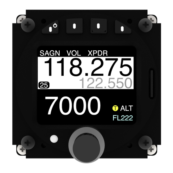
avionics 5. Combined Functions COM and XPDR Combined COM Channel Softkey Transponder (XPDR) softkey "Say Again" softkey Active COM channel SAGN XPDR 118.275 122.550 Standby COM channel 7000 Transponder mode (Altitude) FL222 Transponder squawk-code Transponder transmitted altitude Figure 5.2.: User interface with COM and transponder functions combined. COM and Altimeter Combined COM Channel Softkey QNE Softkey (Sets barometric... -
Page 34: Xpdr And Altimeter Combined
avionics 5. Combined Functions XPDR and Altimeter Combined Transponder Mode Softkey Ident Softkey BARO Softkey IDNT BARO 7000 Transponder squawk-code Transponder mode (Altitude) FL222 Altitude display unit 22250 Current altitude Transponder transmitted altitude Tape-style altitude indication 22200 1013.2 Barometric reference Figure 5.4.: User interface with transponder and altimeter functions combined. -
Page 35: System Con Guration
System Con guration Con guration Operations Con guration Menu ACD-57 is con gured in the con guration menu. To enter the con guration menu, push the inner knob pushbutton for at least 2 seconds (long push). The menu contains several con guration options and informations about ACD-57 and connected systems. - Page 36 avionics 6. System Con guration 2. Use the inner knob to navigate to DEVICE ILLUMIN OVERRIDE 3. Once the illumination override page is entered, the illumination con guration is shown. Use the inner knob to override the illumination con guration and to enter a manual value.
-
Page 37: Altimeter Con Guration
avionics 6. System Con guration Altimeter Con guration The ALTIMETER menu section contains speci c con guration parameters for the integrated altimeter. Units Units for altitude and pressure are user con gurable. Altitude units con gurable to meters or feet Pressure units con gurable to hectopascals (millibars) or inches of mercury The default settings are meters and hectopascals. -
Page 38: Acd-57 Com Control Con Guration
avionics 6. System Con guration ACD-57 COM Control Con guration The COM CONTROL menu section contains setup parameters for the control of a connected COM system. Channel Spacing The current channel spacing used in the ACD-57 can be selected in this parameter. It can be set to both, 25kHz, or 8.33kHz. - Page 39 avionics 6. System Con guration SAGN XPDR SAGN XPDR 118.275 118.275 WALLDORF INFO 122.550 122.550 7000 7000 FL222 FL222 SAGN NRST SAGN NRST 118.275 118.275 WALLDORF INFO 129.970 129.970 MALSCH GLD Figure 6.2.: COM main page with STATION NAMES parameter set to ON on the left and to OFF on the right.
- Page 40 avionics 6. System Con guration SAGN NRST SAGN NRST 118.275 118.275 WALLDORF INFO WALLDORF INFO 129.970 129.970 MALSCH GLD MALSCH GLD Figure 6.3.: COM main page with KNOB USE parameter set to VOLUME on the left and to CHANNEL on the right. In aircraft with no audio panel or intercom, we recommend to use the default setting (KNOB USE set to VOLUME).
-
Page 41: Connected Com System Con Guration
avionics 6. System Con guration Connected COM System Con guration The COM SYSTEM section contains setup parameters for a connected VHF transceiver. Depending on the type of connected VHF transceiver, di erent parameters are available. Where possible, menu parameter names are consistent to parameter names in the VHF transceiver’s documentation. -
Page 42: Acd-57 Xpdr Control Con Guration
avionics 6. System Con guration ACD-57 XPDR Control Con guration The XPDR CONTROL section contains setup parameters for the control of a connected XPDR system. VFR Preset Here a preset value for the VFR squawk code can be entered. This value is used when the VFR Softkey is pressed on the XPDR page. -
Page 43: Connected Xpdr System Con Guration
avionics 6. System Con guration Connected XPDR System Con guration The XPDR SYSTEM section contains setup parameters for a connected XPDR system. Please consult the XPDR system’s documentation for details on parameters and recommended values. Flight ID In this menu, a ight ID can be entered. The ight ID must correspond to the aircraft identi cation speci ed in item 7 of the ICAO ight plan, or, when no ight plan has been led, the aircraft registration. -
Page 44: Version Identi Cation
Software and Station Database Updates Version Identi cation The software version can be reviewed in CONFIGURATION MENU DEVICE INFO. Software/Database Loading Software updates and the station database are loaded using the integrated microSD card slot and a microSD memory card. While the software is actually loaded onto the device, the station database remains on the microSD card. - Page 45 Using a Station Database To use a database, please carry out the following steps: 1. Purchase a valid station database le in the AIR Avionics License Store. Please visit http://www.air-avionics.com/license for details. 2. Load the station database le onto a microSD card.
- Page 46 avionics 7. Software and Station Database Updates The station database and related functions are only available while the microSD card holding the station database le is inserted. If the microSD card is removed, the database and all related functions are unavailable. Loading Software to ACD-57 For details on loading new software onto ACD-57, please consult the ACD-57 Installation Manual [1].
-
Page 47: Failures
Failures and Abnormal Operation ACD-57 features a range of built-in self test features that continuously monitor system state and the state of connected systems to detect failures. Failures The detection of a failure is always annunciated to the ight crew on the display. Depending on detected failure and failure severity, the system may seize to function or functionality may be limited. -
Page 48: Systems Failures
avionics 8. Failures and Abnormal Operation If devices are configured but not connected, they are crossed out: SAGN VOL XPDR 7000 FL222 Figure 8.2.: No data/communication with connected COM system. No GPS Data and/or No Database Installed Some functions require a Database on an inserted microSD memory card and valid GPS position data. - Page 49 avionics 8. Failures and Abnormal Operation Fatal Failures In case of a fatal failure, the failed system has seized operation. This can not be recovered during runtime, a restart is required. A fatal failure message is displayed in red color and will remain visible for the rest of the runtime of the system.
-
Page 50: Bibliography
Bibliography [1] AIR Avionics, ACD-57: Installation Manual, January 2017. ACD-57 Pilot’s Manual rev. 1.0 2017/01/19... -
Page 51: Con Guration Menu Diagram
Con guration Menu Diagram This menu diagram only shows the basic con guration parameters accessible to the ight crew. For a complete menu diagram including all pin code protected parameters, please consult the ACD-57 Installation Manual [1]. PID: Product iden- ti cation VID: Vendor iden- ti cation/manufac-... -
Page 52: Con Guration Menu Diagram
avionics B. Con guration Menu Diagram VFR PRESET: VFR squawk code pre- set con guration XPDR CONTROL page: Values from 0000 to 7777. De- fault is 7000 Con guration FLIGHT ID: Flight Menu ID con guration page: 8 Charac- ters XPDR SYSTEM SW VERSION: Cur- rent XPDR system... -
Page 53: Com Control Only Softkeys
Softkey Menu Diagram COM Control Only Softkeys SAGN: Activates say again function. Only available if COM connected unit supports this function CNCL: Cancels back to the main page NRST: Opens the nearest station page ESC: Escapes back to main page EDIT: Edits the CHN: Opens the highlighted chan-... -
Page 54: Xpdr Control Only Softkeys
avionics C. Softkey Menu Diagram XPDR Control Only Softkeys MDE: changes the XPDR mode IDNT: Initiates the ident function CNCL: Cancels MAIN PAGE back to the main page VFR: selects the Rotate Any Knob: VFR preset squawk Opens the XPDR code page MDE: changes the... -
Page 55: Xpdr Control And Altimeter Softkeys
avionics C. Softkey Menu Diagram Please note that depending on the setup of the KNOB USE parameter, the CHN softkey on the main page may be replaced by a VOL softkey (volume control) and rotation of inner knob or outer knob will open the channel selection page. XPDR Control and Altimeter Softkeys MDE: changes the XPDR mode... -
Page 56: Com, Xpdr Control, And Altimeter Softkeys
avionics C. Softkey Menu Diagram COM, XPDR Control, and Altimeter Softkeys SAGN: Activates say again function. Only available if COM connected unit supports this function CNCL: Cancels back to the main page NRST: Opens the nearest station page ESC: Escapes back to main page EDIT: Edits the CHN: Opens the... -
Page 57: Com Operation
Quick Reference List softkey 1 (function "CNCL") softkey 2 softkey 1 and softkey 3 ON/OFF button softkey 4 inner knob inner knob pushbutton outer knob Figure D.1.: ACD-57 pilot controls Switch On or O If not switching on automatically, push softkey 1 , the leftmost button on top of the display, to switch the unit on. -
Page 58: Xpdr Operation
avionics D. Quick Reference List XPDR Operation Squawk Code Entry The squawk code is entered in the XPDR page. The XPDR page is opened by pushing the XPDR softkey on the main page. On the XPDR page, use the outer knob to select a position in the squawk code and use the inner knob to adjust the selected position’s value.
Need help?
Do you have a question about the AIR Control Display 57 and is the answer not in the manual?
Questions and answers