Chapters
Table of Contents

Related Manuals for air avionics AIR Traffic


Summary of Contents for air avionics AIR Traffic
- Page 1 avionics AIR Tra c Installation Manual Tra c Avoidance System Document: MAN0070A0001 Version: Date: 2020/01/09 Phone: +49 (0) 6224 82 83 87 0 Fax: +49 (0) 6224 82 83 87 7 Internet: https://www.air-avionics.com Mail: support@air-avionics.com...
- Page 2 avionics AT-1 Installation Manual rev. 4.0 2020/01/09...
- Page 3 Important Please read this manual carefully before installing the device. Please observe the limitations and safety instructions. This manual is an essential portion of the device and shall be kept in a safe place. Articles Covered This manual covers the following articles: AT-1 ‘‘AIR Tra c’’...
-
Page 4: Table Of Contents
Contents General Description Introduction Equipment Description System Capabilities Technical Speci cations Regulatory Compliance Liability Unpacking and Inspecting Equipment Installation Materials System Interconnects D-SUB Power/Data Connectors USB Connector Antenna Connectors Static Pressure Port Interfaces Serial Data Interface ARINC429 Interface WiFi Interface Data Bus Interface Power Supply and Enable Interface Audio Output... - Page 5 avionics Contents Air Circulation and Cooling Compass Safe Distance Installation Procedures Equipment Mounting Wiring Antenna Installation Interconnect Installation Post Installation Con guration, Checkout, and Documentation Post Installation Checkout Wiring Checks Connector Engagement Checks System Con guration AT-1 Con guration Webpage Simple, Advanced, and Expert Con guration Mode Simple Con guration Expert Con guration...
- Page 6 avionics Contents Software/Database Loading Bibliography Assembly And Installation Drawings Cabling and Con guration Examples GARMIN GTN 650 and 750 GARMIN GNS 430/530 (WAAS and non-WAAS versions) Wiring Diagrams Checkout Log Installation Ground Checks Interference Checks Documentation Con guration Parameters Own Aircraft Installation Privacy Warnings...
- Page 7 avionics Contents AT1 Software Version 3 AT1 Software Version 2 AT1 Software Version 1 Environmental data AT-1 Installation Manual rev. 4.0 2020/01/09...
- Page 8 avionics Contents AT-1 Installation Manual rev. 4.0 2020/01/09...
-
Page 9: General Description
General Description 1.1 Introduction This manual is intended to provide mechanical and electrical information for use in the planning and design of an installation of the Air Tra c (AT-1) into an aircraft. This manual is not a substitute for an approved airframe-speci c maintenance manual, installation design drawing, or complete installation data package. -
Page 10: System Capabilities
EASA Minor Change Approvals or Supplementary Type Certi cates (STC) that have been created by AIR Avionics or third-party organisations. AT-1 cannot be used as a replacement for certi ed TAS/TCAS systems. It may not be used as a substitute for these systems, especially, not in cases where the installation of TAS/TCAS systems is mandated. -
Page 11: Regulatory Compliance
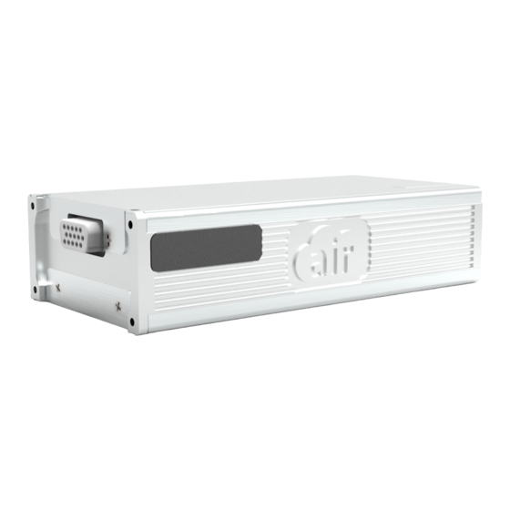
avionics 1. General Description 1.4.3 Hardware AT-1 has an all-metal housing. It features two power/signal connectors (D-SUB), four RF connectors, an optional static port connector, a USB port for data exchange, and an integrated WiFi antenna for wireless connectivity. The device status is presented using three multi-color LEDs on the back of the unit. Connector 2 (D-SUB 15HD) USB Connector Device Label... - Page 12 avionics 1. General Description 1.5.4 Telecommunication Standards and Conformity Declaration Garrecht Avionik GmbH, as the device manufacturer declares that the apparatus AIR Tra c (AT-1) in all versions conforms with the essential requirements and other relevant provisions of the following directives and complies with the following standards: Tra c Transceiver Directive Harmonized Standard applied...
-
Page 13: Liability
1 x GPS Antenna B575 Active GPS Antenna for cockpit installation (QMA) Should there be missing parts or spare parts required, please contact AIR Avionics or visit http://www.air- store.eu 1.8 Installation Materials For obtaining installation material or tools, please visit http://www.air-store.eu or contact the AIR Avionics support. - Page 14 avionics 1. General Description 1.8.2 Parts Required but not Supplied AT-1 is intended for use with standard aviation accessories. The following items are required for installation, but not supplied. Wire (MIL-W-22759/16 or equivalent) Shielded wire (MIL-C-27500 or equivalent) Push/Pull (manually resettable) circuit breakers Tie wraps or lacing cord 1.8.3 Optional Accessories You can get optional accessories from http://www.air-store.eu.
-
Page 15: System Interconnects
System Interconnects AT-1 contains various connectors for power, data, and antennas. Connector 1 USB Connector D-SUB 26HD USB C 3.1 GPS Antenna Connector QMA Female 1090MHz Antenna Connector rpSMA Female FLARM Antenna Connector A FLARM Antenna Connector B SMA Female SMA Female Connector 2 D-SUB 15HD... -
Page 16: Port 2 Receive Data (Rxd2)
avionics 2. System Interconnects 2.1.1 Connector 1 Figure 2.2.: Connector 1 pin map Pin Name Pin number Aircraft Power (VIN) RS-232 Port 1 receive data (RXD1) RS-232 Port 2 receive data (RXD2) RS-232 Port 3 receive data (RXD3) Aircraft Ground (GND) –... -
Page 17: Usb Connector
avionics 2. System Interconnects 2.1.2 Connector 2 Figure 2.3.: Connector 2 pin map Pin Name Pin number Aircraft Power Out (VOUT) RS-232 Port 2 transmit data (TXD2) RS-232 Port 2 receive data (RXD2) Enable (EN) Aircraft Ground (GND) – Aircraft Power Out (VOUT) Data Bus Low Signal (CANLO) In/Out Data Bus High Signal (CANHI) -
Page 18: Antenna Connectors
avionics 2. System Interconnects Figure 2.4.: USB connector and supplied extension cable AT-1 does not supply enough power to charge personal devices via USB. Only connect USB thumb drives to the USB port. Connecting smartphones, tablets, or PCs may damage AT-1. If an overcurrent is detected, i.e. if a device draws more current from the USB port than speci ed, the USB power supply is switched o until AT-1 is restarted. -
Page 19: Static Pressure Port
avionics 2. System Interconnects 2.4 Static Pressure Port For some of its functions, AT-1 measures the barometric altitude. The unit features an integrated pressure sensor. For more precise readings, this pressure sensor can be connected to the aircraft’s static pressure port using an optional static pressure port connector. Figure 2.6.: The static port pressure connector can be optionally installed. -
Page 20: Interfaces
Interfaces 3.1 Serial Data Interface AT-1 is capable of interfacing with other aviation instruments by sending and/or receiving serial data on its three serial data ports. All three serial data ports can be con gured individually. Pin Name Pin number RS-232 Port 1 data out (TXD1) 1.11 RS-232 Port 1 data in (RXD1) -
Page 21: Arinc429 Interface
‘‘Compatibility Considerations’’ on page 29 for details. 3.4 Data Bus Interface AT-1 uses a CAN data bus interface to connect to other AIR Avionics devices such as for example tra c display units. Only AIR Avionics articles intended for use with AT-1 may be connected to the data bus. -
Page 22: Power Supply And Enable Interface
(recommended). AT-1 sends and receives data using the CANaerospace protocol. For a detailed description of supported datasets, please contact AIR Avionics support. 3.5 Power Supply and Enable Interface 3.5.1 Power Supply The power inputs on connector 1 provide power. It is recommended to connect multiple power pins and multiple ground pins. - Page 23 avionics 3. Interfaces Pin Name Pin number Aircraft Power 1.1/1.10 Aircraft Ground 1.5/1.9/1.23/1.26 – We recommend the installation of a 3A manually resettable circuit breaker in the power supply line, e.g. a Sensata Klixon 7277-2-3. Using such a circuit breaker ensures that the AT-1 can be switched o by the ight crew if required.
-
Page 24: Audio Output
avionics 3. Interfaces 1.22 ENABLE (EN) 2.14 SWITCH 1.22 ENABLE (EN) 2.14 Figure 3.3.: If the AT-1 is not installed in combination with an AIR Tra c Display, or another device compatible to the enable-interface, either Pin 1.22 or pin 2.4 have to be connected to GND. -
Page 25: Discrete Inputs
avionics 3. Interfaces 3.7 Discrete Inputs AT-1 features a range of discrete inputs. Active-Low discrete inputs are considered active if either the voltage to ground is below a certain minimum or if the resistance to ground is below approximately 300 Ohms. These inputs can optionally be used together with switches or pushbuttons in the airframe or instrument panel to trigger speci c functions once the switch source is exercised: Function Name... -
Page 26: Installation Overview
Installation Overview 4.1 General Handling Recommendations 4.1.1 ESD Handling Recommendations To avoid damage to the AT-1, take precautions to prevent Electrostatic Discharge (ESD) when handling the unit, connectors, and associated wiring. ESD damage can be prevented by touching an object that is of the same electrical potential as the unit before handling the unit itself. -
Page 27: Cabling And Wiring Considerations
avionics 4. Installation Overview Pictorial Reference On http://workmanship.nasa.gov a pictorial reference ‘‘intended to provide insight to certi ed operators, inspectors and instructors who visually assess the compliance of ight hardware to locally applicable requirements’’ is available. 4.3 Cabling and Wiring Considerations 4.3.1 General Wiring Considerations Wiring should be installed in accordance with applicable regulations. -
Page 28: Antenna Considerations
avionics 4. Installation Overview 4.4 Antenna Considerations Good antenna placement and installation is important. FLARM signals are transmitted with very low power. Therefore, a good antenna installation is critical for equipment performance. Also the 1090 MHz and GPS antennas do have to be installed following certain requirements. If antennas are not installed in an optimum position, range and coverage are limited. - Page 29 avionics 4. Installation Overview One cockpit antenna comes included with delivery. Using a second FLARM antenna may provide better results as the reception coverage would be increased. The following locations have proven to be good places for installation of cockpit antennas. Other places may be suitable as well.
- Page 30 avionics 4. Installation Overview Figure 4.2.: Cockpit antenna reception/radiation pattern FLARM External Antennas In aircraft that are mostly made of conductive materials such as metal or carbon ber, we recommend the installation of at least one external antenna for FLARM. Normally, such an external antenna would be placed underneath the fuselage of the aircraft.
- Page 31 avionics 4. Installation Overview FLARM B EXTERIOR ANTENNA FLARM A EXTERIOR AIRCRAFT TRANSPONDER ANTENNA ANTENNA If the fuselage is not made of metal, the antenna has to be mounted on a conductive surface of at least 20cm in diameter. Always install FLARM antennas vertically Ensure that the antenna cable is routed away from the antenna in an orthogonal way.
- Page 32 avionics 4. Installation Overview 1090 MHz Cockpit Antennas In most cases, the cockpit antennas included with delivery are su cient for good operation. Although not being as critical as FLARM antennas, make sure the requirements below are met for optimum performance. 1.
- Page 33 avionics 4. Installation Overview Figure 4.6.: Cockpit antenna reception/radiation pattern 1090 MHz External Antennas In larger aircraft that are mostly made of conductive materials such as metal or carbon ber, installing an external antenna for 1090 MHz may be bene cial for optimum performance. Normally, such an external antenna would be placed underneath the fuselage of the aircraft.
- Page 34 avionics 4. Installation Overview If the fuselage is not made of metal, the antenna has to be mounted on a conductive surface of at least 20cm in diameter. Always install 1090MHz antennas vertically Ensure that the antenna cable is routed away from the antenna in an orthogonal way. Figure 4.7.: External 1090 MHz antenna Figure 4.8.: External antenna reception/radiation pattern 4.4.4 GPS Antennas...
-
Page 35: Pressure Tubing Considerations
avionics 4. Installation Overview 2. Do not coil the antenna cable. 3. Do not paint or cover the antenna. 4. Ensure that no conductive parts (metal, carbon ber) are located above of the antenna. Conductive, grounded parts below of the antenna may improve GPS antenna performance. -
Page 36: Mounting Considerations
Two mounting options are possible: AT-1 can be mounted remotely in a mounting tray or mounting rack. AT-1 can be directly attached to an AIR Avionics AIR Tra c Display (ATD-57 or ATD-80). Figure 4.10.: AT-1 mounted in a tray. -
Page 37: Compatibility Considerations
AT-1. Device Make Interface 3D Tra c Non BRG Setup. Display Tra c AIR Tra c Display ATD-XX AIR Avionics RS232 NMEA Butter y Display 57 B102 AIR Avionics RS232 NMEA – Butter y Display B101 AIR Avionics RS232 NMEA –... - Page 38 avionics 4. Installation Overview 4.7.2 Compatible Navigation Systems Panel-Mount EFIS/Navigation Systems The following panel-mount systems are compatible to the AT-1. Device Status Make Interface 3D Tra c Non BRG Setup Display Tra c GNS430/520/W Tested. Ver. 6.03 GARMIN ARINC429 – GTN650/750 Tested.
-
Page 39: Air Circulation And Cooling
The following navigation apps have been tested to be compatible to AT-1. Make Interface/ 3D Tra c Non BRG Setup. and Protocol Display Tra c updates iGlide/iPilot AIR Avionics WiFi/NMEA – Skydemon Skydemon WiFi/NMEA – AirNav Pro XAMPLE WiFi/NMEA –... -
Page 40: Installation Procedures
Installation Procedures We recommend installing AT-1 following these steps: 1. Equipment mounting. 2. Manufacturing and testing of wiring harness or selection of standard accessories. 3. Wiring harness and interconnect installation. 4. Antenna installation. 5. Post installation con guration, checkout, and documentation. 5.1 Equipment Mounting 5.1.1 Using a Mounting Tray 1. - Page 41 avionics 5. Installation Procedures Figure 5.2.: AT-1 installation in the tray. Figure 5.3.: AT-1 mounted in a tray with dimensions. 5.1.2 Using an AIR Tra c Display (ATD-57 or ATD-80) In order to install the AT-1 on an AIR Tra c Display 57 (ATD-57), a mounting kit with bracket and small parts is required (B584).
-
Page 42: Wiring
avionics 5. Installation Procedures Figure 5.4.: Exploded drawing of ATD-57, AT-1, and all small parts of the optional mounting kit. Figure 5.5.: Exploded drawing of ATD-57, AT-1, and all small parts of the optional mounting kit. 1. Prior to installation of the combination of ATD and AT-1, if already installed, please uninstall the ATD. -
Page 43: Antenna Installation
avionics 5. Installation Procedures SPEC aviation wire, crimp contacts, and ‘‘Quicklock’’ D-Sub backshells. Wiring diagrams for most common installation cases are given in appendix D. In some cases standard accessories may be used. Appendix C shows a list of example installations using standard accessories as well as recommended con guration parameters for these installations. -
Page 44: Post Installation Checkout
Post Installation Checkout This chapter contains instructions for checking out an AT-1 installation. Checks shall ensure that the system is properly installed and functions correctly. 6.1 Wiring Checks Verify that all cables are properly secured. Check the movement of aircraft controls to verify that there is no interference between the cabling and the controls. -
Page 45: System Con Guration
System Con guration In order to work properly, AT-1 must be con gured for the installation environment. For example, the own aircraft’s identi cation shall be entered in order to avoid nuisance tra c warnings resulting from reception of signals transmitted by the own aircraft. AT-1 can be con gured in several ways: 1. -
Page 46: Simple, Advanced, And Expert Con Guration Mode
avionics 7. System Con guration *AT1-00003* P/N: AT-1-(00000) ADS-B 1090-in, Flarm 868/915 MHz in/out RTCA DO-160G: D1ZBAB[UFF1]XXXXXXZBBBAC[TT]M[A2XXX]XXAX 9-32 V DC Figure 7.1.: AT-1 serial number sticker Opening the AT-1 Con guration Webpage 1. Open a web browser in your personal device. 2. -
Page 47: Simple Con Guration
avionics 7. System Con guration 7.2.2 Change Highlighting All parameters that have been changed during the current con guration session (while the AT-1 is running), are highlighted in magenta color. Figure 7.2.: Parameters on the AT-1 con guration webpage. The upper parameter has not been changed, the lower one has been changed and is shown in magenta. -
Page 48: Expert Con Guration
avionics 7. System Con guration 7.3.4 WiFi Interface Output Selects the data output for the WiFi Interface. We recommend using the FLARM protocol or the GDL90 protocol, depending on your app’s requirements. 7.3.5 RS-232 Data Port 1 Output Selects the data output for the RS-232 data port 1. This data port is normally used to provide other avionics systems like Mode-S transponders, emergency locator transmitters (ELT), or the AIR Control Display with NMEA 0183 GPS data. -
Page 49: Ground Checks
Ground Checks 8.1 Simulator for Ground Checks In order to ground-check AT-1 e ciently, a comprehensive simulator function has been implemented. The simulator is capable of simulating: Several valid or invalid GPS positions, pressure altitude and ground speed of the own aircraft. -
Page 50: Discrete Inputs Check
1. AT-1 plays a test sound every time it is switched on. The test sound is either a test beep or the phrase ‘‘AIR TRAFFIC’’ (if the voice output is activated). AT-1 Installation Manual rev. 4.0 2020/01/09... -
Page 51: Version / Revision Check
avionics 8. Ground Checks 2. Verify that the test sound is played correctly. 3. If a potentiometer is used for volume control, verify its correct operation by changing the level with the potentiometer. Every time the volume level is changed using the potentiometer, a volume indication test beep is played. -
Page 52: System Status And Error Messages
For details on failures and abnormal operation, please consult the AT-1 Pilot’s Manual [1]. For a comprehensive list of possible failure modes and corresponding error messages, please consult the AIR Avionics Error Message index [?] 9.1 Status LED 9.1.1 LED Positions The device status of the AT-1 is shown using three multi-color LEDs located in the back of the AT-1 unit. - Page 53 avionics 9. System Status and Error Messages 9.1.3 Lighting Patterns Normal Operation: Status LED 1 Status LED 1 Pattern LED 1 Color Fatal error/failure, 1090 MHz receiver module unavailable. Last dataset from 1090 MHz receiver module has been received over 30 seconds ago. Last dataset from 1090 MHz receiver module has been received over 3 seconds ago.
- Page 54 avionics 9. System Status and Error Messages Normal Operation: Status LED 3 Status LED 3 Pattern LED 3 Color Fatal error/failure, AT-1 main system unavailable. Fatal error of GPS or WiFi, for example, GPS antenna not connected Last GPS position has been received over 30 seconds ago or never.
- Page 55 avionics 9. System Status and Error Messages Status LED Patterns for Maintenance Operation Status LED 1 LED 2 LED 3 Searching for USB thumb blue blue blue drive after power-on Reading con guration from blue blue USB thumb drive Reading con g. from USB blue blue green...
-
Page 56: Status Information On Con Guration Webpage
avionics 9. System Status and Error Messages Bootloader/Update Operation Situation LED 1 LED 2 LED 3 Initializing bootloader magenta Bootloader initialized magenta successfully Flash checked: no magenta magenta application installed Flash checked: magenta application installed ok Flash checked: magenta magenta magenta incompatible application Bootloader processing a... - Page 57 avionics 9. System Status and Error Messages Figure 9.2.: Screenshot of the ‘‘Device Info’’ section in the AT-1 con guration web page AT-1 Installation Manual rev. 4.0 2020/01/09...
-
Page 58: Con Guration And Checkout Documentation
Con guration and Checkout Documentation 10.1 Con guration Documentation It is mandatory for each con guration that the con guration is logged in a document that is added to the aircraft records. The AT-1 con guration webpage features a print button for easier con guration log- ging. -
Page 59: Maintenance
We recommend updating the AT-1 software on a yearly basis, for example during the aircraft’s annual inspection. AIR Avionics o ers software package les including all software for the various submodules that are integrated in an AT-1. Software for the FLARM transceiver module, the 1090 MHz receiver module, the WiFi module, and the core module is included in a single le. - Page 60 avionics 11. Maintenance 11.2.2 Loading an Obstacle Database To install an obstacle database, please carry out the following steps: 1. Purchase a valid obstacle database le from https://www. arm.com. 2. Load the obstacle database le onto a USB thumb drive into the root folder (main folder, no subfolder).
-
Page 61: Bibliography
Bibliography [1] AIR Avionics, AT-1: Pilot’s Manual EN, August 2018. AT-1 Installation Manual rev. 4.0 2020/01/09... -
Page 62: Assembly And Installation Drawings
Assembly And Installation Drawings Figure B.1.: Dimensional drawing, all dimensions in millimeters AT-1 Installation Manual rev. 4.0 2020/01/09... -
Page 63: Cabling And Con Guration Examples
Cabling and Con guration Examples C.1 GARMIN GTN 650 and 750 For connection to a GARMIN GTN, the ARINC429 data interface is used. Any of the four ARINC429 inputs of the GTN750 and any of the two ARINC 429 data inputs of the GTN650 can be used. - Page 64 avionics C. Cabling and Con guration Examples Please note that GNS does not support obstacle and alert zone warnings. Please note that the GNS is only capable of displaying tra c on the map if it is connected to a heading source. Depending on requirements, AT-1 can be used as a heading source.
-
Page 65: Wiring Diagrams
Wiring Diagrams AT-1 AIR TRAFFIC Aircraft Power (VIN) AIRCRAFT POWER (+) 9V to 32VDC Aircraft Power (VIN) 3A CIRCUIT BREAKER AIRCRAFT GROUND (-) Aircraft GND (GND) AIRCRAFT GROUND (OPTIONAL) Aircraft GND (GND) AIRCRAFT GROUND (OPTIONAL) Aircraft GND (GND) AIRCRAFT GROUND (OPTIONAL) - Page 66 ARINC429 IN B ARINC429 Out B (A429B) ATD-11/57/80 Aircraft Power (VIN) Relay Out (ROUT) SIGNAL AS SWITCHED BY RELAY AIR TRAFFIC DISPLAY NOT CONNECTED Aircraft Power (VIN) Relay In (RIN) SIGNAL TO BE SWITCHED BY RELAY Aircraft Ground (GND) RS232 DATA INTERFACE TO NMEA DATA SOURCE...
-
Page 67: Checkout Log
Checkout Log E.1 Installation The installation has been performed in accordance with the instructions shown in this manual. Wiring checks have been performed. Connector engagement checks have been performed. E.2 Ground Checks Serial interface checks have been performed. / Check not required. ARINC429 interface check has been performed. -
Page 68: Con Guration Parameters
Con guration Parameters F.1 Own Aircraft F.1.1 Own ICAO Address (HEX) Description To identify signals from the own transponder, AT-1 uses the aircraft’s unique ICAO 24 bit address, also called ’HEX Code’ . Entering this code is mandatory for AT-1 to function properly. If your aircraft does not have an ICAO address, for example, because you do not have a Mode-S Transponder or 406MHz ELT installed and, therefore, no ID has been assigned to your aircraft yet, please enter ’FFFFFF’... -
Page 69: Installation
avionics F. Con guration Parameters F.2 Installation F.2.1 Use Own Mode-S Altitude Signal Description Activating this option disables the integrated pressure sensor and uses the pressure altitude encoded into the own aircraft’s transponder replies. Only recommended in pressurized aircraft and if the static port of the AT-1 cannot be used. Item Code: MODESALT Valid Values: ON, OFF Default Value: OFF... -
Page 70: Privacy
avionics F. Con guration Parameters F.3 Privacy F.3.1 No-Track Mode Description Enables the FLARM no-track option. If enabled, the own ship will not be tracked by ground-based receivers, e.g. by FlightRadar24 or OpenGliderNet. Item Code: FLARMNOTRACK Valid Values: ON, OFF Default Value: OFF F.3.2 Stealth Mode Description... -
Page 71: Warnings
avionics F. Con guration Parameters F.4 Warnings F.4.1 Warnings On-Ground Description Enable warnings while the aircraft sits on the ground or moves slower than the On-Ground Threshold Speed. If this parameter is disabled, warnings are suppressed on ground. Item Code: WARNONGND Valid Values: ON, OFF Default Value: OFF F.4.2 On-Ground Threshold Speed [m/s]... - Page 72 avionics F. Con guration Parameters Valid Values: integer value, 0 - 1000000 Default Value: 50 F.4.5 Protection Volume 1 Warnings Threat Level Description Threat level (i.e. warning severity) of a target inside the protection volume 1. Be very careful! Do not change this value unless you know exactly what you are doing. Adjusting this parameter wrongly may suppress tra c warnings or inadequately lower threat levels.
- Page 73 avionics F. Con guration Parameters Description Threat level (i.e. warning severity) of a target inside the protection volume 2. Be very careful! Do not change this value unless you know exactly what you are doing. Adjusting this parameter wrongly may suppress tra c warnings or inadequately lower threat levels. Item Code: PROTECTLEVEL2 Valid Values: MIN_0, MAX_0, MIN_1, MAX_1, MIN_2, MAX_2, MIN_3, MAX_3 Default Value: MIN_0...
- Page 74 avionics F. Con guration Parameters F.4.12 Protection Volume 4 Range [m] Description Adjusts the horizontal size of the ’protection volume 4’ . Inside this volume, independent from ight vectors, a certain threat level is set for any tra c target. Protection Volume 4 has the lowest priority.
-
Page 75: Digital And Analog Inputs
avionics F. Con guration Parameters F.5 Digital and Analog Inputs F.5.1 Digital Input 1 Function Description Selects the function of the digital input 1 pin. If the pin is active, the selected function is executed. The MUTE option mutes the audio output. The NO ALARM option suppresses tra c warnings. - Page 76 avionics F. Con guration Parameters Valid Values: ACTLOW, ACTOPEN Default Value: ACTLOW F.5.5 Digital Input 3 Function Description Selects the function of the digital input 3 pin. If the pin is active, the selected function is executed. The MUTE option mutes the audio output. The NO ALARM option suppresses tra c warnings.
-
Page 77: Audio Output
avionics F. Con guration Parameters F.6 Audio Output F.6.1 Audio Output Mode Description Selects the mode of operation for the audio output pin, i.e. the type of signals that are emitted. O disables the audio ampli er to save power. Item Code: AUDIOMODE Valid Values: OFF, BEEP, VOICE Default Value: BEEP... -
Page 78: Relay
avionics F. Con guration Parameters F.7 Relay F.7.1 Relay Mode Description Selects the mode of operation for the relay pins. The relay can be closed (contact between relay input and output pins is established) or opened (contact between input and output pins is interrupted) if targets are detected inside of the relay volume. -
Page 79: Flight Data Recorder
avionics F. Con guration Parameters F.8 Flight Data Recorder F.8.1 Flightlog Format Description Selects the le format in use while downloading ight les onto the USB thumb drive. Item Code: FLIGHTLOGFORMAT Valid Values: IGC, KML Default Value: KML AT-1 Installation Manual rev. 4.0 2020/01/09... -
Page 80: Wifi Interface
avionics F. Con guration Parameters F.9 WiFi Interface F.9.1 WiFi Interface Activation Description Gives options to activate the integrated WiFi interface. If not using an in- ight WiFi data connection, we recommend setting this option to ’First 15 Minutes On’ . This allows WiFi functions like the AT-1 con guration webpage to be accessed within the rst 15 minutes after power-on. - Page 81 avionics F. Con guration Parameters F.9.5 WiFi Interface Vertical Range [m] Description Vertical range limit. Targets outside of this vertical range (di erential altitude) are not transmitted over this data output. Item Code: VRANGEW Valid Values: integer value, 0 - 1000000 Default Value: 1000 F.9.6 WiFi Interface Non-Bearing Range [m] Description...
- Page 82 avionics F. Con guration Parameters Default Value: ON F.9.10 WiFi Interface GPGGA Description Activates the output of the $GPGGA dataset. GPGGA is a GPS dataset. Item Code: NMEAGPGGAW Valid Values: ON, OFF Default Value: ON F.9.11 WiFi Interface GPGSA Description Activates the output of the $GPGSA dataset.
- Page 83 avionics F. Con guration Parameters Valid Values: ON, OFF Default Value: ON F.9.15 WiFi Interface PFLAO Description Activates the output of the $PFLAO dataset. PFLAO is an alert zone info dataset in the FLARM data protocol. Item Code: NMEAPFLAOW Valid Values: ON, OFF Default Value: ON F.9.16 WiFi Interface PFLAQ Description...
- Page 84 avionics F. Con guration Parameters Description Activates the output of the $PAAVE dataset. PAAVE is an error dataset in the AAV data protocol. Item Code: NMEAPAAVEW Valid Values: ON, OFF Default Value: OFF F.9.20 WiFi Interface PFLAU ID Description Appends an identi cation data eld to warning datasets in the FLARM data protocol. Item Code: NMEAPFLAUIDW Valid Values: ON, OFF Default Value: ON...
- Page 85 avionics F. Con guration Parameters Valid Values: ON, OFF Default Value: ON F.9.24 WiFi Interface PFLAA Non-Bearing Targets Description Activates data output of ’non-bearing targets’ in PFLAA datasets. This is recommended if the connected tra c display on this interface does explicitly support such datasets. Item Code: NMEAPFLAAMODESW Valid Values: ON, OFF Default Value: ON...
-
Page 86: Data Port
avionics F. Con guration Parameters F.10 RS-232 data port 1 F.10.1 RS-232 data port 1 Flarm Tra c Description Activates or deactivates the output of Flarm tra c for this data interface. Item Code: FLARMTRAFFIC1 Valid Values: ON, OFF Default Value: ON F.10.2 RS-232 data port 1 ADS-B Tra c Description Activates or deactivates the output of ADS-B tra c for this data interface. - Page 87 avionics F. Con guration Parameters Item Code: MODESRANGE1 Valid Values: integer value, 0 - 1000000 Default Value: 3000 F.10.6 RS-232 data port 1 Non-Bearing Vertical Range [m] Description Vertical range limit. Non-bearing targets outside of this range are not transmitted over this data output.
- Page 88 avionics F. Con guration Parameters Item Code: NMEAGPGGA1 Valid Values: ON, OFF Default Value: ON F.10.11 RS-232 data port 1 GPGSA Description Activates the output of the $GPGSA dataset. GPGSA is a GPS dataset. Item Code: NMEAGPGSA1 Valid Values: ON, OFF Default Value: ON F.10.12 RS-232 data port 1 PGRMZ Description...
- Page 89 avionics F. Con guration Parameters Description Activates the output of the $PFLAO dataset. PFLAO is an alert zone info dataset in the FLARM data protocol. Item Code: NMEAPFLAO1 Valid Values: ON, OFF Default Value: OFF F.10.16 RS-232 data port 1 PFLAQ Description Activates the output of the $PFLAQ dataset.
- Page 90 avionics F. Con guration Parameters Valid Values: ON, OFF Default Value: OFF F.10.20 RS-232 data port 1 PFLAU ID Description Appends an identi cation data eld to warning datasets in the FLARM data protocol. Item Code: NMEAPFLAUID1 Valid Values: ON, OFF Default Value: ON F.10.21 RS-232 data port 1 PFLAU Non-Bearing Targets Description...
- Page 91 avionics F. Con guration Parameters Description Activates data output of ’non-bearing targets’ in PFLAA datasets. This is recommended if the connected tra c display on this interface does explicitly support such datasets. Item Code: NMEAPFLAAMODES1 Valid Values: ON, OFF Default Value: ON F.10.25 RS-232 data port 1 PFLAA No-Track Flag Output Description Activates the data output of the FLARM no-track status ag in all PFLAA datasets.
-
Page 92: Data Port
avionics F. Con guration Parameters F.11 RS-232 data port 2 F.11.1 RS-232 data port 2 Flarm Tra c Description Activates or deactivates the output of Flarm tra c for this data interface. Item Code: FLARMTRAFFIC2 Valid Values: ON, OFF Default Value: ON F.11.2 RS-232 data port 2 ADS-B Tra c Description Activates or deactivates the output of ADS-B tra c for this data interface. - Page 93 avionics F. Con guration Parameters Item Code: MODESRANGE2 Valid Values: integer value, 0 - 1000000 Default Value: 3000 F.11.6 RS-232 data port 2 Non-Bearing Vertical Range [m] Description Vertical range limit. Non-bearing targets outside of this range are not transmitted over this data output.
- Page 94 avionics F. Con guration Parameters Item Code: NMEAGPGGA2 Valid Values: ON, OFF Default Value: ON F.11.11 RS-232 data port 2 GPGSA Description Activates the output of the $GPGSA dataset. GPGSA is a GPS dataset. Item Code: NMEAGPGSA2 Valid Values: ON, OFF Default Value: ON F.11.12 RS-232 data port 2 PGRMZ Description...
- Page 95 avionics F. Con guration Parameters Description Activates the output of the $PFLAO dataset. PFLAO is an alert zone info dataset in the FLARM data protocol. Item Code: NMEAPFLAO2 Valid Values: ON, OFF Default Value: ON F.11.16 RS-232 data port 2 PFLAQ Description Activates the output of the $PFLAQ dataset.
- Page 96 avionics F. Con guration Parameters Valid Values: ON, OFF Default Value: OFF F.11.20 RS-232 data port 2 PFLAU ID Description Appends an identi cation data eld to warning datasets in the FLARM data protocol. Item Code: NMEAPFLAUID2 Valid Values: ON, OFF Default Value: ON F.11.21 RS-232 data port 2 PFLAU Non-Bearing Targets Description...
- Page 97 avionics F. Con guration Parameters Description Activates data output of ’non-bearing targets’ in PFLAA datasets. This is recommended if the connected tra c display on this interface does explicitly support such datasets. Item Code: NMEAPFLAAMODES2 Valid Values: ON, OFF Default Value: ON F.11.25 RS-232 data port 2 PFLAA No-Track Flag Output Description Activates the data output of the FLARM no-track status ag in all PFLAA datasets.
- Page 98 avionics F. Con guration Parameters F.12 RS-232 data port 3 F.12.1 RS-232 data port 3 Flarm Tra c Description Activates or deactivates the output of Flarm tra c for this data interface. Item Code: FLARMTRAFFIC3 Valid Values: ON, OFF Default Value: ON F.12.2 RS-232 data port 3 ADS-B Tra c Description Activates or deactivates the output of ADS-B tra c for this data interface.
- Page 99 avionics F. Con guration Parameters Item Code: MODESRANGE3 Valid Values: integer value, 0 - 1000000 Default Value: 3000 F.12.6 RS-232 data port 3 Non-Bearing Vertical Range [m] Description Vertical range limit. Non-bearing targets outside of this range are not transmitted over this data output.
- Page 100 avionics F. Con guration Parameters Item Code: NMEAGPGGA3 Valid Values: ON, OFF Default Value: ON F.12.11 RS-232 data port 3 GPGSA Description Activates the output of the $GPGSA dataset. GPGSA is a GPS dataset. Item Code: NMEAGPGSA3 Valid Values: ON, OFF Default Value: ON F.12.12 RS-232 data port 3 PGRMZ Description...
- Page 101 avionics F. Con guration Parameters Description Activates the output of the $PFLAO dataset. PFLAO is an alert zone info dataset in the FLARM data protocol. Item Code: NMEAPFLAO3 Valid Values: ON, OFF Default Value: ON F.12.16 RS-232 data port 3 PFLAQ Description Activates the output of the $PFLAQ dataset.
- Page 102 avionics F. Con guration Parameters Valid Values: ON, OFF Default Value: ON F.12.20 RS-232 data port 3 PFLAU ID Description Appends an identi cation data eld to warning datasets in the FLARM data protocol. Item Code: NMEAPFLAUID3 Valid Values: ON, OFF Default Value: ON F.12.21 RS-232 data port 3 PFLAU Non-Bearing Targets Description...
- Page 103 avionics F. Con guration Parameters Description Activates data output of ’non-bearing targets’ in PFLAA datasets. This is recommended if the connected tra c display on this interface does explicitly support such datasets. Item Code: NMEAPFLAAMODES3 Valid Values: ON, OFF Default Value: ON F.12.25 RS-232 data port 3 PFLAA No-Track Flag Output Description Activates the data output of the FLARM no-track status ag in all PFLAA datasets.
-
Page 104: Arinc 429 Interface
avionics F. Con guration Parameters F.13 ARINC 429 Interface F.13.1 ARINC429 Flarm Tra c Description Activates or deactivates the output of Flarm tra c data over the ARINC429 data output. Item Code: A429FLARMTRAFFIC Valid Values: ON, OFF Default Value: ON F.13.2 ARINC429 ADS-B Tra c Description Activates or deactivates the output of ADS-B tra c data over the ARINC429 data output. - Page 105 avionics F. Con guration Parameters Item Code: A429MODESRANGE Valid Values: integer value, 0 - 1000000 Default Value: 3000 F.13.6 ARINC429 Non-Bearing Vertical Range [m] Description Vertical range limit. Non-bearing targets outside of this range are not transmitted over the ARINC429 data output. Item Code: A429MODESVRANGE Valid Values: integer value, 0 - 1000000 Default Value: 500...
-
Page 106: Changelog
Changelog G.1 AT-1 Software Version 8 Please be careful: If using an AIR Tra c Display on your AT-1, please ensure that the AIR Tra c Display is updated to version 21 or later before updating your AT-1 to this version! G.1.1 Component Versions Main Module Software Version:... -
Page 107: Software Version
avionics G. Changelog G.2 AT-1 Software Version 7 Please be careful: If using an AIR Tra c Display on your AT-1, please ensure that the AIR Tra c Display is updated to version 21 or later before updating your AT-1 to this version! G.2.1 Component Versions Main Module Software Version:... -
Page 108: Software Version
avionics G. Changelog G.3 AT-1 Software Version 6 Please be careful: If using an AIR Tra c Display on your AT-1, please ensure that the AIR Tra c Display is updated to version 21 or later before updating your AT-1 to this version! G.3.1 Component Versions Main Module Software Version:... - Page 109 avionics G. Changelog G.4 AT-1 Software Version 5 Please be careful: If using an AIR Tra c Display on your AT-1, please ensure that the AIR Tra c Display is updated to version 21 or later before updating your AT-1 to this version! G.4.1 Component Versions Main Module Software Version:...
- Page 110 avionics G. Changelog Added button to perform a factory reset to the con g website. Reordered ARINC429 interface items on the con g website to be consistent to log le. Show FLARM radio-id type on the con g website. Show FLARM obstacle db status on the con g website. Corrected description of WARNONGND item on the con g website.
- Page 111 avionics G. Changelog G.5 AT-1 Software Version 4 G.5.1 Component Versions Main Module Software Version: WiFi Module Software Version: FLARM Module Software Version: 6.62 1090MHz Receiver Module Software Version: G.5.2 Changes Since Version 3 Main Module Software Added support for hardware version 1100, 1000 and 0100. WiFi Module Software No Changes.
- Page 112 avionics G. Changelog G.6 AT1 Software Version 3 G.6.1 Component Versions Main Module Software Version: WiFi Module Software Version: FLARM Module Software Version: 6.62 1090MHz Receiver Module Software Version: G.6.2 Changes Since Version 2 Main Module Software Added GDL90 data output. Added voice functions for alarm and error announcement via audio output.
- Page 113 avionics G. Changelog Improved naming of items on the con guration webpage. Reordered ARINC429 interface items on con guration webpage to be consistent to log le. FLARM Module Software Updated FLARM core softwore from version 6.60 to version 6.62. 1090MHz Receiver Module Software No Changes.
- Page 114 avionics G. Changelog G.7 AT1 Software Version 2 G.7.1 Component Versions Main Module Software Version: WiFi Module Software Version: FLARM Module Software Version: 6.60 1090MHz Receiver Module Software Version: G.7.2 Changes Since Version 1 Main Module Software No Changes. WiFi Module Software No Changes.
- Page 115 avionics G. Changelog G.8 AT1 Software Version 1 G.8.1 Component Versions Main Module Software Version: WiFi Module Software Version: FLARM Module Software Version: 6.40 1090MHz Receiver Module Software Version: AT-1 Installation Manual rev. 4.0 2020/01/09...
- Page 116 Environmental data Environmental tests are performed in accordance with RTCA DO-160G Description Section Category Conditions Temperature / Altitude D1 ° Low Ground Survival Temperature 4.5.1 ° Low Operating Temperature 4.5.1 ° High Ground Survival Temperature 4.5.2 ° High short Time Operating Temperature 4.5.2 °...
Need help?
Do you have a question about the AIR Traffic and is the answer not in the manual?
Questions and answers