
Related Manuals for Victron energy MultiPlus 1600VA


Summary of Contents for Victron energy MultiPlus 1600VA
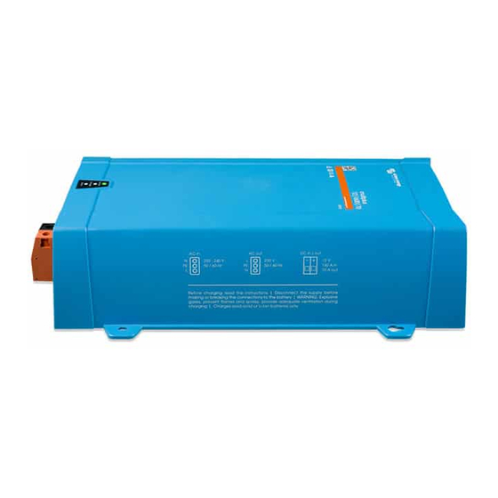
- Page 1 Manual Handleiding Manuel Anleitung Manual Manuale MultiPlus 1600VA MultiPlus 12 | 1600 | 70 230V MultiPlus 24 | 1600 | 40 230V MultiPlus 48 | 1600 | 20 230V...
-
Page 3: Safety Instructions
1. SAFETY INSTRUCTIONS General Please familiarize yourself with the safety features and instructions by first reading the documentation supplied with this product before using the equipment. This product has been designed and tested in accordance with international standards. The equipment must be used exclusively for the purpose for which it was designed. -
Page 4: Transport And Storage
Transport and Storage Ensure that the mains power and battery leads have been disconnected before storing or transporting the product. No liability can be accepted for any transport damage if the equipment is shipped in non- original packaging. Store the product in a dry environment; the storage temperature must be between -40°C and 70°C. -
Page 5: Battery Charger
2. DESCRIPTION 2.1 General Multifunctional The Multi gets its name from the multiple functions it can perform. It is a powerful true sine wave inverter, a sophisticated battery charger that features adaptive charge technology and a high-speed AC transfer switch in a single enclosure. Beside these primary functions, however, the Multi has several advanced features that provide a range of new applications as outlined below. - Page 6 Preventing damage due to excessive gassing: the BatterySafe mode If, in order to quickly charge a battery, a high charge current in combination with a high absorption voltage has been chosen, damage due to excessive gassing will be prevented by automatically limiting the rate of voltage increase once the gassing voltage has been reached.
-
Page 7: Operation
3. OPERATION 3.1 On / Off / Charger-only Switch When switched to ‘on’, the product is fully functional. The inverter will come into operation and the LED ‘inverter on’ will light up. An AC voltage connected to the ‘AC in’ terminal will be switched through to the ‘AC out’ terminal, if within specifications. -
Page 8: Led Indications
3.3 LED Indications LED off LED flashes LED illuminated Inverter/Charger/ On / Off / Charger-only switch = On The inverter is switched on and supplies power to the load. On / Off / Charger-only switch = On The inverter is switched on and supplies power to the load. Pre-alarm: overload, or battery voltage low, or inverter temperature high. - Page 9 Charger only On / Off / Charger-only switch = Charger only The AC input voltage is switched through and the charger operates in bulk or absorption mode. On / Off / Charger-only switch = Charger only The AC input is switched through and the charger operates in float or storage mode.
-
Page 10: Installation
4. INSTALLATION This product should be installed by a qualified electrician. 4.1 Location The product must be installed in a dry and well-ventilated area, as close as possible to the batteries. There should be a clear space of at least 10cm around the appliance for cooling. a. - Page 11 Internal DC Fuses 1600VA 1600VA 12V - 24V Automotive Bolt-Down Fuse MIDI or BF1 fuse 200A – 125A MIDI or BF1 fuse All servicing must be undertaken by qualified personnel. 4.3 Connection of the AC cabling This is a Safety Class I product (supplied with a protective grounding terminal). Uninterruptible protective grounding must be provided at the AC input and/or output terminals and/or chassis grounding point located externally on the product.
-
Page 12: Optional Connections
4.4 Optional Connections A number of optional connections are possible: Undo the four screws at the front of the enclosure and remove the front panel. 4.4.1 Second Battery The Multi has a connection (+) for charging a starter battery. For connection see appendix A. Trickle charge output is protected by automatic overcurrent &... - Page 13 4.4.6 Three-phase operation (see appendix D) The MultiPlus can also be used in 3-phase wye (Y) configuration. To this end, a connection between the devices is made by means of standard RJ45 UTP cables (the same as for parallel operation). The system (MultiPlus units plus an optional control panel) will require subsequently configuration (see Section 5).
- Page 14 5.2 Explanation of settings Settings that are not self-explanatory are described briefly below. For further information, please refer to the help files in the software configuration programs (see Section 5.3). Inverter frequency Output frequency if no AC is present at the input. Adjustability: 50Hz;...
- Page 15 Ground relay (see appendix B) With this relay (H), the neutral conductor of the AC output is grounded to the chassis when the back-feed safety relay is open. This ensures the correct operation of earth leakage circuit breakers in the output. If a non-grounded output is required during inverter operation, this function must be turned off.
-
Page 16: Dynamic Current Limiter
(which is quite rare!). Also turn on the dynamic current limiter simultaneously and reduce the maximum charging current to prevent overloading the generator if necessary. BoostFactor Change this setting only after consulting with Victron Energy or with an engineer trained by Victron Energy! Programmable relay By default, the programmable relay is set as an alarm relay, i.e. -
Page 17: Configuration By Computer
5.3 Configuration by computer All settings can be changed by means of a computer. Some settings can be changed with DIP switches (see Section 5.4). For changing settings with the computer, the following is required: - VEConfigure3 software: can be downloaded free of charge at www.victronenergy.com. - A MK3-USB (VE.Bus to USB) interface, and a RJ45 UTP cable. - Page 18 5.4.1. DIP switch 1 to 3 These DIP switches can be used to set: - Battery charge voltage and Absorption time - Search mode Ds1-ds2: Setting the charge algorithm Absorption Absorption Float Storage Ds1-ds2 Time Suitable for voltage voltage Voltage (hours) Gel Victron Deep Ds1=off...
-
Page 19: Maintenance
5.4.2 Exemplary settings Example 1 is the factory setting (since factory settings are entered by computer, all DIP switches of a new product are set to ‘off’). DS-1 Charge voltage DS-1 DS-1 DS-2 Charge voltage DS-2 DS-2 DS-3 Search mode DS-3 DS-3 →... -
Page 20: Troubleshooting Table
Proceed as follows for quick detection of common faults. DC loads must be disconnected from the batteries and the AC loads must be disconnected from the inverter before the inverter and/or battery charger is tested. Consult your Victron Energy dealer if the fault cannot be resolved. Problem Cause... - Page 21 Problem Cause Solution The charger is not The AC input voltage or frequency Ensure that the input voltage is functioning is out of range between 185Vac and 265Vac, and that the frequency matches the setting. The battery is not Incorrect charging current Set the charging current at being charged fully between 0.1 and 0.2x battery...
-
Page 22: Technical Data
8. TECHNICAL DATA MultiPlus 12/1600/70 MultiPlus 24/1600/40 MultiPlus 48/1600/20 PowerControl / PowerAssist Transfer switch INVERTER Input voltage range 9,5 – 17V 19 – 33V 38– 66V Output Output voltage: 230VAC ± 2% Frequency: 50Hz ± 0,1% (1) Cont. output power at 25°C (3) 1600VA Cont. - Page 23 www.victronenergy.com Appendix A: overview connections Bijlage A: overzicht aansluitingen Annexe A : Vue d’ensemble des connections Anhang A: Übersicht Anschlüsse Apéndice A: Conexiones generales Appendice A: panoramica connessioni...
- Page 24 Appendix A: overview connections Bijlage A: overzicht aansluitingen Annexe A : Vue d’ensemble des connections Anhang A: Übersicht Anschlüsse Apéndice A: Conexiones generales Appendice A: panoramica connessioni DIP switch DIP switch schakelaar Commutateur DIP switch Remove cover Verwijder cover Retirer la protection On/off/charger only switch On/off/charger only schakelaar Interrupteur...
- Page 25 www.victronenergy.com Appendix B: installation information Bijlage B: informatie installatie Annexe B : informations d'installation Anhang B: information zur Installation Apéndice B: instrucciones de instalación Appendice B: informazioni per l'installazione...
- Page 26 Appendix B: installation information Bijlage B: installatie informatie Annexe B : informations d'installation Anhang B: information zur Installation Apéndice B: instrucciones de instalación Appendice B: informazioni per l'installazione Input Ingang Entrée Output Uitgang Sortie Ground in– and output connected Aardverbinding naar behuizing Liaison à...
- Page 27 www.victronenergy.com Appendix C: parallel connection Bijlage C: parallelle aansluiting Annexe C : Connexion en parallèle Anhang C: Parallelbetrieb Apéndice C: Conexión en paralelo Appendice C: collegamento in parallelo...
- Page 28 Appendix D: three-phase connection Bijlage D: driefasige aansluiting Annexe D : connexion triphasée Anhang D: drei-Phasen-Betrieb Apéndice D: conexión trifásica Appendice D: collegamento trifase...
- Page 29 www.victronenergy.com Appendix E: charge algorithm Bijlage E: laadalgoritme Annexe E : algorithme de charge Anhang E: ladealgorithmus Apéndice E: algoritmo de carga Appendice E: algoritmo di carica 64 32 60 30 64 32 Battery Safe 56 28 mode 60 30 52 26 56 28 20 x Bulk-hours or...
- Page 30 Appendix E: charge algorithm Bijlage E: laadalgoritme Annexe E : algorithme de charge Anhang E: ladealgorithmus Apéndice E: algoritmo de carga Appendice E: algoritmo di carica Vierfasig opladen: Bulk: Ingezet wanneer de lader is opgestart. Er wordt constante stroom toegepast, totdat de gasspanning is bereikt (14,4V of 28,8V, temperatuurgecompenseerd).
- Page 31 www.victronenergy.com Appendix E: charge algorithm Bijlage E: laadalgoritme Annexe E : algorithme de charge Anhang E: ladealgorithmus Apéndice E: algoritmo de carga Appendice E: algoritmo di carica 4-stufiges Laden: Konstantstromphase (Bulk): Eingeleitet, wenn Ladegerät gestartet wird. Konstantstrom wird zugeführt, bis die nominale Batteriespannung erreicht wird.
- Page 32 Appendix F: temperature compensation Bijlage F: temperatuurcompensatie Annexe F : compensation de température Appendix F: temperaturkompensation Apéndice F: compensación de temperatura Appendice F: compensazione della temperatura Default output voltages for Float and Absorption are at 25°C. Reduced Float voltage follows Float voltage and Raised Absorption voltage follows Absorption voltage. In adjust mode temperature compensation does not apply.
- Page 33 www.victronenergy.com Appendix G: dimensions Bijlage G: afmetingen Annexe G : dimensions Anhang G: Maße Apéndice G: dimensiones Appendice G: dimensioni...
- Page 34 Serial number: Version : 04 Date : September 9 , 2019 Victron Energy B.V. De Paal 35 | 1351 JG Almere PO Box 50016 | 1305 AA Almere | The Netherlands General phone : +31 (0)36 535 97 00 E-mail : sales@victronenergy.com...
Need help?
Do you have a question about the MultiPlus 1600VA and is the answer not in the manual?
Questions and answers