
Related Manuals for WAGO 750-658


Summary of Contents for WAGO 750-658
- Page 1 Manual WAGO-I/O-SYSTEM 750 750-658 CAN Gateway Version 1.2.1, valid from FW/HW-Version 01/01...
- Page 2 We wish to point out that the software and hardware terms as well as the trademarks of companies used and/or mentioned in the present manual are generally protected by trademark or patent. WAGO is a registered trademark of WAGO Verwaltungsgesellschaft mbH. Manual Version 1.2.1, valid from FW/HW-Version 01/01...
-
Page 3: Table Of Contents
WAGO-I/O-SYSTEM 750 Table of Contents 750-658 CAN Gateway Table of Contents Notes about this Documentation .............. 6 Validity of this Documentation ..............6 Copyright....................6 Symbols ....................7 Number Notation ..................9 Font Conventions ..................9 Important Notes ..................10 Legal Bases ................... - Page 4 Connect Devices ..................44 ® Connecting a Conductor to the CAGE CLAMP ........44 Connect CAN Bus .................. 45 Configuration and Parameterization ............46 Configuration and Parameterization with WAGO-I/O-CHECK ....47 9.1.1 Configuration Dialog ................48 9.1.1.1 Toolbar ..................48 9.1.1.2 Function Area ................
- Page 5 WAGO-I/O-SYSTEM 750 Table of Contents 750-658 CAN Gateway Use in Hazardous Environments ............73 11.1 Marking Configuration Examples ............74 11.1.1 Marking for Europe According to ATEX and IECEx ......74 11.1.2 Marking for the United States of America (NEC) and Canada (CEC) ....................
-
Page 6: Notes About This Documentation
This documentation is only applicable to the I/O module 750-658 (CAN Gateway). This documentation is only applicable from FW/HW-Version 01/01. The I/O module 750-658 shall only be installed and operated according to the instructions in this manual and in the manual for the used fieldbus coupler or controller. -
Page 7: Symbols
WAGO-I/O-SYSTEM 750 Notes about this Documentation 750-658 CAN Gateway Symbols Personal Injury! Indicates a high-risk, imminently hazardous situation which, if not avoided, will result in death or serious injury. Personal Injury Caused by Electric Current! Indicates a high-risk, imminently hazardous situation which, if not avoided, will result in death or serious injury. - Page 8 Notes about this Documentation WAGO-I/O-SYSTEM 750 750-658 CAN Gateway Additional Information: Refers to additional information which is not an integral part of this documentation (e.g., the Internet). Manual Version 1.2.1, valid from FW/HW-Version 01/01...
-
Page 9: Number Notation
WAGO-I/O-SYSTEM 750 Notes about this Documentation 750-658 CAN Gateway Number Notation Table 1: Number Notation Number Code Example Note Decimal Normal notation Hexadecimal 0x64 C notation Binary '100' In quotation marks, nibble separated '0110.0100' with dots (.) Font Conventions Table 2: Font Conventions... -
Page 10: Important Notes
2.1.1 Subject to Changes WAGO Kontakttechnik GmbH & Co. KG reserves the right to provide for any alterations or modifications. WAGO Kontakttechnik GmbH & Co. KG owns all rights arising from the granting of patents or from the legal protection of utility patents. -
Page 11: Technical Condition Of Specified Devices
These modules contain no parts that can be serviced or repaired by the user. The following actions will result in the exclusion of liability on the part of WAGO Kontakttechnik GmbH & Co. KG: •... -
Page 12: 2.1.4.1.2 Packaging
Important Notes WAGO-I/O-SYSTEM 750 750-658 CAN Gateway Environmentally friendly disposal benefits health and protects the environment from harmful substances in electrical and electronic equipment. • Observe national and local regulations for the disposal of electrical and electronic equipment. • Clear any data stored on the electrical and electronic equipment. -
Page 13: Safety Advice (Precautions)
Install the device only in appropriate housings, cabinets or in electrical operation rooms! The WAGO-I/O-SYSTEM 750 and its components are an open system. As such, install the system and its components exclusively in appropriate housings, cabinets or in electrical operation rooms. Allow access to such equipment and fixtures to authorized, qualified staff only by means of specific keys or tools. - Page 14 Important Notes WAGO-I/O-SYSTEM 750 750-658 CAN Gateway Replace defective or damaged devices! Replace defective or damaged device/module (e.g., in the event of deformed contacts). Protect the components against materials having seeping and insulating properties! The components are not resistant to materials having seeping and insulating properties such as: aerosols, silicones and triglycerides (found in some hand creams).
-
Page 15: Can Technology
WAGO-I/O-SYSTEM 750 CAN Technology 750-658 CAN Gateway CAN Technology The CAN bus is an asynchronous serial bus system for connecting intelligent actuators and sensors to the control level. CAN standards for "Controller Area network" and defines a communication standard developed in the mid-1980s for data transmission in automobiles. -
Page 16: Device Description
WAGO-I/O-SYSTEM 750 750-658 CAN Gateway Device Description The I/O module 750-658 is used to connect a CAN bus network to a PLC independent of the fieldbus. The I/O module supports the physical layer and data link layer by default. Support higher protocol layers! Use IEC-61131-compliant function blocks to support the I/O module of higher protocol layers. -
Page 17: Table 4: 750-658 Compatibility List - Ipc
WAGO-I/O-SYSTEM 750 Device Description 750-658 CAN Gateway Table 3: 750-658 Compatibility List – Fieldbus Couplers/Controllers Fieldbus Bus System Item Number Firmware Couplers/Controllers ECO fieldbus coupler 750-347 750-348 Fieldbus controller 750-837 750-838 EtherCAT Fieldbus coupler 750-354 Fieldbus controller 750-849 750-889 BACnet... -
Page 18: View
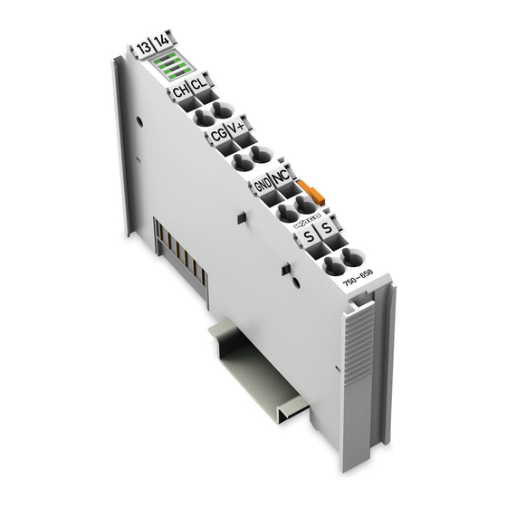
Device Description WAGO-I/O-SYSTEM 750 750-658 CAN Gateway View Figure 1: View Table 5: Legend for Figure “View” Pos. Description Details See Section Marking possibility with Mini- Status LEDs “Device Description” > “Display Elements” Data contacts “Device Description” > “Connectors” ®... -
Page 19: Connectors
WAGO-I/O-SYSTEM 750 Device Description 750-658 CAN Gateway Connectors 4.2.1 Data Contacts/Local Bus Communication between the fieldbus coupler/controller and the I/O modules as well as the system supply of the I/O modules is carried out via the local bus. It is comprised of 6 data contacts, which are available as self-cleaning gold spring contacts. -
Page 20: Power Jumper Contacts/Field Supply
The blade contacts are sharp-edged. Handle the I/O module carefully to prevent injury. Do not touch the blade contacts. The I/O module 750-658 has 2 self-cleaning power jumper contacts that supply and transmit power for the field side. The contacts on the left side of the I/O module are designed as blade contacts and those on the right side as spring contacts. - Page 21 WAGO-I/O-SYSTEM 750 Device Description 750-658 CAN Gateway Use supply modules for ground (earth)! The I/O module has no power jumper contacts for receiving and transmitting the earth potential. Use a supply module when an earth potential is needed for the subsequent I/O modules.
-
Page 22: Cage Clamp
Device Description WAGO-I/O-SYSTEM 750 750-658 CAN Gateway ® 4.2.3 CAGE CLAMP Connectors ® Figure 4: CAGE CLAMP Connectors ® Table 7: Legend for Figure “CAGE CLAMP Connectors“ Designation Connector Function CAN-H CAN high CAN-GND CAN ground Supply voltage 0 V... -
Page 23: Display Elements
WAGO-I/O-SYSTEM 750 Device Description 750-658 CAN Gateway Display Elements Figure 5: Display Elements Table 8: Legend for Figure “Display Elements” Designation State Function Error on the CAN bus. CAN bus not initialized. CAN status Green CAN bus properly initialized. CAN telegram could not be received. -
Page 24: Schematic Diagram
Device Description WAGO-I/O-SYSTEM 750 750-658 CAN Gateway Schematic Diagram Figure 6: Schematic Diagram Manual Version 1.2.1, valid from FW/HW-Version 01/01... -
Page 25: Technical Data
WAGO-I/O-SYSTEM 750 Device Description 750-658 CAN Gateway Technical Data 4.5.1 Device Data Table 9: Technical Data – Device Width 12 mm/0.472 in Height (from upper edge of DIN 35 rail) 64 mm Length 100 mm Weight Approx. 55 g Degree of protection... -
Page 26: Can Communication
Device Description WAGO-I/O-SYSTEM 750 750-658 CAN Gateway 4.5.3 CAN Communication Table 11: Technical Data – CAN Communication Baud rates CAN 10 kbit/s 20 kbit/s 50 kbit/s 125 kbit/s 250 kbit/s 500 kbit/s 800 kbit/s 1000 kbit/s Auto baud rate Diagnostic information... -
Page 27: Climatic Environmental Conditions
WAGO-I/O-SYSTEM 750 Device Description 750-658 CAN Gateway 4.5.5 Climatic Environmental Conditions Table 15: Technical Data – Climatic Environmental Conditions Surrounding air temperature, operation 0 °C … 55 °C Surrounding air temperature, storage −25 °C … +85 °C Operating altitude without temperature derating: 0 …... -
Page 28: Approvals
The following approvals have been granted to 750-658 I/O modules: Conformity Marking UL508 Korea Certification MSIP-REM-W43-MSM750 The following Ex approvals have been granted to 750-658 I/O modules: TÜV 14 ATEX 148929 X II 3 G Ex nA IIC T4 Gc IECEx TUN 14.0035 X Ex nA IIC T4 Gc ANSI/ISA 12.12.01... -
Page 29: Standards And Guidelines
WAGO-I/O-SYSTEM 750 Device Description 750-658 CAN Gateway Standards and Guidelines 750-658 I/O modules meet the following requirements on emission and immunity of interference: EMC CE-Immunity to interference EN 61000-6-2 EMC CE-Immunity to interference EN 61131-2 EMC CE-Emission of interference EN 61000-6-3 + A1... -
Page 30: Function Description
The data can be transferred by the "Mailbox 2.0" protocol among others. Use Mailbox 2.0! Use IEC-61131 compliant function blocks to use Mailbox 2.0. You can download them at www.wago.com. Figure 7: Functional Description 750-658 Operating Modes The I/O module can be operated in the following three modes: •... -
Page 31: Sniffer Mode
WAGO-I/O-SYSTEM 750 Function Description 750-658 CAN Gateway 5.1.1 Sniffer Mode In "Sniffer mode", the I/O module is a passive node in the bus network. That means that the transmitter is deactivated from the hardware side. In this operating mode telegrams can only be sent and not sent in principle. -
Page 32: Map Can Telegrams In Output Direction
Function Description WAGO-I/O-SYSTEM 750 750-658 CAN Gateway Once a CAN telegram is received, the bytes in question are updated in the process image of the input with the respective data. 5.1.3.2 Map CAN Telegrams in Output Direction CAN telegrams can also be mapped in the output direction. However, it is somewhat more complex because individual settings are required for each telegram before it can be sent. -
Page 33: 5.1.3.2.2 "Send On Request" Setting
WAGO-I/O-SYSTEM 750 Function Description 750-658 CAN Gateway "Remote Transmission Request" (RTR) Setting The "Remote Transmission Request" bit can used to set whether the mapped CAN output frame involves a so-called "remote request" or a data frame. "Data Length Code" (DLC) Setting The "Data Length Code"... -
Page 34: Access Can Telegrams Via The Mailbox
Function Description WAGO-I/O-SYSTEM 750 750-658 CAN Gateway 5.1.3.3 Access CAN Telegrams via the Mailbox CAN telegrams of a defined range can also be received and sent via the mailbox. The data format is identical to the data formats of the "Sniffer" and "Transparent"... -
Page 35: Filter Settings
WAGO-I/O-SYSTEM 750 Function Description 750-658 CAN Gateway Filter Settings With 6 configurable pass-through filters, the bandwidth of the CAN telegrams for the user transmitted to the controller can be limited to specific ranges. This saves resources on the control level and in the I/O module. -
Page 36: Process Image
Process Image WAGO-I/O-SYSTEM 750 750-658 CAN Gateway Process Image The first byte of the local bus process image is: • The control byte in the process output direction • The status byte in the process input direction The mailbox is static in the process image and is cross-faded when register communication is on. -
Page 37: Process Image In "Sniffer" Operating Mode
WAGO-I/O-SYSTEM 750 Process Image 750-658 CAN Gateway Process Image in "Sniffer" Operating Mode The CAN user data range on the process image is symmetrical for both data directions. Figure 10: Process Image in "Sniffer" Mode 6.1.1 Mailbox Modules with mailbox functionality have an acyclic communication channel (mailbox) in the process image. -
Page 38: Table 19: Structure Of Can Telegrams With The "2.0A Standard Frame" Setting
Process Image WAGO-I/O-SYSTEM 750 750-658 CAN Gateway If the "2.0A Standard Frame" is activated, CAN telegrams have the following structure: Table 19: Structure of CAN Telegrams with the "2.0A Standard Frame" Setting Byte Name Bits Identifier ID.10 ID.9 ID.8 ID.7 ID.6... -
Page 39: Process Image In "Transparent" Operating Mode
WAGO-I/O-SYSTEM 750 Process Image 750-658 CAN Gateway Process Image in "Transparent" Operating Mode The CAN user data range on the process image is symmetrical for both data directions. Figure 11: Process Image in the "Transparent" Operating Mode 6.2.1 Mailbox See section "Mailbox" in the "Sniffer" operating mode. -
Page 40: Process Image In The "Mapped" Operating Mode
Process Image WAGO-I/O-SYSTEM 750 750-658 CAN Gateway Process Image in the "Mapped" Operating Mode Figure 12: Process Image in the "Mapped" Operating Mode 6.3.1 Mailbox See section "Mailbox" in the "Sniffer" operating mode. 6.3.2 Toggle Byte The toggle byte is a fixed component of the "Mapped" operating mode (see respective section). -
Page 41: Mounting
Don't forget the bus end module! Always plug a bus end module (750-600) onto the end of the fieldbus node! You must always use a bus end module at all fieldbus nodes with WAGO-I/O- SYSTEM 750 fieldbus couplers or controllers to guarantee proper data transfer. -
Page 42: Inserting And Removing Devices
Mounting WAGO-I/O-SYSTEM 750 750-658 CAN Gateway Inserting and Removing Devices Do not work when devices are energized! High voltage can cause electric shock or burns. Switch off all power to the device prior to performing any installation, repair or maintenance work. -
Page 43: Removing The I/O Module
WAGO-I/O-SYSTEM 750 Mounting 750-658 CAN Gateway 7.2.2 Removing the I/O Module Remove the I/O module from the assembly by pulling the release tab. Figure 15: Removing the I/O Module (Example) Electrical connections for data or power jumper contacts are disconnected when removing the I/O module. -
Page 44: Connect Devices
Only one conductor may be connected to each CAGE CLAMP Do not connect more than one conductor at one single connection! If more than one conductor must be routed to one connection, these must be connected in an up-circuit wiring assembly, for example using WAGO feed- through terminals. ®... -
Page 45: Connect Can Bus
WAGO-I/O-SYSTEM 750 Connect Devices 750-658 CAN Gateway Connect CAN Bus Connect a terminating resistor of 120 Ω parallel to the "CAN H" and "CAN L" lines if the I/O module is the last node in the CAN network. Manual Version 1.2.1, valid from FW/HW-Version 01/01... -
Page 46: Configuration And Parameterization
Configuration software using device description files (e.g. PROFIBUS- GSD), see appendix, section "Configuration Using PROFIBUS GSD" Configuration and parameterization via WAGO-I/O-CHECK and WAGO-I/O-PRO make use of acyclic communication via the Mailbox and register communication. For access via the Mailbox, a parameter access service is provided by the I/O module. -
Page 47: Configuration And Parameterization With Wago-I/O-Check
Diagnostics of the I/O module WAGO-I/O-CHECK You can obtain the WAGO-I/O-CHECK software on a CD under Item No. 759-302. This CD contains all the application program files and an explanation. You can find a description at the internet page at http://www.wago.com... -
Page 48: Configuration Dialog
Configuration and Parameterization WAGO-I/O-SYSTEM 750 750-658 CAN Gateway 9.1.1 Configuration Dialog The configuration dialog is divided into the following areas: Figure 18: Configuration Dialog of the I/O Module Toolbar Function area Diagnosis area These areas will be explained in more detail in the following sections. -
Page 49: Table 22: Buttons On The Main Menu
WAGO-I/O-SYSTEM 750 Configuration and Parameterization 750-658 CAN Gateway Table 22: Buttons on the Main Menu Button Function Description [Disconnect] Interrupts an existing connection to the I/O module [Sniffer Mode] Opens the function area for the "Sniffer" operating mode and puts the I/O module in this operating mode. -
Page 50: Figure 20: Buttons In The Application Menu
Configuration and Parameterization WAGO-I/O-SYSTEM 750 750-658 CAN Gateway Table 22: Buttons on the Main Menu Button Function Description [PII] Opens the specific "PII" function area in the "Mapped" operating mode. [PIO] Opens the specific "PIO" function area in the "Mapped" operating mode. -
Page 51: Function Area
WAGO-I/O-SYSTEM 750 Configuration and Parameterization 750-658 CAN Gateway Table 23: Buttons in the Application Menu Button Function Description Opens an existing parameter file [Open] (see section "Load Parameters into the Application"). Saves all read parameters in a parameter file. WAGO-I/O-CHECK... -
Page 52: Load Parameters Into The Application
9.1.2 Load Parameters into the Application To load parameters into the application: Click the [Open] button. WAGO-I/O-CHECK displays the default dialog for opening files. Select a parameter file. In the "Select data" dialog, select the parameters to be loaded from the file. -
Page 53: Table 24: Parameters In The "Select Data" Dialog
WAGO-I/O-SYSTEM 750 Configuration and Parameterization 750-658 CAN Gateway Parameters in the “Select Data” Dialog Table 24: Parameters in the “Select Data” Dialog Check Box Description Configuration If the checkbox is selected, the selected parameters are automatically Operating mode written to the I/O module after loading. -
Page 54: Configuration" Dialog
"WARNING" error type: A yellow LED lights up. • "NOTIFICATION" error type: A green LED lights up. A message is also generated in WAGO-I/O-CHECK depending on the error type: • "Singleshot" error type: A message is sent if an error occurs. -
Page 55: Set Mailbox Length
WAGO-I/O-SYSTEM 750 Configuration and Parameterization 750-658 CAN Gateway The diagnostics and their meaning can be found in the table “Diagnostics“ in Section “Diagnostics“. 9.1.3.2 Set Mailbox Length Specify how large the mailbox should be (in bytes). Enter the corresponding value in the "Length" input field. -
Page 56: Setting The Process Image Size
Configuration and Parameterization WAGO-I/O-SYSTEM 750 750-658 CAN Gateway 9.1.3.3 Setting the Process Image Size Set the process image size. The following settings are possible: 8 bytes, 12 bytes, 16 bytes, 20 bytes, 24 bytes, 32 bytes, 40 bytes and 48 bytes. -
Page 57: Function Area In The "Sniffer Mode
WAGO-I/O-SYSTEM 750 Configuration and Parameterization 750-658 CAN Gateway 9.1.4 Function Area in the "Sniffer Mode" All CAN telegrams received are listed in the "Receive" dialog. Figure 25: Function Area in the "Sniffer Mode" The following interaction options are available: •... -
Page 58: Function Area In The "Transparent Mode
Configuration and Parameterization WAGO-I/O-SYSTEM 750 750-658 CAN Gateway 9.1.5 Function Area in the "Transparent Mode" All CAN telegrams received are listed in the "Received" dialog. Figure 26: Function Area in the "Transparent Mode" The following interaction options are available: [Delete] button: Deletes the existing list. - Page 59 WAGO-I/O-SYSTEM 750 Configuration and Parameterization 750-658 CAN Gateway • DLC input field: The user data length of the CAN telegram to send can be specified here (value range 0 - 8). • Data input field: The user data of the CAN telegram to be sent can be entered here in hexadecimal format.
-
Page 60: Function Area In The "Mapped Mode
Configuration and Parameterization WAGO-I/O-SYSTEM 750 750-658 CAN Gateway 9.1.6 Function Area in the "Mapped Mode" In the "View" menu item, the "PII" (process image of the input) and "PIO" (process image of the output) views can be selected. The function area changes according to the selected setting. -
Page 61: Figure 28: "Add Mapping Rule" Dialog
WAGO-I/O-SYSTEM 750 Configuration and Parameterization 750-658 CAN Gateway [Add] button: Adds the created mapping rule to the list of mapping rules and closes the dialog. [Cancel] button: Cancels the process and closes the dialog. Figure 28: "Add mapping rule" Dialog •... -
Page 62: Pio" View
Configuration and Parameterization WAGO-I/O-SYSTEM 750 750-658 CAN Gateway 9.1.6.2 "PIO" View There are two different display windows in the function area: • The process image-oriented display (left) • The CAN display (right) These show the current mapping rules for the process image of the output. -
Page 63: Figure 31: "Add Mapping Rule" Dialog
WAGO-I/O-SYSTEM 750 Configuration and Parameterization 750-658 CAN Gateway [Fix] button: If the button is active, the entered value is copied to the user data byte of the CAN telegram as a fixed value. IDE checkbox: If the checkbox is selected, CAN telegrams of type "2.0B Extended"... -
Page 64: Figure 32: "Change Mapping Rule" Dialog
Configuration and Parameterization WAGO-I/O-SYSTEM 750 750-658 CAN Gateway • [Change] button: Opens the "Change mapping rule" dialog to go to the configuration dialog. All values except the CAN ID can be edited. The interaction options are identical to those in the "Add mapping rule" dialog. -
Page 65: Can Parameter" Dialog
WAGO-I/O-SYSTEM 750 Configuration and Parameterization 750-658 CAN Gateway 9.1.7 "CAN Parameter" Dialog You can set parameters across operating modes in the "CAN Parameters" dialog. 9.1.7.1 Select CAN Data Format Click in the "Data Format" selection box to select a data format. You can select the following formats: •... -
Page 66: Set Can Baud Rate
Configuration and Parameterization WAGO-I/O-SYSTEM 750 750-658 CAN Gateway 9.1.7.2 Set CAN Baud Rate Click in the "Baud Rate" selection box to select a baud rate. The following settings are possible: 10 kBit/s, 20 kBit/s, 50 kBit/s, 125 kBit/s, 250 kBit/s, 500 kBit/s, 800 kBit/s, 1000 kBit/s and "Auto-Baudrate". -
Page 67: Filter" Dialog
WAGO-I/O-SYSTEM 750 Configuration and Parameterization 750-658 CAN Gateway 9.1.8 "Filter" Dialog With 6 configurable pass-through filters, the bandwidth of received CAN telegrams for the user can be limited to specific ranges. This saves resources on the control level and in the I/O module. -
Page 68: Figure 36: Send Can Telegrams Via The Mailbox
Configuration and Parameterization WAGO-I/O-SYSTEM 750 750-658 CAN Gateway Do not select the "Overwrite" setting for protocol data! The "Overwrite" setting should not be selected when protocol data is transmitted. The protocol data may be unusable because all data of a CAN ID is required in general. -
Page 69: Configuration And Parameterization With E!Cockpit
Configuration and Parameterization with e!COCKPIT Configuration and parameterization differ only slightly in in e!COCKPIT and WAGO-I/O-CHECK. For that reason, only the deviations are explained that apply to the e!COCKPIT software. Configuration and Parameterization in the e!COCKPIT Software! General information on configuration and parameterization in the e!COCKPIT software is available in the respective manual! This manual has item No. -
Page 70: Startup With Wago-I/O-Pro
The WAGO-I/O-PRO library "WagoLib_CAN_Gateway.lib" provides the option to start up the I/O module using the corresponding function blocks. Library cannot be used to set the process image size! The WAGO-I/O-PRO library "WagoLib_CAN_Gateway.lib" is not used to set the process image size. Additional information The WAGO-I/O-PRO library "WagoLib_CAN_Gateway.lib"... -
Page 71: Diagnostics
WAGO-I/O-SYSTEM 750 Diagnostics 750-658 CAN Gateway Diagnostics The following diagnostics are output via mailbox and can also be viewed via the respective user interface: Table 25: Diagnostics Error code Diagnostics Explanation 3E8 (1000) CAN Stuff Error There is a single error on the CAN bus. - Page 72 Diagnostics WAGO-I/O-SYSTEM 750 750-658 CAN Gateway Table 25: Diagnostics Error code Diagnostics Explanation ExtRegCom Rsp Advanced register communication: 7D4 (2004) Access Denied access denied ExtRegCom Table Advanced register communication: 7D5 (2005) Read Only Table is read-only. ExtRegCom Data Advanced register communication:...
-
Page 73: Use In Hazardous Environments
Use in Hazardous Environments 750-658 CAN Gateway Use in Hazardous Environments The WAGO-I/O-SYSTEM 750 (electrical equipment) is designed for use in Zone 2 hazardous areas and shall be used in accordance with the marking and installation regulations. The following sections include both the general identification of components (devices) and the installation regulations to be observed. -
Page 74: Marking Configuration Examples
Use in Hazardous Environments WAGO-I/O-SYSTEM 750 750-658 CAN Gateway 11.1 Marking Configuration Examples 11.1.1 Marking for Europe According to ATEX and IECEx Figure 38: Marking Example According to ATEX and IECEx Figure 39: Text Detail – Marking Example According to ATEX and IECEx Manual Version 1.2.1, valid from FW/HW-Version 01/01... -
Page 75: Table 26: Description Of Marking Example According To Atex And Iecex
WAGO-I/O-SYSTEM 750 Use in Hazardous Environments 750-658 CAN Gateway Table 26: Description of Marking Example According to ATEX and IECEx Marking Description TUEV 07 ATEX 554086 X Approving authority resp. certificate numbers IECEx TUN 09.0001 X Dust Equipment group: All except mining... -
Page 76: Figure 40: Marking Example For Approved Ex I I/O Module According To
Use in Hazardous Environments WAGO-I/O-SYSTEM 750 750-658 CAN Gateway Figure 40: Marking Example for Approved Ex i I/O Module According to ATEX and IECEx Figure 41: Text Detail – Marking Example for Approved Ex i I/O Module According to ATEX and... -
Page 77: Table 27: Description Of Marking Example For Approved Ex I I/O Module According To Atex And Iecex
WAGO-I/O-SYSTEM 750 Use in Hazardous Environments 750-658 CAN Gateway Table 27: Description of Marking Example for Approved Ex i I/O Module According to ATEX and IECEx Marking Description TUEV 12 ATEX 106032 X Approving authority resp. certificate numbers IECEx TUN 12 0039 X... -
Page 78: Marking For The United States Of America (Nec) And Canada (Cec)
Use in Hazardous Environments WAGO-I/O-SYSTEM 750 750-658 CAN Gateway 11.1.2 Marking for the United States of America (NEC) and Canada (CEC) Figure 42: Marking Example According to NEC Figure 43: Text Detail – Marking Example According to NEC 500 Table 28: Description of Marking Example According to NEC 500... -
Page 79: Figure 44: Text Detail - Marking Example For Approved Ex I I/O Module
WAGO-I/O-SYSTEM 750 Use in Hazardous Environments 750-658 CAN Gateway Figure 44: Text Detail – Marking Example for Approved Ex i I/O Module According to NEC 505 Table 29: Description of Marking Example for Approved Ex i I/O Module According to NEC 505... -
Page 80: Figure 46: Text Detail - Marking Example For Approved Ex I I/O Modules
Use in Hazardous Environments WAGO-I/O-SYSTEM 750 750-658 CAN Gateway Figure 46: Text Detail – Marking Example for Approved Ex i I/O Modules According to CEC 18 attachment J Table 31: Description of Marking Example for Approved Ex i I/O Modules According to CEC 18... -
Page 81: Installation Regulations
WAGO-I/O-SYSTEM 750 Use in Hazardous Environments 750-658 CAN Gateway 11.2 Installation Regulations For the installation and operation of electrical equipment in hazardous areas, the valid national and international rules and regulations which are applicable at the installation location must be carefully followed. - Page 82 Use in Hazardous Environments WAGO-I/O-SYSTEM 750 750-658 CAN Gateway Explosive atmosphere occurring simultaneously with assembly, installation or repair work must be ruled out. Among other things, these include the following activities • Insertion and removal of components • Connecting or disconnecting from fieldbus, antenna, D-Sub, ETHERNET or...
-
Page 83: Special Notes Regarding Ansi/Isa Ex
WAGO-I/O-SYSTEM 750 Use in Hazardous Environments 750-658 CAN Gateway 11.2.2 Special Notes Regarding ANSI/ISA Ex For ANSI/ISA Ex acc. to UL File E198726, the following additional requirements apply: • Use in Class I, Division 2, Group A, B, C, D or non-hazardous areas only •... -
Page 84: Appendix
Transmit data 2.0) Figure 47: Communication via Mailbox 2.0 Example: A sender wants to transfer 10 bytes (the character string "Hello Wago") to a receiver via a 4-byte wide channel. 12.1.1 Message The Mailbox 2.0 method packages the data in messages. A message contains a header and user data. -
Page 85: Transmission Channel
WAGO-I/O-SYSTEM 750 Appendix 750-658 CAN Gateway Structure of the simple header: Table 32: Structure of the Simple Header Simple header Bit 7 Bit 6 Bit 5 Bit 4 Bit 3 Bit 2 Bit 1 Bit 0 Length Data element length max. 127... -
Page 86: The Handshake Byte
Appendix WAGO-I/O-SYSTEM 750 750-658 CAN Gateway 12.1.2.1 The Handshake Byte In general, a distinction is made between Control(C) and Toggle(T) mode (bit 7). The Control mode is used to synchronize the subscribers. The Toggle mode is used to exchange data. -
Page 87: Communication Phases
WAGO-I/O-SYSTEM 750 Appendix 750-658 CAN Gateway 12.1.3 Communication Phases The Mailbox 2.0 mechanism defines two communication phases: • Synchronization • Data exchange Only after successful synchronization from sender to receiver the actual user data can be exchanged. 12.1.3.1 Synchronization In the synchronization phase, the handshake byte is used in Control mode. -
Page 88: 12.1.3.1.2 Acknowledgement
Appendix WAGO-I/O-SYSTEM 750 750-658 CAN Gateway 12.1.3.1.2 Acknowledgement The following acknowledgements are defined: Table 36: Acknowledgement Value Explanation Description INVALID Signals that the receiver has not started operations again after a reset. HOLD ACKNOWLEDGE Signal or confirmation that the channel is ready, but data is not currently being transferred (e.g. -
Page 89: 12.1.3.1.4 Finite Automation
WAGO-I/O-SYSTEM 750 Appendix 750-658 CAN Gateway 12.1.3.1.4 Finite Automation Synchronization follows the chart below. Figure 49: Finite Automation Manual Version 1.2.1, valid from FW/HW-Version 01/01... -
Page 90: Data Exchange
Appendix WAGO-I/O-SYSTEM 750 750-658 CAN Gateway 12.1.3.2 Data Exchange In the data exchange phase, the handshake byte is used in Toggle mode. Because a message is normally larger than the data part of the transmission channel, the message must be transferred in several cycles (fragmentation). -
Page 91: 12.1.3.2.1 Example
WAGO-I/O-SYSTEM 750 Appendix 750-658 CAN Gateway 12.1.3.2.1 Example The following example shows use of the transmission channel during a send operation (no full-duplex transmission): Figure 50: Example of Send Operation Manual Version 1.2.1, valid from FW/HW-Version 01/01... -
Page 92: Protocols Supported By Mailbox 2.0
Appendix WAGO-I/O-SYSTEM 750 750-658 CAN Gateway 12.2 Protocols Supported by Mailbox 2.0 Messages can be exchanged between different devices using the Mailbox 2.0 transfer procedure. Messages that are exchanged can be read by the communication partner only when they are structured in line with a known protocol. -
Page 93: Protocol 0X81 (Diagnostics)
WAGO-I/O-SYSTEM 750 Appendix 750-658 CAN Gateway Table 41: Protocol 0x80, PDU Structure Service PDU Structure of PDU (Bytes 0 … 5) Request: Read 0x00 0x01 Request: Write 0x00 0x04 Request: Save 0x00 0x09 Request: Restore 0x00 0x0c Request: Set password... -
Page 94: Table 43: Protocol 0X81, Description Of Services
Appendix WAGO-I/O-SYSTEM 750 750-658 CAN Gateway Table 43: Protocol 0x81, Description of Services Service Description Diagnostics Transmission of a diagnosis as a message. The table below shows the structure of PDUs for this protocol: Table 44: Protocol 0x81, PDU Structure Service PDU Structure of PDU (Bytes 0 …... -
Page 95: Overview Of Parameters
WAGO-I/O-SYSTEM 750 Appendix 750-658 CAN Gateway 12.3 Overview of Parameters The structure and encoding for the parameters stored in the I/O module are described below. These parameters are organized as registers. A data volume of one word can be stored per register. Several registers are combined into a table, as some parameters require that a larger data volume be stored, or are closely tied to other parameters. -
Page 96: Tables 100
Appendix WAGO-I/O-SYSTEM 750 750-658 CAN Gateway Table 47: Expanded Configuration, Tables 50 … 55, Register 4: FILTER ENABLE Description Possible values Explanation FILTER ENABLE 0x0000 Filter deactivated 0x0001 Filter activated Register 5 saves the storage handling process. Table 48: Expanded Configuration, Tables 50 … 55, Register 5: Filter FIFO Handling... -
Page 97: Table 50: Expanded Configuration, Basic Structure Of Tables 100
WAGO-I/O-SYSTEM 750 Appendix 750-658 CAN Gateway Table 50: Expanded Configuration, Basic Structure of Tables 100 … 144 Description Acceptable Default value range standard value CAN ID MSW 0x0000 … 0xFFFF 0xFFFF CAN ID LSW 0x0000 … 0xFFFF 0xFFFF IDE_RTR_DLC_SEN 0x0000...0x1FFF... -
Page 98: Table 52: Expanded Configuration, Tables 100
Appendix WAGO-I/O-SYSTEM 750 750-658 CAN Gateway Table 52: Expanded Configuration, Tables 100 … 144, Register 2: IDE_RTR_DLC_SENDGROUP_SOC Register Value range / Description bits Possible values 2.0 … 2.3 CAN telegram not assigned to a transmission group. 0x1, 0x8, CAN telegram assigned to transmission group 1 …... -
Page 99: Tables 200
WAGO-I/O-SYSTEM 750 Appendix 750-658 CAN Gateway Table 54: Expanded Configuration, Tables 100 … 144, Register 4: CAN_PAYLOAD_DATA_1_0 Register Value range / Description bits Possible values 4.0 – 4.7 [0x00...0xFF] When CAN payload data byte 0 is a fixed value: Value of payload data byte 0... -
Page 100: Table 56: Expanded Configuration, Basic Structure Of Tables 200
100 Appendix WAGO-I/O-SYSTEM 750 750-658 CAN Gateway Table 56: Expanded Configuration, Basic Structure of Tables 200 … 244 Description Acceptable Default value range standard value CAN ID MSW 0x0000 … 0xFFFF 0xFFFF CAN ID LSW 0x0000 … 0xFFFF 0xFFFF COPY_TO_PD_IN 0x0000...0x00FF... -
Page 101: Table 58: Expanded Configuration, Register 2: Copy_To_Pd_In
WAGO-I/O-SYSTEM 750 Appendix 101 750-658 CAN Gateway Table 58: Expanded Configuration, Register 2: COPY_TO_PD_IN Register Value range / Description bits Possible values Refreshing of a byte in the process image (input) using the value for CAN payload data byte 0 activated. -
Page 102: Register Communication
102 Appendix WAGO-I/O-SYSTEM 750 750-658 CAN Gateway 12.4 Register Communication Register communication (control byte, bit 7 = 1) can be used to access an internal data structure of the I/O module consisting of 64 registers each with 2 bytes (data type WORD). No automated handshake mechanism is used. That... -
Page 103: Control/Status Byte
WAGO-I/O-SYSTEM 750 Appendix 103 750-658 CAN Gateway 12.4.1 Control/Status Byte The control byte has the following structure: Table 60: Control Byte Control Byte Bit 7 Bit 6 Bit 5 Bit 4 Bit 3 Bit 2 Bit 1 Bit 0 0 = Read Register... -
Page 104: Register Overview
Hardware version 17-26 --- 0x0000 Reserved Var. Reserved EEPROM ro 0x0000 WAGO order number, digits 10 - 12 EEPROM ro 0x0000 WAGO order number, digits 7 - 9 EEPROM ro 0x19AA WAGO order number, digits 4 - 6 Var. Code word EEPROM r/w Var. -
Page 105: List Of Figures
Connectors ..............22 Figure 5: Display Elements .................. 23 Figure 6: Schematic Diagram ................24 Figure 7: Functional Description 750-658 ............30 Figure 8: Map CAN Telegrams in Input Direction ..........31 Figure 9: Map CAN Telegrams in Output Direction ..........32 Figure 10: Process Image in "Sniffer"... - Page 106 106 List of Figures WAGO-I/O-SYSTEM 750 750-658 CAN Gateway Figure 45: Text Detail – Marking Example for Approved Ex i I/O Module According to NEC 506 ................79 Figure 46: Text Detail – Marking Example for Approved Ex i I/O Modules According to CEC 18 attachment J ............
-
Page 107: List Of Tables
List of Tables Table 1: Number Notation ..................9 Table 2: Font Conventions ..................9 Table 3: 750-658 Compatibility List – Fieldbus Couplers/Controllers ....16 Table 4: 750-658 Compatibility List – IPC ............17 Table 5: Legend for Figure “View” ............... 18 Table 6: Legend for Figure “Power Jumper Contacts”... - Page 108 108 List of Tables WAGO-I/O-SYSTEM 750 750-658 CAN Gateway Table 42: Protocol 0x80, Structure of PDUs, Legend .......... 93 Table 43: Protocol 0x81, Description of Services ..........94 Table 44: Protocol 0x81, PDU Structure .............. 94 Table 45: Protocol 0x81, Structure of PDUs, Legend .......... 94 Table 46: Expanded Configuration, Tables 50 …...
- Page 109 WAGO-I/O-SYSTEM 750 750-658 CAN Gateway Manual Version 1.2.1, valid from FW/HW-Version 01/01...
- Page 110 WAGO Kontakttechnik GmbH & Co. KG Postfach 2880 • D - 32385 Minden Hansastraße 27 • D - 32423 Minden Phone: +49 571 887 – 0 Fax: +49 571 887 – 844169 E-Mail: info@wago.com Internet: www.wago.com...
Need help?
Do you have a question about the 750-658 and is the answer not in the manual?
Questions and answers