
Related Manuals for WAGO 758-916


Summary of Contents for WAGO 758-916
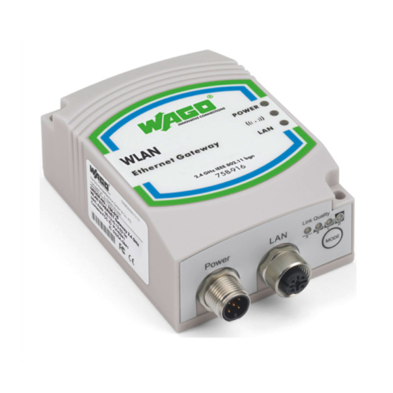
- Page 1 Manual WAGO-I/O-SYSTEM 758 WLAN ETHERNET Gateway 2.4 GHz 758-916 Version 1.0.1, applicable from HW/SW Version 01/01...
- Page 2 WAGO-I/O-SYSTEM 758 758-916 WLAN ETHERNET Gateway 2.4 GHz © 2014 by WAGO Kontakttechnik GmbH & Co. KG All rights reserved. WAGO Kontakttechnik GmbH & Co. KG Hansastraße 27 D-32423 Minden Phone: +49 (0) 571/8 87 – 0 Fax: +49 (0) 571/8 87 – 1 69 E-Mail: info@wago.com...
-
Page 3: Table Of Contents
WAGO-I/O-SYSTEM 758 Table of Contents 758-916 WLAN ETHERNET Gateway 2.4 GHz Table of Contents Notes about this Documentation ..............5 Validity of this Documentation ..............5 Revision History ..................5 Copyright ....................5 Symbols ..................... 6 Number Notation ..................8 Font Conventions .................. - Page 4 Table of Contents WAGO-I/O-SYSTEM 758 758-916 WLAN ETHERNET Gateway 2.4 GHz Configuration Using the Mode Membrane Button ......... 33 7.2.1 Selection and Activation of an Autoconfiguration Procedure .... 33 7.2.2 Overview of Autoconfiguration Procedures ........36 Configuration Using the External Trigger Input ........38 Configuration using the Web-based Management System (WBM) ..
-
Page 5: Notes About This Documentation
Manual by third parties that violate pertinent copyright provisions is prohibited. Reproduction, translation, electronic and phototechnical filing/archiving (e.g., photocopying) as well as any amendments require the written consent of WAGO Kontakttechnik GmbH & Co. KG, Minden, Germany. Non-observance will involve the right to assert damage claims. Manual... -
Page 6: Symbols
Notes about this Documentation WAGO-I/O-SYSTEM 758 758-916 WLAN ETHERNET Gateway 2.4 GHz Symbols Personal Injury! Indicates a high-risk, imminently hazardous situation which, if not avoided, will result in death or serious injury. Personal Injury Caused by Electric Current! Indicates a high-risk, imminently hazardous situation which, if not avoided, will result in death or serious injury. - Page 7 WAGO-I/O-SYSTEM 758 Notes about this Documentation 758-916 WLAN ETHERNET Gateway 2.4 GHz Additional Information: Refers to additional information which is not an integral part of this documentation (e.g., the Internet). Manual Version 1.0.1, applicable from HW/SW Version 01/01...
-
Page 8: Number Notation
Notes about this Documentation WAGO-I/O-SYSTEM 758 758-916 WLAN ETHERNET Gateway 2.4 GHz Number Notation Table 2: Number notation Number code Example Note Decimal Normal notation Hexadecimal 0x64 C notation Binary '100' In quotation marks, nibble separated with '0110.0100' dots (.) -
Page 9: Important Notes
2.1.1 Subject to Changes WAGO Kontakttechnik GmbH & Co. KG reserves the right to provide for any alterations or modifications that serve to increase the efficiency of technical progress. WAGO Kontakttechnik GmbH & Co. KG owns all rights arising from the granting of patents or from the legal protection of utility patents. -
Page 10: Special Use Conditions For Ethernet Devices
The components to be supplied Ex Works, are equipped with hardware and software configurations, which meet the individual application requirements. WAGO Kontakttechnik GmbH & Co. KG will be exempted from any liability in case of changes in hardware or software as well as to non-compliant usage of components. -
Page 11: Safety Advice (Precautions)
WAGO-I/O-SYSTEM 758 Important Notes 758-916 WLAN ETHERNET Gateway 2.4 GHz Safety Advice (Precautions) For installing and operating purposes of the relevant device to your system the following safety precautions shall be observed: Always use voltage sources with current limitation/safety extra-low voltage! Only use power supply sources based on IEC/EN60950 Section 2.5 “Power... - Page 12 Important Notes WAGO-I/O-SYSTEM 758 758-916 WLAN ETHERNET Gateway 2.4 GHz Protect the components against materials having seeping and insulating properties! The components are not resistant to materials having seeping and insulating properties such as: aerosols, silicones and triglycerides (found in some hand creams).
-
Page 13: Device Description
758-916 WLAN ETHERNET Gateway 2.4 GHz Device Description General Description As a wireless ETHERNET gateway (WEG), the 758-916 device makes it possible to integrate conventional ETHERNET devices in a wireless network. For this purpose, the device has a wired ETHERNET interface and another interface for radio communication. -
Page 14: Figure 2: Infrastructure Mode
Device Description WAGO-I/O-SYSTEM 758 758-916 WLAN ETHERNET Gateway 2.4 GHz Figure 2: Infrastructure mode In infrastructure mode, a distinction is made between two roles for devices in the network. One of the WLAN devices must act as an access point and centrally manage the network while all other WLAN devices act as clients. -
Page 15: Lan Connection Types
WAGO-I/O-SYSTEM 758 Device Description 758-916 WLAN ETHERNET Gateway 2.4 GHz The WEG can establish a connection with WLAN networks of both operating modes, but cannot function as an access point itself. If an access point is available and the WEGs can be configured via Web-based Management, the preferred method of operation for the WLAN is in infrastructure mode. -
Page 16: View
Device Description WAGO-I/O-SYSTEM 758 758-916 WLAN ETHERNET Gateway 2.4 GHz View Figure 4: View Table 4: Legend for the “View” figure No. Description Details see Section: Status and diagnosis LEDs (front) “Display Elements” Internal circular polarized directional antenna 5 dB “Connectors”... -
Page 17: Labeling
WAGO-I/O-SYSTEM 758 Device Description 758-916 WLAN ETHERNET Gateway 2.4 GHz Labeling The status indicators for (POWER, ( ), LAN) are marked on the front of the device. Figure 5: Marking on front of device The connections (Power, LAN), link quality and configuration button (Mode) are marked on the bottom of the device. -
Page 18: Connectors
Device Description WAGO-I/O-SYSTEM 758 758-916 WLAN ETHERNET Gateway 2.4 GHz Connectors The device is equipped with two connections at the bottom: Figure 8: Connections at bottom of device Table 5: Legend for the “Connections at bottom of device” figure No. Description Power supply and trigger input (“Power”) -
Page 19: Antenna
WAGO-I/O-SYSTEM 758 Device Description 758-916 WLAN ETHERNET Gateway 2.4 GHz 3.4.3 Antenna The device is equipped with an internal antenna. Good reception conditions exist when the front of the device is oriented centered to the remote device with which the radio link is to be established. -
Page 20: Figure 10: Antenna Diagram 2.45 Ghz - Longitudinal Axis
Device Description WAGO-I/O-SYSTEM 758 758-916 WLAN ETHERNET Gateway 2.4 GHz Figure 10: Antenna diagram 2.45 GHz – longitudinal axis The diagram above illustrates the two-dimensional top view of the electro- magnetic field of the antenna, with the antenna being the center point. At a beam angle of around 60°... -
Page 21: Display Elements
WAGO-I/O-SYSTEM 758 Device Description 758-916 WLAN ETHERNET Gateway 2.4 GHz Display Elements The current device status is indicated by the three LEDs on the front of the WEG. Four other LEDs at the bottom of the device indicate the link quality, or the selected autoconfiguration procedure. - Page 22 Device Description WAGO-I/O-SYSTEM 758 758-916 WLAN ETHERNET Gateway 2.4 GHz Display of the link quality in conjunction with access point only! LEDs A to D are only available for visualization of the link quality when the WEG is connected to an access point (infrastructure mode). In an ad-hoc network, this status indication is not available.
-
Page 23: Operating Elements
WAGO-I/O-SYSTEM 758 Device Description 758-916 WLAN ETHERNET Gateway 2.4 GHz Operating Elements The “Mode” membrane button is located at the bottom of the device. This button is used to initiate certain autoconfiguration procedures. LEDs A to D indicate which procedure is active. For more information about this refer to the Section “Configuration using the Mode membrane button”. -
Page 24: Technical Data
Device Description WAGO-I/O-SYSTEM 758 758-916 WLAN ETHERNET Gateway 2.4 GHz Technical Data 3.7.1 General Device Data Table 9: Technical Data – General Device Data Function Wireless ETHERNET Gateway (WEG) Dimensions (mm) 66 x 91 x 36 W x H x D... -
Page 25: Ethernet Interface
WAGO-I/O-SYSTEM 758 Device Description 758-916 WLAN ETHERNET Gateway 2.4 GHz 3.7.2 ETHERNET Interface Table 10: Technical Data – ETHERNET Interface Number of inputs Medium Via M12, twisted pair wire, wire cross section 0.14 mm² ... 0.22 mm² Transmission rate 10/100 MBit/s, Autonegotiation Default IP address 192.168.1.99... -
Page 26: Approvals
Device Description WAGO-I/O-SYSTEM 758 758-916 WLAN ETHERNET Gateway 2.4 GHz Approvals Conformity Marking IC „Industry Canada“ IC: 5325A-0941 FCC “Federal Communications Commission” FCC ID: PVH0941 / CFR 47 Part 15, ETS 300328 This device complies with Part 15 of the FCC Rules. Operation is subject to the following two conditions: (1) this device may not cause harmful interference, and (2) this device must accept any interference received, including interference that may cause undesired operation. -
Page 27: Mounting
WAGO-I/O-SYSTEM 758 Mounting 758-916 WLAN ETHERNET Gateway 2.4 GHz Mounting Selecting the Installation Location In order to use all the functions of the WEG, a radio link must be established to a device having similar functions, for example a second WEG of the same type. If... -
Page 28: Table 13: Selection Of Installation Location
Mounting WAGO-I/O-SYSTEM 758 758-916 WLAN ETHERNET Gateway 2.4 GHz Table 13: Selection of Installation Location Ambient Conditions, Installation Location Radio link possible? Distance between devices is more than 400 m. Line-of-sight link between devices that are about 200 m apart. Devices have been optimally installed and configured. -
Page 29: Fixing
WAGO-I/O-SYSTEM 758 Mounting 758-916 WLAN ETHERNET Gateway 2.4 GHz Fixing Always maintain a minimum distance of 50 cm between two WEGs! Always maintain a distance of at least 50 cm between WEGs when installing them. Radio link quality can be degraded on failure to maintain this distance. -
Page 30: Connect Devices
Always ensure that these cables have been laid properly before connecting the device to the network. Use a suitable cable, such as WAGO Item 756-1203/060-050, to connect the WEG to your network or ETHERNET terminal. Use a suitable cable, such as WAGO Item 756-3101/040-020, to connect the WEG to the external power supply unit. -
Page 31: Commissioning
WAGO-I/O-SYSTEM 758 Commissioning 758-916 WLAN ETHERNET Gateway 2.4 GHz Commissioning The device is not equipped with a power switch, meaning it is put into operation simply by applying power. Use the correct supply voltage! The output of the power supply unit must provide 24 VDC with a maximum current flow of 200 mA. -
Page 32: Configuration
Configuration WAGO-I/O-SYSTEM 758 758-916 WLAN ETHERNET Gateway 2.4 GHz Configuration After you have connected the WEG you can configure it in one of two ways: using the Mode membrane button and by activating certain modes • by making settings via the Web-based Management System (WBM) •... -
Page 33: Configuration Using The Mode Membrane Button
WAGO-I/O-SYSTEM 758 Configuration 758-916 WLAN ETHERNET Gateway 2.4 GHz Configuration Using the Mode Membrane Button The quickest and easiest method for configuring the device is using the Mode membrane button located at the bottom of the device. LEDs A to D indicate the status during configuration, based on the active operating mode. - Page 34 Configuration WAGO-I/O-SYSTEM 758 758-916 WLAN ETHERNET Gateway 2.4 GHz Configuration is halted if the Mode membrane button is not pressed for 20 s! The mode “Configuration selection” is de-activated automatically if you do not press the Mode membrane button for selecting the autoconfiguration procedure.
-
Page 35: Figure 17: Flow Chart
WAGO-I/O-SYSTEM 758 Configuration 758-916 WLAN ETHERNET Gateway 2.4 GHz Figure 17: Flow chart Enable de-activated WBM using the Mode membrane button! If autoconfiguration is conducted with PROFINET optimization, the device de- activates the Web-based Management System to provide short cycle times. -
Page 36: Overview Of Autoconfiguration Procedures
Configuration WAGO-I/O-SYSTEM 758 758-916 WLAN ETHERNET Gateway 2.4 GHz 7.2.2 Overview of Autoconfiguration Procedures The following autoconfiguration procedures can be selected in the order given: Table 15: Autoconfiguration Procedures Press button Autoconfiguration Procedures LED A B C D Automatically obtain temporary IP parameters The device attempts to obtain temporary IP parameters from a DHCP server. -
Page 37: Table 16: Overwriting Of Configuration
WAGO-I/O-SYSTEM 758 Configuration 758-916 WLAN ETHERNET Gateway 2.4 GHz Autoconfiguration procedures 1 to 3 always become effective; procedures 2 and 3 change the device configuration immediately. Autoconfiguration procedures 4 to 7 only change the device configuration when a radio link has been successfully established. If the WEG loses power before the... -
Page 38: Configuration Using The External Trigger Input
Configuration WAGO-I/O-SYSTEM 758 758-916 WLAN ETHERNET Gateway 2.4 GHz Configuration Using the External Trigger Input The external trigger input can be used to signal the device of one of two events. Which process is triggered can be configured for each event (see Section “Configuration Using Web-based Management”). -
Page 39: Configuration Using The Web-Based Management System (Wbm)
WAGO-I/O-SYSTEM 758 Configuration 758-916 WLAN ETHERNET Gateway 2.4 GHz Configuration using the Web-based Management System (WBM) A Web-based Management System (WBM) is available on an integrated Web server for configuring the WEG. You can go the WBM by entering the IP address of the device in the browser URL line. -
Page 40: Figure 18: Wbm Main Page Before Login
Configuration WAGO-I/O-SYSTEM 758 758-916 WLAN ETHERNET Gateway 2.4 GHz Figure 18: WBM main page before login Before taking any further steps you should log on to the system using a valid password: Enter your password in the field System Overview > Password. -
Page 41: Figure 19: Wbm Main Page After Login
WAGO-I/O-SYSTEM 758 Configuration 758-916 WLAN ETHERNET Gateway 2.4 GHz Figure 19: WBM main page after login Manual Version 1.0.1, applicable from HW/SW Version 01/01... -
Page 42: Access Management" Section
Configuration WAGO-I/O-SYSTEM 758 758-916 WLAN ETHERNET Gateway 2.4 GHz 7.4.2 “Access Management” Section You can enter or change the access password for protected device settings in this section. Figure 20: WBM section “Access Management” Change password Enter the new password in the box New Password. -
Page 43: Network Settings" Section
WAGO-I/O-SYSTEM 758 Configuration 758-916 WLAN ETHERNET Gateway 2.4 GHz Table 17: WBM section “System Overview” Parameter Value Description (example) General Firmware (“2.3.5”) Display of the WEG firmware version Wireless LAN Status Operating Mode (“Infrastructure”) Display of the network type MAC Address (“00:12:F3:12:FE:76”) Display of the WLAN MAC address... -
Page 44: Table 18: Wbm Section "Network Settings > Ip Configuration
Configuration WAGO-I/O-SYSTEM 758 758-916 WLAN ETHERNET Gateway 2.4 GHz Table 18: WBM section “Network Settings > IP configuration” Parameter Value Description (example) IP configuration IP address (“192.168.1.99”) Input IP address for WEG Subnet Mask (“255.255.255.0”) Input the network mask Default gateway (“192.168.1.99”) -
Page 45: Wireless Lan Settings" Section
WAGO-I/O-SYSTEM 758 Configuration 758-916 WLAN ETHERNET Gateway 2.4 GHz 7.4.5 “Wireless LAN Settings” Section You can make changes in this section which affect the radio communications interface. Figure 23: WBM section “Wireless LAN Settings” Table 19: WBM section “Wireless LAN Settings > Network”... -
Page 46: Table 20: Wbm Section "Wireless Lan Settings > General
Configuration WAGO-I/O-SYSTEM 758 758-916 WLAN ETHERNET Gateway 2.4 GHz Table 20: WBM section “Wireless LAN Settings > General” Parameter Value Description (example) General Operating Mode “Infrastructure” A link to an infrastructure network managed by an access point can be established. -
Page 47: Table 22: Wbm Section "Wireless Lan Settings > Client Mode
WAGO-I/O-SYSTEM 758 Configuration 758-916 WLAN ETHERNET Gateway 2.4 GHz Table 22: WBM section “Wireless LAN Settings > Client Mode” Parameter Value Description (example) Client Mode Mode “Ethernet Bridge” The device is set up for a bridge connection. Multiple subscribers of the connected LAN can use the radio link. -
Page 48: Miscellaneous" Section
Configuration WAGO-I/O-SYSTEM 758 758-916 WLAN ETHERNET Gateway 2.4 GHz 7.4.6 “Miscellaneous” Section You can define special settings in this section. Figure 24: WBM section “Miscellaneous” By clicking the [Read all Settings] button, the WEG reads all parameters displayed on the WBM page again. Any changes made in the WBM that have not been saved are lost. -
Page 49: Execution Of At Commands
WAGO-I/O-SYSTEM 758 Configuration 758-916 WLAN ETHERNET Gateway 2.4 GHz 7.4.6.1 Execution of AT Commands Reading or writing of parameters for the WBM is mapped internally by execution of AT commands. These commands are automatically sent to the WEG by pressing buttons in the WBM. The command last sent via the WBM and the response from the device appear in the “AT Commands”... -
Page 50: Table 23: At Commands
Configuration WAGO-I/O-SYSTEM 758 758-916 WLAN ETHERNET Gateway 2.4 GHz An example of write access could be “ATS1216=0”, an example of read access “ATS1217?”. When the command has been executed, the WEG replies with "OK", followed by data (for read-only access). If the command fails, "ERROR" is signaled. -
Page 51: Appendix
WAGO-I/O-SYSTEM 758 Appendix 758-916 WLAN ETHERNET Gateway 2.4 GHz Appendix Sample Configurations 8.1.1 Preparation Reset the WEG prior to the sample configuration! Always perform the following steps for the sample configuration for all WEGs involved to reset the WEGs to the factory default settings. -
Page 52: Configuration Of The 1St Weg Using The Mode Membrane Button
Appendix WAGO-I/O-SYSTEM 758 758-916 WLAN ETHERNET Gateway 2.4 GHz Figure 26: Bridge Connection, without Access Point Every ETHERNET device of both LAN segments can communicate with every other ETHERNET device in this scenario. The easiest way to conduct this configuration is to activate the associated autoconfiguration procedure using the Mode membrane button. -
Page 53: Configuration Of The 2Nd Weg Using The Mode Membrane Button
WAGO-I/O-SYSTEM 758 Appendix 758-916 WLAN ETHERNET Gateway 2.4 GHz Press and hold the Mode membrane button for at least 2 seconds until LED “C” begins flashing. This WEG is now in the operating mode “Wait for automatic configuration”, which remains active for about 5 minutes. -
Page 54: Table 25: Bridge Connection, Settings For 2Nd Weg
Appendix WAGO-I/O-SYSTEM 758 758-916 WLAN ETHERNET Gateway 2.4 GHz Table 24: Bridge connection, settings for 1st WEG Parameter Value Wireless LAN Settings > “Ad-Hoc” Operating Mode Wireless LAN Settings > Any channel. This setting must be identical for both Channel WEGs. -
Page 55: Bridge Connection, With Access Point
WAGO-I/O-SYSTEM 758 Appendix 758-916 WLAN ETHERNET Gateway 2.4 GHz 8.1.3 Bridge Connection, with Access Point An access point can also be used to establish a bridge connection between WEGs. A distinction should be made between two cases: WEGs and access point are only connected to each other wirelessly. -
Page 56: Table 26: Bridge Connection Via Access Point, Settings For 1St Weg
Appendix WAGO-I/O-SYSTEM 758 758-916 WLAN ETHERNET Gateway 2.4 GHz Configure the 1st WEG by logging into the WBM and choosing your settings according to the table below. Table 26: Bridge connection via access point, settings for 1st WEG Parameter Value Network Settings >... -
Page 57: Table 27: Bridge Connection Via Access Point, Settings For 2Nd Weg
WAGO-I/O-SYSTEM 758 Appendix 758-916 WLAN ETHERNET Gateway 2.4 GHz Configure the 2nd WEG by logging into the WBM and choosing your settings according to the table below. Table 27: Bridge connection via access point, settings for 2nd WEG Parameter Value Network Settings >... -
Page 58: Cable Connection Between Weg And Access Point
Appendix WAGO-I/O-SYSTEM 758 758-916 WLAN ETHERNET Gateway 2.4 GHz 8.1.3.2 Cable Connection between WEG and Access Point In this scenario, a WEG is in the same ETHERNET segment as the access point and can communicate with it via cable connection. Therefore, the other WEG only needs to be configured to establish a radio link. -
Page 59: Table 29: Bridge Connection, Settings For The Weg Without Cable Connection
WAGO-I/O-SYSTEM 758 Appendix 758-916 WLAN ETHERNET Gateway 2.4 GHz Configure the other WEG by logging into the WBM and choosing your settings according to the table below. Table 29: Bridge connection, settings for the WEG without cable connection Parameter Value Network Settings >... -
Page 60: Direct Connection, Without Access Point
Appendix WAGO-I/O-SYSTEM 758 758-916 WLAN ETHERNET Gateway 2.4 GHz 8.1.4 Direct Connection, without Access Point WEGs can be used to connect several LAN devices in an ad-hoc WLAN. If one WEG is connected per LAN device, the WEGs can be configured for direct connection. -
Page 61: Table 30: Direct Connection, Without Access Point, Configuration
WAGO-I/O-SYSTEM 758 Appendix 758-916 WLAN ETHERNET Gateway 2.4 GHz To implement this configuration, use the WBM to enter the settings described below for all WEGs. Table 30: Direct connection, without access point, configuration Parameter Value Any unique IP address in the planned network, e.g., Network Settings >... -
Page 62: Direct Connection, With Access Point
Appendix WAGO-I/O-SYSTEM 758 758-916 WLAN ETHERNET Gateway 2.4 GHz 8.1.5 Direct Connection, with Access Point WEGs can be used to integrate LAN devices in a WLAN managed by an access point. If one WEG is connected per LAN device, the WEGs can be configured for direct connection. -
Page 63: Table 31: Direct Connection, With Access Point, Configuration
WAGO-I/O-SYSTEM 758 Appendix 758-916 WLAN ETHERNET Gateway 2.4 GHz To implement this configuration, use the WBM to enter the settings described below for each WEG used as a wireless adapter. Table 31: Direct connection, with access point, configuration Parameter Value Any unique IP address in the planned network, e.g.,... -
Page 64: Time Response
Appendix WAGO-I/O-SYSTEM 758 758-916 WLAN ETHERNET Gateway 2.4 GHz Time Response In automation applications, there may be data transmission time response requirements. If automation devices are not connected to each other directly by cable but indirectly via a communication system, it should first be checked if the transmission properties of the communication system are suitable for the application. -
Page 65: Table 33: Time Responses Of The Weg
WAGO-I/O-SYSTEM 758 Appendix 758-916 WLAN ETHERNET Gateway 2.4 GHz Table 33: Time Responses of the WEG Parameter Value Latency, typical 2 ms Response time, typical 3 ms Cycle time, typical 2 ms Latency, maximum 20 ms Response time, maximum 40 ms... -
Page 66: Data Rate
Appendix WAGO-I/O-SYSTEM 758 758-916 WLAN ETHERNET Gateway 2.4 GHz Data Rate In general, communication systems can only communicate with limited bandwidth. Depending on the technology used, the configuration of the devices involved and external circumstances, the data rates for transmission are limited to specific values. -
Page 67: Coexistence
WAGO-I/O-SYSTEM 758 Appendix 758-916 WLAN ETHERNET Gateway 2.4 GHz Coexistence A basic understanding of the significant influencing factors is required to optimize coexistence between different wireless technologies and/or devices. A brief description of the essential basics is therefore given below. These are followed by specific instructions for appropriate configuration of the WEG to conduct optimization of coexistence tailored to your particular application. -
Page 68: Optimizing The Device Configuration
Appendix WAGO-I/O-SYSTEM 758 758-916 WLAN ETHERNET Gateway 2.4 GHz the structural conditions, in particular of fire protection walls or other “absorber” obstacles, mutual interference can be completely ruled out. Frequency-division multiplexing can be employed when clear, spatial separation is not possible. Some technologies even enable the user to specify set frequency ranges to allow them to be reserved exclusively for certain devices. -
Page 69: Range In Open Field
WAGO-I/O-SYSTEM 758 Appendix 758-916 WLAN ETHERNET Gateway 2.4 GHz Range in Open Field The maximum distance that can be overcome by a radio link is defined by the following factors: Input Sensitivity This denotes the capability of the device hardware to detect the radio signal transmitted by the remote device. -
Page 70: Table 36: Radii To Be Kept Clear
Appendix WAGO-I/O-SYSTEM 758 758-916 WLAN ETHERNET Gateway 2.4 GHz Table 36: Radii to be kept clear Distance Radius for 1st Fresnel zone 100 m 1.7 m 200 m 2.5 m 300 m 3.0 m 400 m 3.5 m Range can be affected by other wireless systems! -
Page 71: Data Security For Radio Transmission
WAGO-I/O-SYSTEM 758 Appendix 758-916 WLAN ETHERNET Gateway 2.4 GHz Data Security for Radio Transmission It is often assumed that wireless communication systems are less secure than line- connected systems. When used and operated correctly, wireless systems offer at least an equivalent level of security. -
Page 72: List Of Figures
List of Figures Figure 1: Wireless transmission between two WEGs ........... 13 Figure 2: Infrastructure mode ................14 Figure 3: Ad-hoc mode ..................14 Figure 4: View ....................... 16 Figure 5: Marking on front of device ..............17 Figure 6: Marking on bottom ................17 Figure 7: Nameplate on back/side ................. -
Page 73: List Of Tables
WAGO-I/O-SYSTEM 758 758-916 WLAN ETHERNET Gateway 2.4 GHz List of Tables Table 1: Revision History ..................5 Table 2: Number notation ..................8 Table 3: Font conventions ..................8 Table 4: Legend for the “View” figure ..............16 Table 5: Legend for the “Connections at bottom of device” figure ...... 18 Table 6: Power supply, M12 Connector on Device .......... - Page 74 WAGO Kontakttechnik GmbH & Co. KG Postfach 2880 • D-32385 Minden Hansastraße 27 • D-32423 Minden Phone: +49/5 71/8 87 – 0 Fax: +49/5 71/8 87 – 1 69 E-Mail: info@wago.com Internet: http://www.wago.com...
Need help?
Do you have a question about the 758-916 and is the answer not in the manual?
Questions and answers