Table of Contents
Advertisement
Available languages
Available languages
Quick Links
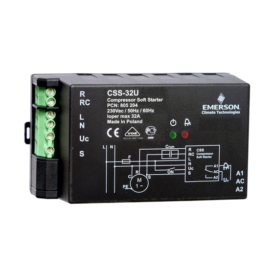
G e n e r a l i n f o r m a t i o n :
Compressor Soft Starters of the CSS-Series are used to limit the start current of 1-
phase compressors. For additional start torque a built-in start capacitor is switched in
parallel to the run capacitor. After start it is switched off. Supply voltage is
continuously monitored. In case of under voltage the compressor is switched off.
Restarts are delayed and indicated by a blinking greed LED. In case of alarm a signal
is indicated by the red LED. The alarm relay will be activated.
Soft starters are released for use with many compressors. (See list Fig.3).
CSS-32U / CSS-32W for compressor motors with nominal current up to 32A
CSS-25U for compressor motors with nominal current up to 25A
S a f e t y i n s t r u c t i o n s :
•
Read operating instructions thoroughly. Failure to comply can result in device
failure, system damage or personal injury.
•
According to EN 13313 it is intended for use by persons having the
appropriate knowledge and skill.
•
Do not exceed the specified maximum ratings for pressure, temperature,
voltage and current.
•
Before installation or service disconnect all voltages from system and device.
•
Unauthorized opening of the CSS will void warranty.
•
Entire electrical connections have to comply with local regulations.
•
Do not operate system before all cable connections are completed.
Disposal: Electrical and electronic waste must NOT be disposed of with other
commercial waste. Instead, it is the user responsibility to pass it to a designated
collection point for the safe recycling of Waste Electrical and Electronic
Equipment (WEEE directive 2002/95/EC). For further information, contact
your local environmental recycling center.
S e t t i n g :
•
No setting required. The Soft Starters automatically limit the start current based on
the connected compressor size. Several consecutive starts are required to learn and
optimize the start current of the attached compressor.
M o u n t i n g – D i m e n s i o n s S e e F i g . 2 , 4 :
•
CSS Soft Starters are for mounting in electrical switch boards only. The mounting
clip allows convenient DIN rail fixing; for secure mounting on any other flat
surface, it has four drill holes (Ø4.5 mm). The mounting clip can be attached to the
housing base in two directions, see fig. 4.
•
Protect CSS from direct sun light and water.
W i r i n g ( F i g . 1 , 2 ) :
Warning:
•
Use automatic circuit breaker F with characteristic of circuit control C.
Releasing current 25A for CSS-25U, 32A for CSS-32U / CSS-32W.
•
Do not use an additional contactor. CSS could be damaged.
•
Do not connect "Crun" capacitor to the "Run" lead of the motor. Connect it
between RC and S terminals as per wiring diagram. An additional start
capacitor "Cstart" is built in the Soft Starter
• Perform wiring as printed on the housing. CSS Contacts:
R
Output motor run winding
RC Output run capacitor
L1 230V 50/60Hz power input
•
The terminals are for flexible cable cross section 0.25 ... 4 mm
CSS-32W R- RC and L contacts:
•
The screws must be tightened with
L E D I n d i c a t o r C o d e s
green
red
Alarm Rel.
ON
OFF
ON
blinking
OFF
ON
ON
ON
ON
ON
1 x blink
ON
ON
2 x blink
ON
ON
3 x blink
ON
ON
4 x blink
ON
ON
5 x blink
ON
OFF
5 x blink
OFF
blinking
ON
OFF
OFF
ON
OFF
OFF
OFF
OFF
OFF
OFF
OFF
Emerson Climate Technologies GmbH
Am Borsigturm 31 I 13507 Berlin I Germany
Operating instruction
Compressor Soft Starter CSS-Series
S
Output start winding
Uc Start input ("on" if connected to 230V)
N
Neutral line
2
.
2
0.25 ... 6 mm
0.5... 0.6 Nm.
Message
System energized, normal operation
System energized, waiting for delay time elapsed
System test after power on
Motor current too low
System cannot start caused by low voltage condition
Start winding voltage too low after start sequence
Motor current too high (32 A eff)
Start capacitor error (damaged or disconnected)
Start capacitor or run capacitor error (defect relay)
Motor connection error
Internal error
System not energized or internal power supply defect
Main circuit breaker blown at power on
at transport can set bistable relays into wrong position. With this mode the relays will be reset to the correct position).
www.emersonclimate.eu
•
The wiring diagram per Fig.1 is an example how safety functions can be wired.
Crun Run capacitor
F1
Circuit breaker of control circuit
F2
Discharge gas thermostat
F3
High pressure switch
F4
Low pressure switch
O p e r a t i o n :
•
After all connections are wired, supply voltage can be switched on. Green + red
LED will be on for 30 sec after power up, then blinking green LED indicates the
initial delay time of 150 sec. Green LED on will indicate "ready for start".
•
Switch contact "Uc" to 230V (for min. 0.5 sec) starts the motor with limited start
current. The start sequence is monitored.
•
If the motor does not start, it is switched-off. A restart will be delayed for 5 Min.
A blinking green LED indicates the delay.
•
The compressor is switched-off, when "Uc" is disconnected from 230V. A restart
will be delayed. This is indicated by a blinking green LED. After elapsed delay
time the green LED will stop blinking; a restart is possible instantly.
•
For other messages see list of LED indicator codes below
T e c h n i c a l D a t a :
Operating voltage
Continuous compressor current, max.
Compressor start current limited to max.
"Uc" Signal
Impedance at "Uc" input
Alarm relay, AgNi (SPDT)
Resistive (AC1) max.
Operating temperature
Storage temperature
Start capacitor (Cstart)
Flexible cable cross section CSS-32W, (R, RC, L)
Flexible cable cross section (power lines)
Flexible cable cross section (alarm outp.)
Restart delay
Vibration resistance (10 ... 1000 Hz)
Protection acc. IEC 529
S t a n d a r d s
• Low voltage directive
• Contactors and motor-starters - AC semiconductor motor controllers and starters
• Safety for household (Part. No. 805204, 805205 only): EN60335-2-40
• Electromagnetic Compatibility:
• RoHS 2011/65/EU
2
• Marking:
P r o d u c t i n f o r m a t i o n p e r E N 6 0 9 4 7 - 4 - 2
Manufacturer:
Type codes:
Nom. operating current:
Operating voltage / Frequency: 230V nom / 50/60Hz
Operation category:
Device alternative:
Isolation voltage:
Surge voltage:
Protection acc. IEC 529
Pollution degree:
2
Remarks
Compressor might be ON or OFF
Blink frequency 0.5 Hz
Duration ~ 30 sec
Check wiring
Blink frequ. 2.5 Hz, 1.5 sec break between blink packages
Check wiring
Overload; locked rotor
Blink frequ. 2.5 Hz, 1.5 sec break between blink packages
Perform reset; exchange CSS if problem persists
check wiring of R, RC and S terminals
Severe problems, device to be replaced
If energized device to be replaced
Remove compressor lines R and RC; switch power on for few sec. Reconnect
compressor and power on again. (Note: Shock and vibrations
Date: 26.01.2016
F6
Circuit breaker of motor
K1
Contactor
Q1
Main switch
R2
Crankcase heater
230 V AC +10% / -15% / 50/60 Hz
CSS-25U:
CSS-32U / CSS-32W:
45 A / (30 A pcn 805209-805210)
230 V AC +10% / -15% / 50/60 Hz
>440 kOhm
250V~ / 3A
30V= / 3A
-20 ... +55°C
-20 ... +65°C
200 ... 240 uF
0.2 ... 6 mm
0.25 ... 4 mm
0.25 ... 2.5 mm
0,5 ... 5 Min.
4 g
IP 20
LVD 2006/95/EC
EN60947-4-2
EMC 2004/108/EC
Emerson Climate Technologies GmbH
CSS-25U CSS-32U CSS-32W
25A
32A max. / AC-53a; AC-58a
32A, Class 12, 60%
Hybrid motor starter with bypassed semiconductor
2.5 kV
1.5 kV
IP-20
CSS_OI_ML_R08_865724.docx
25 A
32 A
2
2
2
Advertisement
Table of Contents

Related Manuals for Emerson CSS Series


Summary of Contents for Emerson CSS Series
- Page 1 P r o d u c t i n f o r m a t i o n p e r E N 6 0 9 4 7 - 4 - 2 L1 230V 50/60Hz power input Neutral line Manufacturer: Emerson Climate Technologies GmbH • The terminals are for flexible cable cross section 0.25 … 4 mm Type codes:...
- Page 2 P r o d u k t i n f o r m a t i o n g e m ä ß E N 6 0 9 4 7 - 4 - 2 : • Verdrahtung gemäß Gehäuseaufdruck. CSS Kontakte: Hersteller: Emerson Climate Technologies GmbH Ausgang Motor-Hauptwicklung Ausgang Startwicklung...
- Page 3 I n f o r m a t i o n p r o d u i t p e r E N 6 0 9 4 7 - 4 - 2 : • Réaliser le câblage comme indiqué sur le boitier. Contacts du CSS: Fabricant: Emerson Climate Technologies GmbH Vers phase compresseur Vers enroulement auxiliaire du moteur...
- Page 4 I n f o r m a t i o n i p r o d o t t o s e c o n d o E N 6 0 9 4 7 - 4 - 2 : Uscita avvolgimento di marcia Uscita avvolgimento di avviamento Costruttore: Emerson Climate Technologies GmbH Uscita condensatore di marcia Uc Ingresso di avviamento (attivo se collegato a Descrizione:...
- Page 5 электродвигателя. Подключите его между контактами RC и S как показано на Информация о продукте согласно EN 60947-4-2 электрической схеме. Дополнительный пусковой конденсатор “Cstart” встроен в Производитель: Устройство Плавного Пуска. Emerson Climate Technologies GmbH Кодовые названия: CSS-25U CSS-32U CSS-32W Выполните подключение согласно схеме на корпусе прибора. Контакты CSS: •...
- Page 6 ZP36KSE-PFJ ZPD61KCE-PFZ Heating R410A ZR34K3E-PFJ ZH15K4E-PFJ ZH12K1P-PFZ ZP42KSE-PFJ ZP23K3E-PFJ ZHI11K1P-PFZ ZR40K3E-PFJ ZH19K4E-PFJ ZHI05K1P-PFZ ZP54KSE-PFZ ZP26K3E-PFJ ZH12K1P-PFZ ZR48K3E-PFJ ZH21K4E-PFJ ZHI06K1P-PFZ ZP32K3E-PFJ ZR61KCE-PFZ ZHI08K1P-PFZ ZP41K3E-PFJ ZHI11K1P-PFZ Emerson Climate Technologies GmbH www.emersonclimate.eu Am Borsigturm 31 I 13507 Berlin I Germany Date: 26.01.2016 CSS_OI_ML_R08_865724.docx...
Need help?
Do you have a question about the CSS Series and is the answer not in the manual?
Questions and answers