
Subscribe to Our Youtube Channel
Related Manuals for CSI Signature Series


Summary of Contents for CSI Signature Series
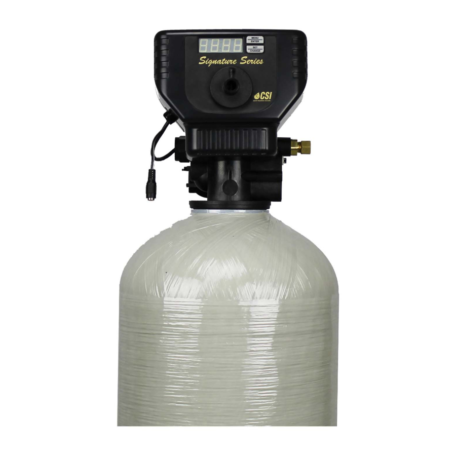
- Page 1 Signature Series Service Manual Your new Signature Series Valve is capable of high flow rates with simple to use electronics.
-
Page 2: Control Start-Up Procedures
Signature Series Control Start-Up Procedures Main Menu Menu/Enter Button 12:00 Set/Change Button 1. To Enter Main Menu Press the Menu/Enter Button (Time of Day will Flash) 2. To Set Time of Day Press the Set/Change Button (First Digit will begin to Flash) -
Page 3: Normal Operation
Signature Series Control Start-Up Procedures Normal Operation 1. (Metered Version) -Normal Display Alternates Between Time of Day and Gallons of Treated Water Remaining. -When the display is Showing Gallons Remaining and there is Water Flow the Upper and Lower Colon Lights will Alternate. - Page 4 Signature Series Control Start-Up Procedures Star ting Extr ener tion Cy Star ting Extr ener tion Cy 1. Starting Delayed Extra Cycle -(Metered Version) -If Gallons Remaining is not Already at 0 Press and Hold the Set/Change Button -After 3 Seconds the Gallons Remaining Display will Read 0 Example [ 0000 ]...
- Page 5 Signature Series Control Start-Up Procedures Sample R ener tion Cy le Displa Sample R ener tion Cy le Displa Step 2: Less Than 59 Minutes Step 1: Less Than 9 Minutes Remaining in the Brine/Rinse Step Remaining in the Backwash Step (For Filters &...
-
Page 6: Final Setup
Signature Series Control Start-Up Procedures Final Set-Up Final Set-Up With Proper Valve Operation Verified: 1. Add water to the top of the air check. Manually step the valve to the Brine Draw Position and allow the valve to draw water from the brine tank until it stops. -
Page 7: Master Programming Mode
Signature Series Master Programming Mode Entering Master Programming Mode -To Enter Master Programming Mode Press and Hold both buttons for 5 seconds. Note: All Master Programming functions have been preset at the factory. Unless a change is desired it is NOT neccessary to enter the Master Programming Mode. - Page 8 Signature Series Master Programming Mode 4. Regeneration Cycle Step Programming (1)(2)(3)(4) Press the Menu/Enter Button. The next 4 displays viewed are part of a series of option settings used to program the Regeneration Cycle. Up to 4 steps can be programmed.
-
Page 9: Master Programming Mode Flow Chart
Signature Series Master Programming Mode Flow Chart -To Enter Master Programming Mode Press and Hold both buttons for 5 seconds. To Change Value Regen. Type To Accept Value To Change Value Metered Regen. Day Version Override Only To Accept Value To Change Value Regen. -
Page 10: Water Conditioner Flow Diagrams
Signature Series Water Conditioner Flow Diagrams 1.) SERVICE POSITION Hard water enters unit at valve inlet and flows around the piston down thru the mineral in the mineral tank. Conditioned water enters center tube thru the bottom distributor then flows up thru the center tube and to the outlet of the valve. - Page 11 Signature Series Water Conditioner Flow Diagrams (Cont’d) 3.) BRINE/SLOW RINSE POSITION Slow Rinse. Hard water enters unit at the valve inlet - Brine. Hard water enters unit at the valve inlet - flows flows into injector housing and thru nozzle and throat...
-
Page 12: Valve Powerhead Assembly
Signature Series Valve Powerhead Assembly Page 12... - Page 13 Signature Series Valve Powerhead Assembly Parts List Ref. No. Quantity Part No. Description 0 ....1 ....20001X100 ......Powerhead Assembly Complete (Timeclock Softener) 0 ....1 ..... 20002X100 ......Powerhead Assembly Complete (Filter) 0 ....1 ..... 20003X100 ......Powerhead Assembly Complete (Metered Softener w / meter) 0 ....
-
Page 14: Control Valve Assembly
Signature Series Control Valve Assembly Page 14... - Page 15 Signature Series Control Valve Assembly Parts List Ref. No. Quantity Part No. Description 0 ....1 ..... 20001X200 ......Valve Body Complete 1 ....1 ..... 20001X201 ......Valve Body Only 2 ....1 ..... N/S ........End Spacer 3 ....4 ..... N/S ........Spacer 4 ....
- Page 16 Signature Series Control Valve Assembly (Filter) Page 16...
- Page 17 Signature Series Control Valve Assembly (Filter) Parts List Ref. No. Quantity Part No. Description 0 ....1 ..... 20001X200 ......Valve Body Complete 1 ....1 ..... 20001X201 ......Valve Body Only 2 ....1 ..... N/S ........End Spacer 3 ....
- Page 18 Signature Series 3/4” Turbine Meter Assmebly Ref. No. Quantity Part No. Description 1A ....1 ....20564X200 ....Meter Assembly, Turbine Complete Page 18...
-
Page 19: By-Pass Valve Assembly, Plastic
Signature Series By-Pass Valve Assembly, Plastic Parts List Ref. No. Quantity Part No. Description 1 ....1 ....20561X292 ......Plastic Bypass Valve Assembly 2 ....1 ....20561X290 ......fl” Yoke - Stainless Steel ....1 ....20561X291 ......1” Yoke - Stainless Steel 3 .... -
Page 20: By-Pass Valve Assembly, Brass
Signature Series By-Pass Valve Assembly, Brass Parts List Ref. No. Quantity Part No. Description 1 ....1 ....20561X270 ......Bypass Valve fl” Stainless Steel ....1 ....20561X283 ......Bypass Valve 1” Stainless Steel Page 20... -
Page 21: Dimensional Drawing
Signature Series Dimensional Drawing Page 21... -
Page 22: Valve Wiring Diagram
Signature Series Valve Wiring Diagram Page 22... - Page 23 Signature Series Service Instructions A. To REPLACE BRINE VALVE, INJECTORS, AND SCREEN 1. Turn off water supply to conditioner: 6. Insert screws thru injector cap and into mating a. If the conditioner installation has a “three holes in the valve body. Tighten screws.
- Page 24 Signature Series Service Instructions (Cont’d.) E. TO REPLACE METER TO REPLACE PISTON ASSEMBLY (Cont’d.) 1. Follow Steps A.1 through A.3. 6. Inspect the inside of the valve to make sure that 2. Remove two screws and clips at by-pass valve or all spacers and seals are in place, and that there yoke.
-
Page 25: Troubleshooting Guide
Signature Series Troubleshooting Guide SYMPTOM CORRECTION PROBABLE CAUSE 1. Softener fails to regenerate A. Power supply plugged into intermittent A. Connect to constant power source. automatically. or dead power source. B. Disconnected meter cable. B. Reconnect cable. C. Improper control valve programming. - Page 26 Signature Series Troubleshooting Guide (Cont’d.) SYMPTOM PROBABLE CAUSE CORRECTION 6. Loss of water pressure. A. Scaling/Fouling of inlet pipe. A. Clean or replace pipeline. Pretreat to prevent. B. Fouled resin. B. Clean resin. Pretreat to prevent. C. Improper backwash. C. Too many resin fines and/or sediment.
- Page 27 Signature Series Flow Data, Injector Draw & Slow Rinse Rates Page 27...
- Page 28 710 Orange Street · Ashland, OH 44805 Phone: 419-281-6829 Fax: 419-289-2375 www.csih2o.com SigMan 0308...
Need help?
Do you have a question about the Signature Series and is the answer not in the manual?
Questions and answers
I have a signature 3 and my meter has counted down since about mid November. How do I fix? Master programming seems correct
To fix a countdown issue on a CSI Series Signature 3 meter, check and reset the control valve programming. Also, inspect for a plugged or restricted drain line and clean it if necessary. Ensure the injector is not plugged and clean or replace it if needed.
This answer is automatically generated